I wish C3D had a rotary capability. I would love to engrave on round objects. I made this pen today and would like to engrave a name on it.
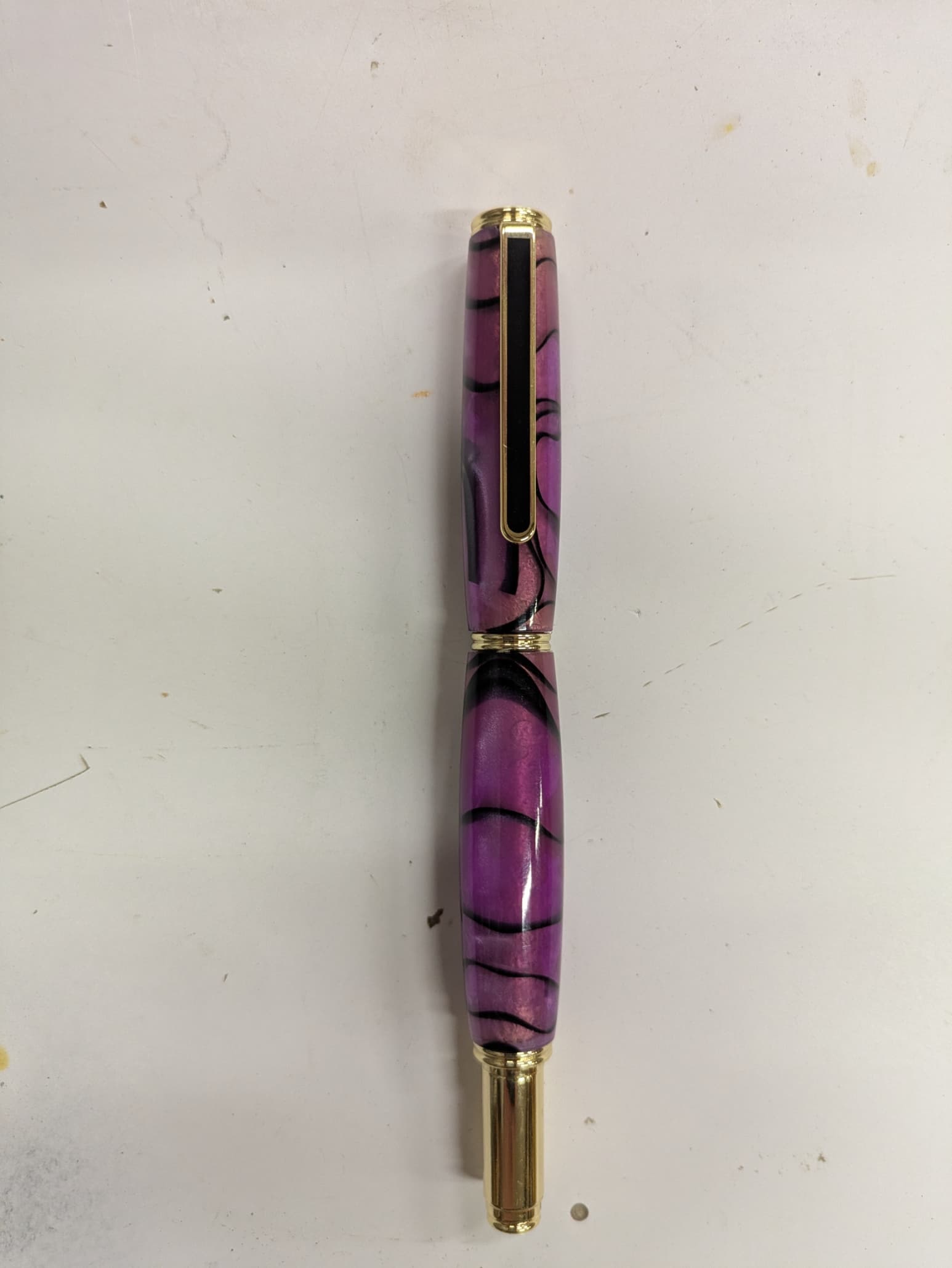
Is this just wishful thinking or will it ever happen?
I wish C3D had a rotary capability. I would love to engrave on round objects. I made this pen today and would like to engrave a name on it.
Is this just wishful thinking or will it ever happen?
I certainly hope it does, I have plenty of ideas if/when?. In the mean time I may just have to settle with a laser engraver with rotary attachment until they do. I’d rather spend my $$ on my S5 Pro however.
Rotary / 4th axis support would be pretty cool.
I’ve seen a few examples of guys that have retro-fitted 3 axis machines with 2 + rotary, usually using the Y axis to control the rotary, so XZC type machining. Of course it requires a CAM software that can create the toolpaths, or some manual editing of the toolpath.
I suppose for a specific configuration you could create a post that converts XYZ to XZC ??
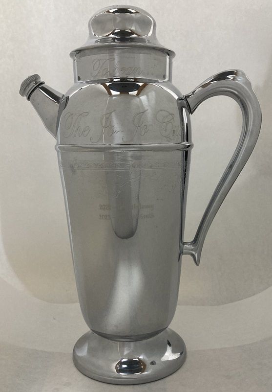
That being said, for something like putting names on pens you could do this on your machine in 3 axis. I engraved this trophy on my HDM. I used NX to do the programming, and to wrap the text around a model I created that matches the trophy. I’ve been told Vectric can ‘wrap’ toolpaths onto contoured surfaces.
Given your familiarity with nx and gcode in general, I’ll take whatever you manage to do and knock it down a few pegs for my own expectations ![]()
That said, if folks want to put together a quick change rotary axis project I’d certainly put time and money towards a reasonable, reproducible approach ![]()
I’m sure we could come up with a reasonable cost, reasonably accurate, and easy to swap in/out axis for wood working.
Plenty of other providers have ~plug and play solutions that we could work from ![]()
IMO it’s the g-code part that’s most likely to trip folks up ![]()
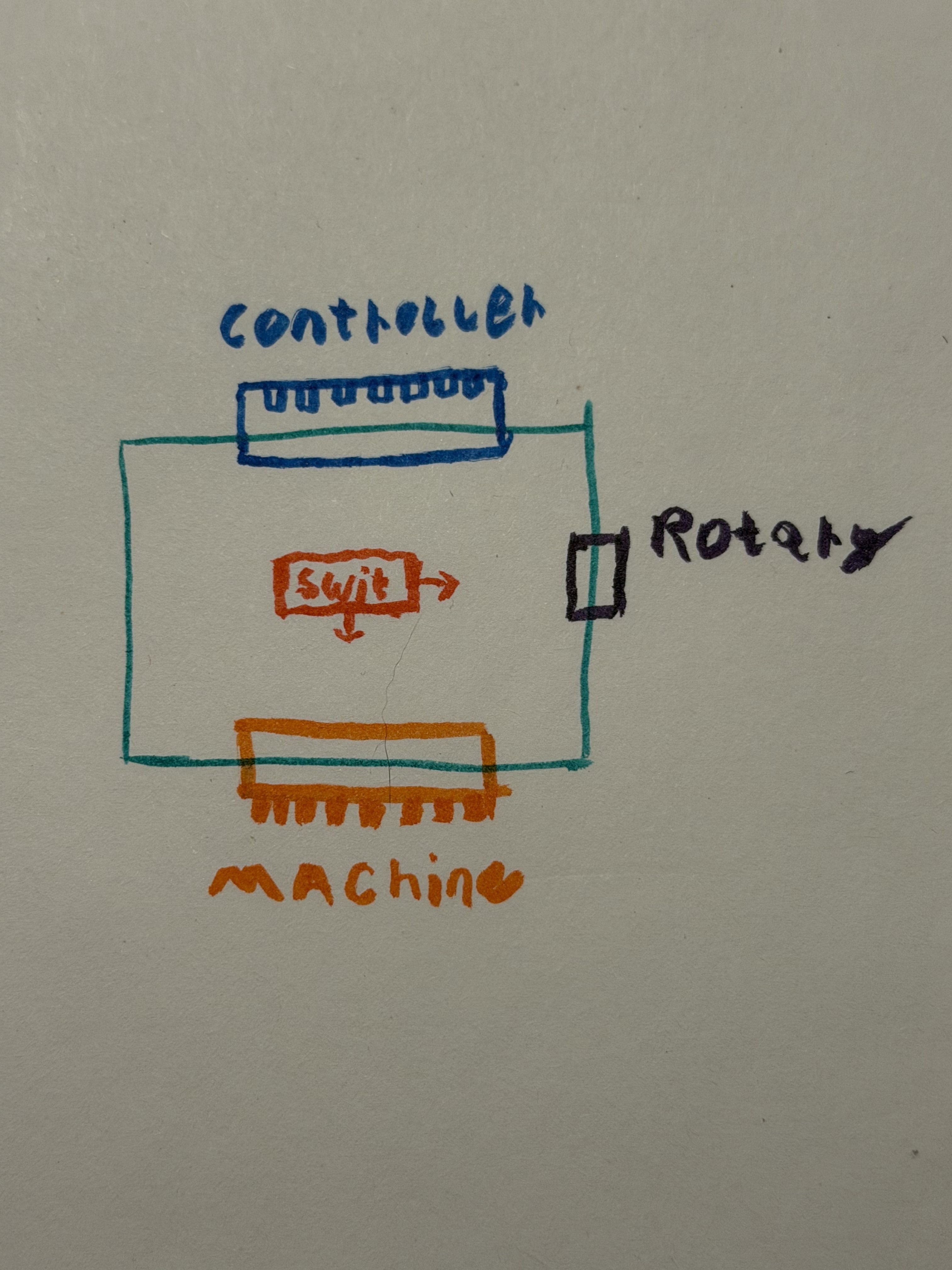
Thinking about this more, maybe the best way to get a conversion going is with a small pcb to sit between the machine and controller ![]()
The pcb could allow switching signal and power of the relevant motor axis being converted.
Something like this very crude drawing:
This would be nice because there’s no real modification necessary. Just a drop in addition. (Not sure about how homing and such would work though…maybe have to do the same switching mechanism for the sensor loom?)
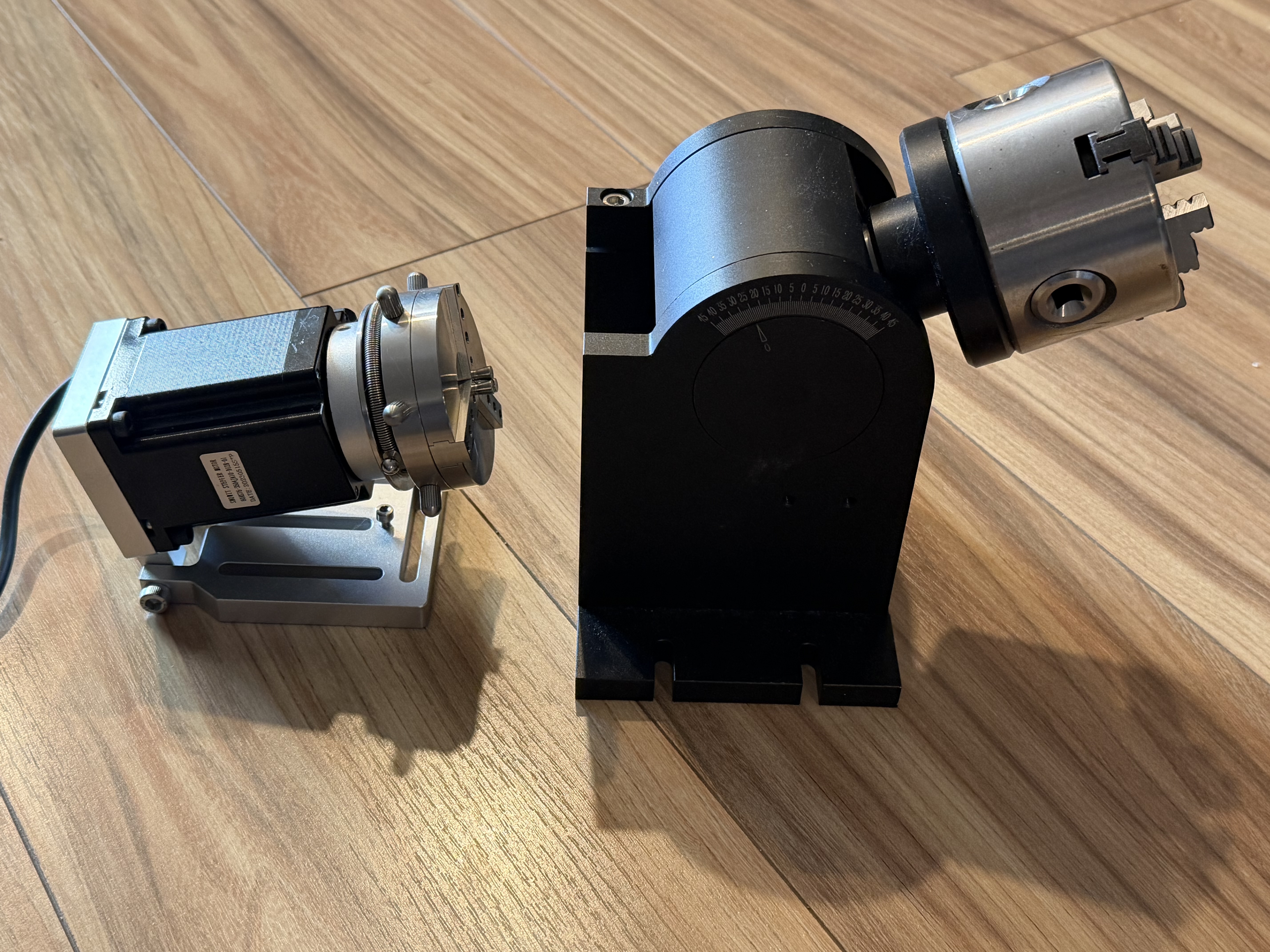
I’ve got rotaries from my laser and all of the necessary equipment on hand to make one if folks think it would work ![]()
What do folks think? Worth pursuing as an open source project? Put up the relatively simple pcb and settle on two reasonably priced/accessible rotaries that we know would work. (Small and large)
I’ve done a similar thing with adding a rotary my nomad so I expect it should be ~the same process. The benefit here being that woodworking probably doesn’t need near the same precision or rigidity.
If anyone has experience with an off the shelf rotary with built in homing, that might be interesting.
Let’s make something cool ![]()
When you switch between a linear & rotary axis, you will also have to change some parameters.
step/mm would become steps/degree, or similar.
Acceleration/deceleration & rotary feedrate would also be a concern.
This could be handled in the g-code, so perhaps a separate post for linear vs rotary?
It can certainly be done, and it has. Just not as simple as throwing a switch. ![]()
First and foremost, “I have no experience with this process”. Wouldn’t the rotary step motor act upon the “Y” G-code for command?
I think I would keep the y engaged and convert the x but that’s just preference on setup.
The cam should take care of that during post…I think. I’m not terribly experienced with this myself but I’m willing to figure it out and share findings ![]()
I guess it would depend on the rotary orientation for/aft vs left/right.
Yes, for a rotary table you could use XZC (C using Y), or YZC (C using X)
For a side rotary like a typical lathe, converted to mill coordinate system, you would use XZA (A using the Y value). But you could also use XYA, with the tool cutting at the back or front of the workpiece using the side of the cutter rather than the tooltip.
I set up a small Dremel lathe on the bed & used a stationary tool to cut a pen blank, essentially makeing it a cnc lathe, with no rotary in the gcode. I just used X & Z with Y fixed on the centerline of the lathe.
Their top end software version can. It’s pretty straight forward.
Most lasers support it. I’d like to see it on the Shapeoko because bed posts, legs, etc.
Vcarve Pro and maybe desktop can map 2D vectors to 3D surfaces. You don’t need to go all the way to Aspire for that.