as requested on support…
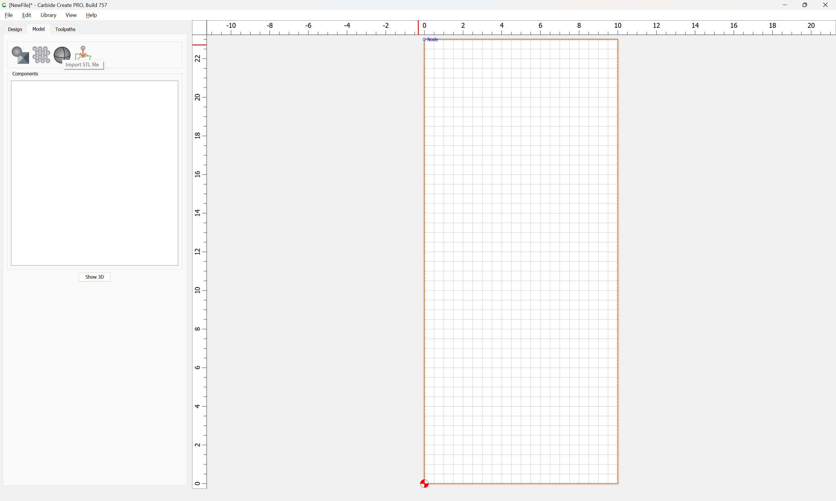
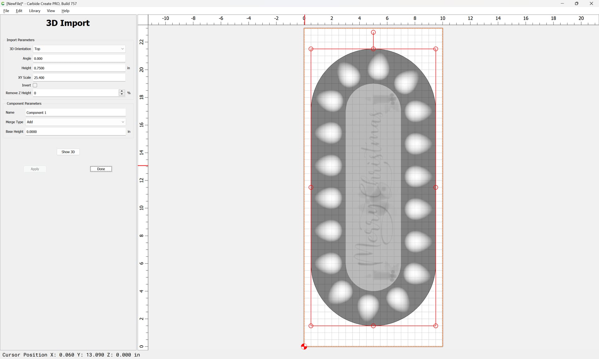
Given a 3D STL file:
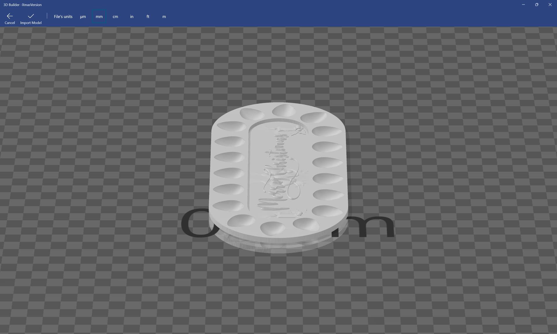
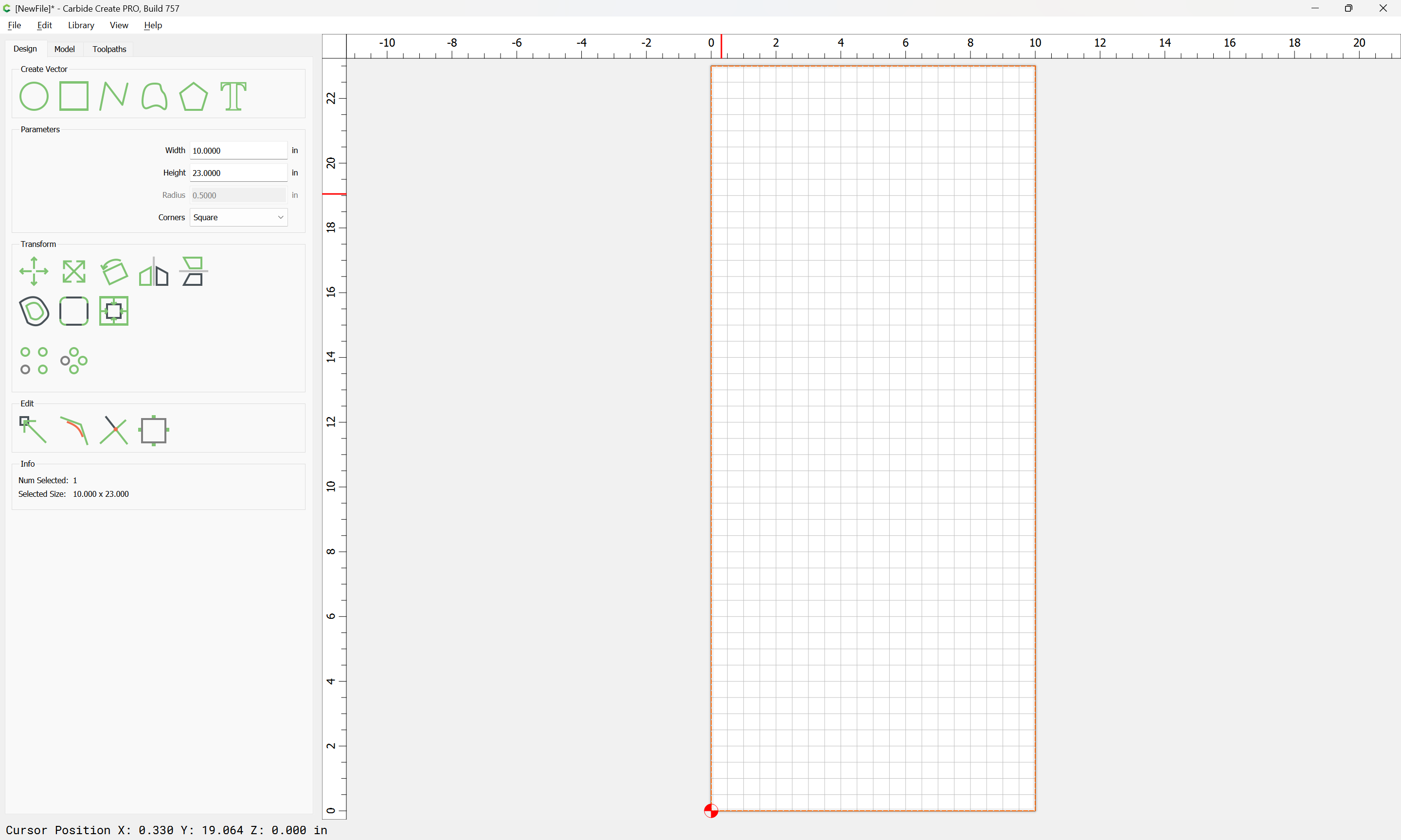
We check the dimensions (after repairing the STL if need be):
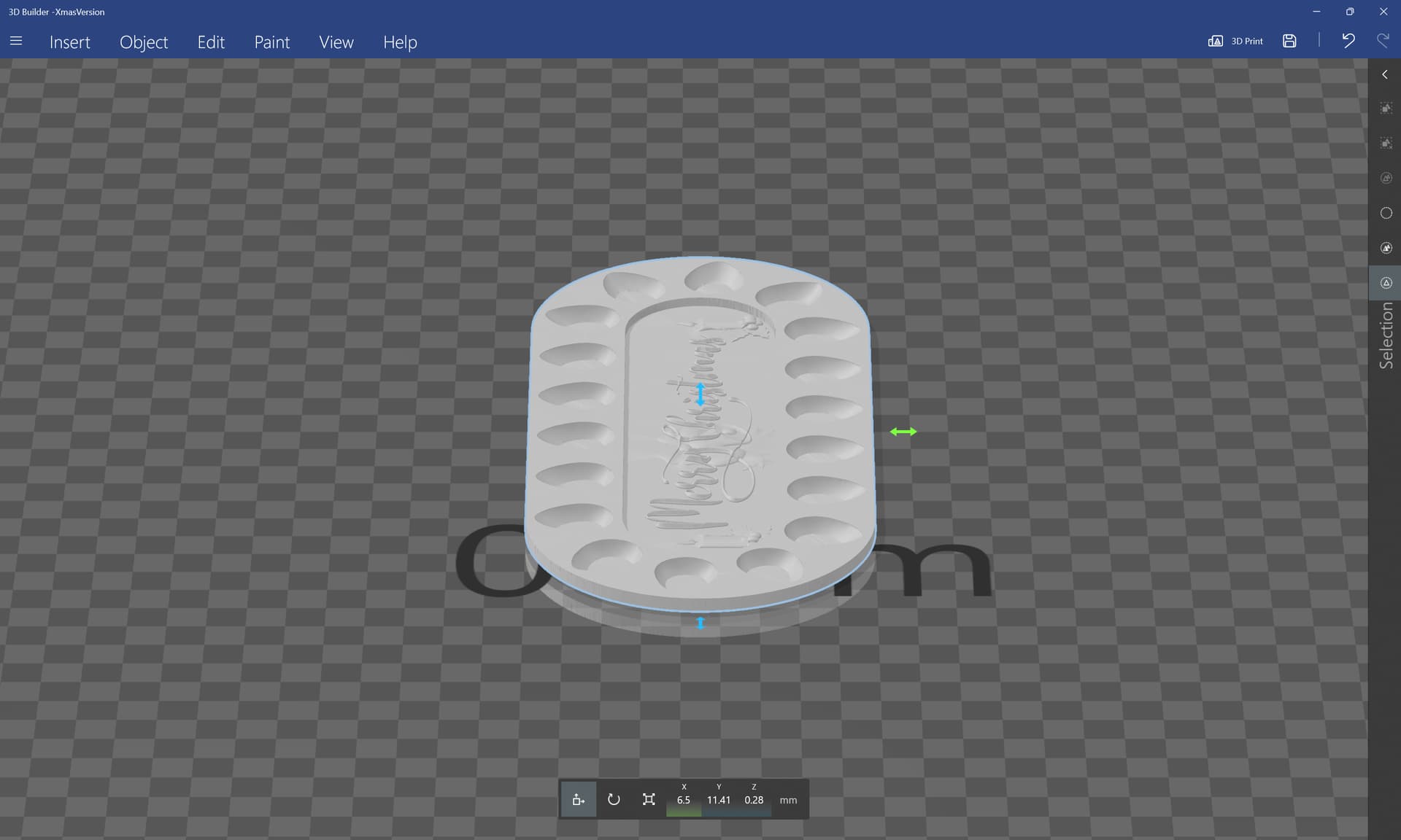
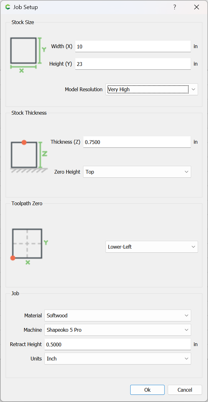
and seeing that they seem really small, just take a reasonable guess on dimensions and set up the job to match.
as requested on support…
Given a 3D STL file:
We check the dimensions (after repairing the STL if need be):
and seeing that they seem really small, just take a reasonable guess on dimensions and set up the job to match.
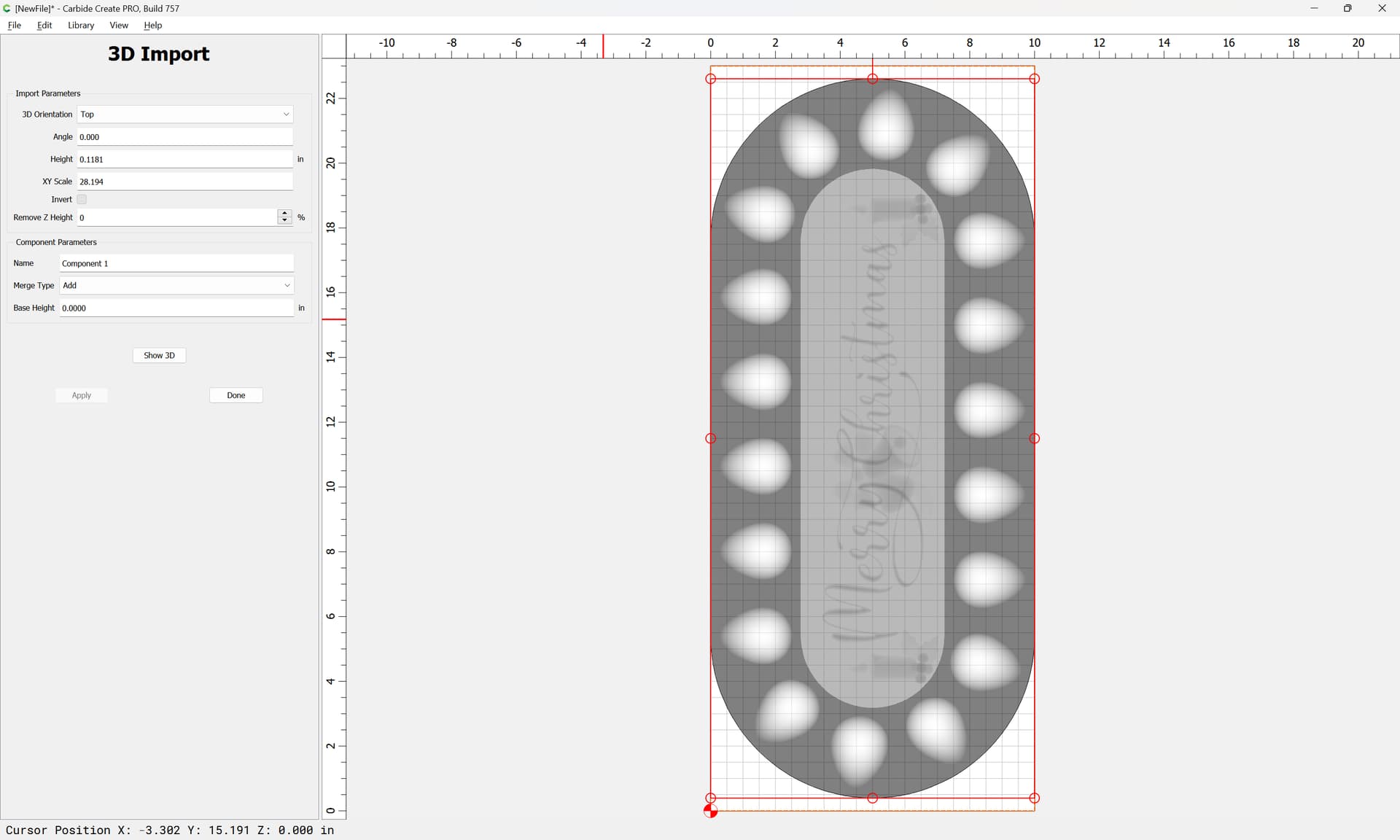
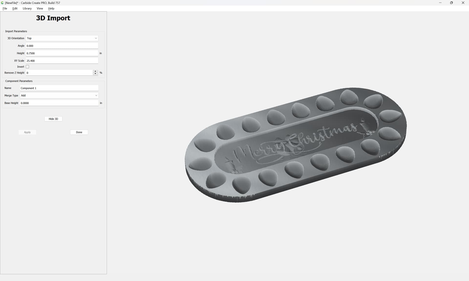
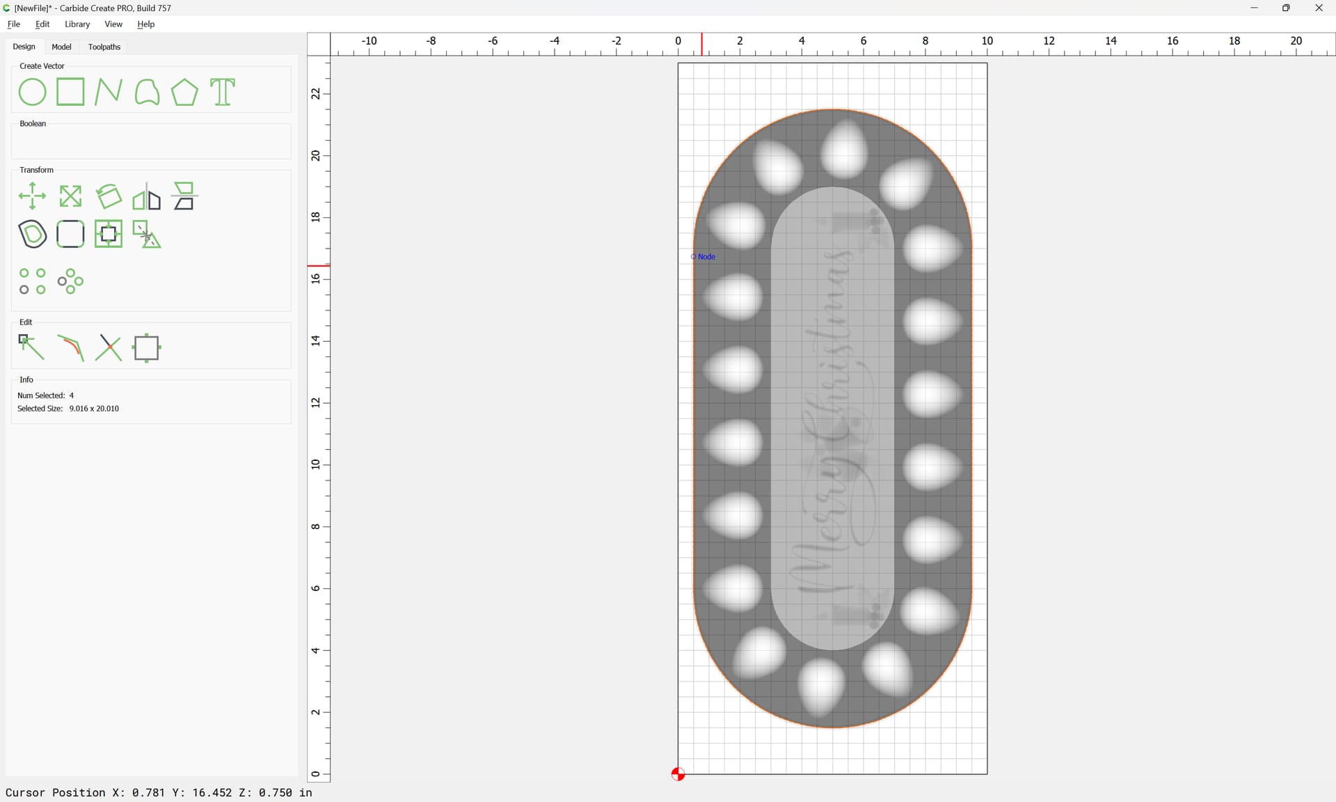
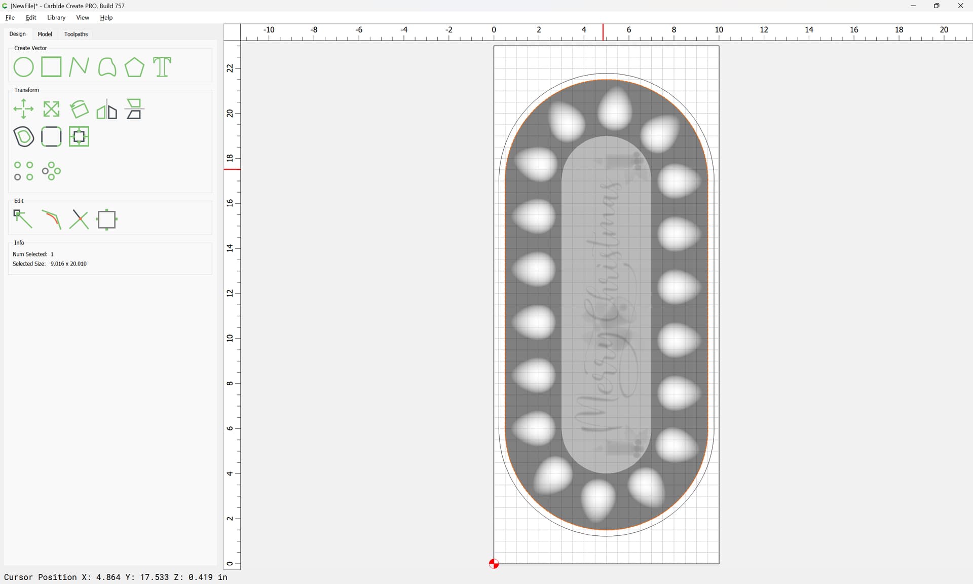
When an STL is imported, the pixel image is automatically traced:
which may be used as the basis for cutting around the design:
(if need be, ungroup and deselect the main geometry, then delete any excess elements)
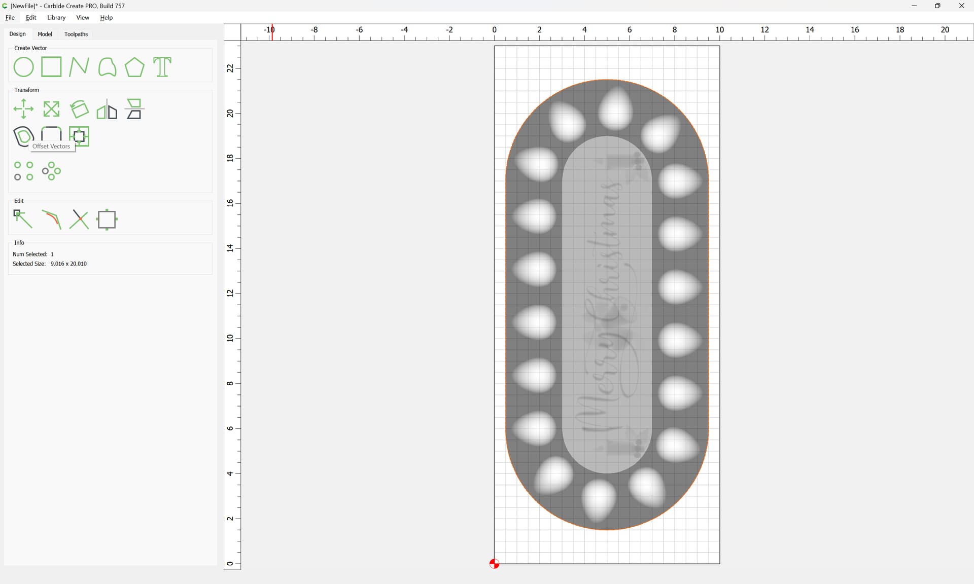
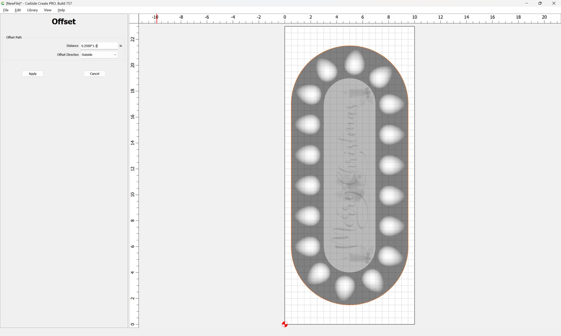
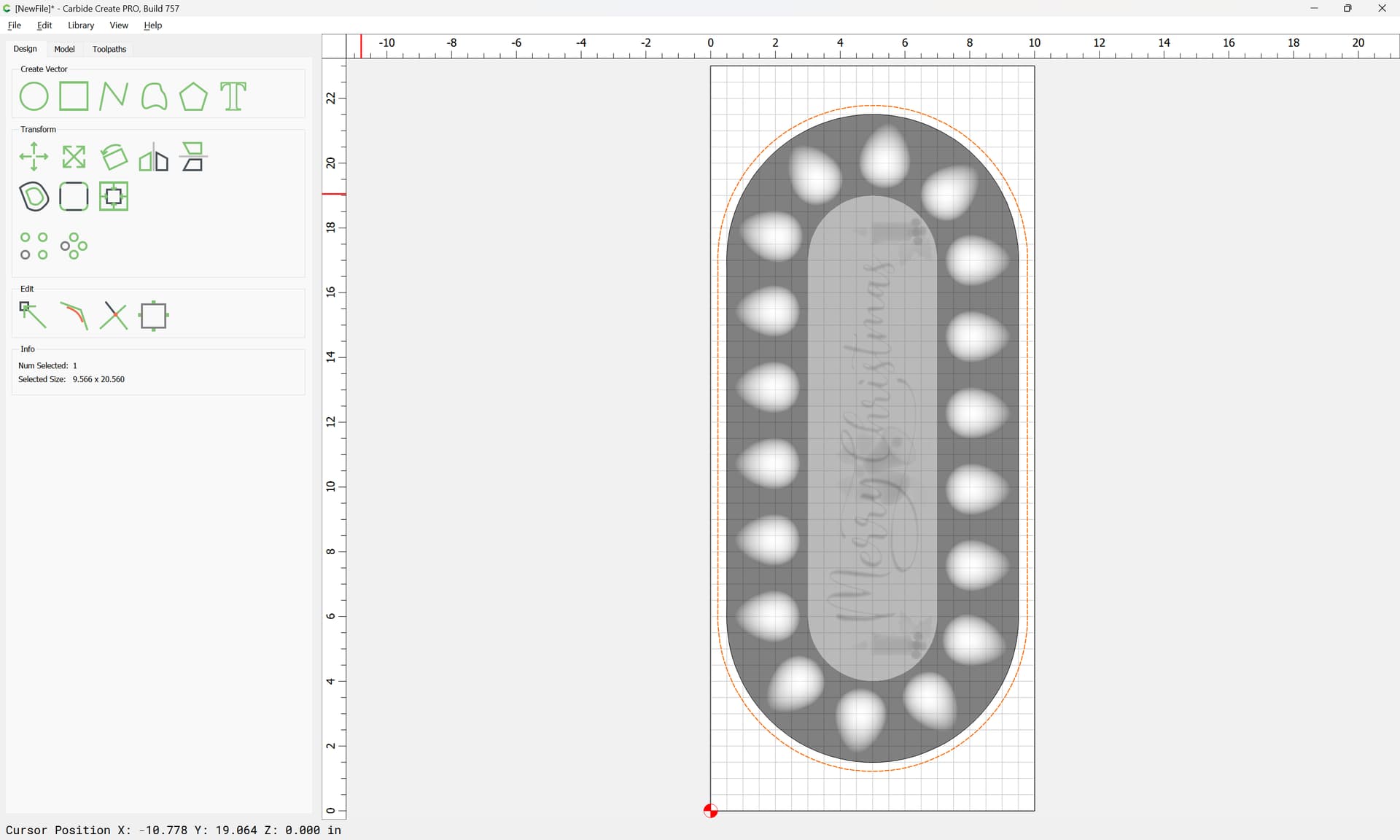
Offsetting to the outside by endmill diameter plus 10%:
will get us geometry which will allow cutting completely around the design for 3D toolpaths:
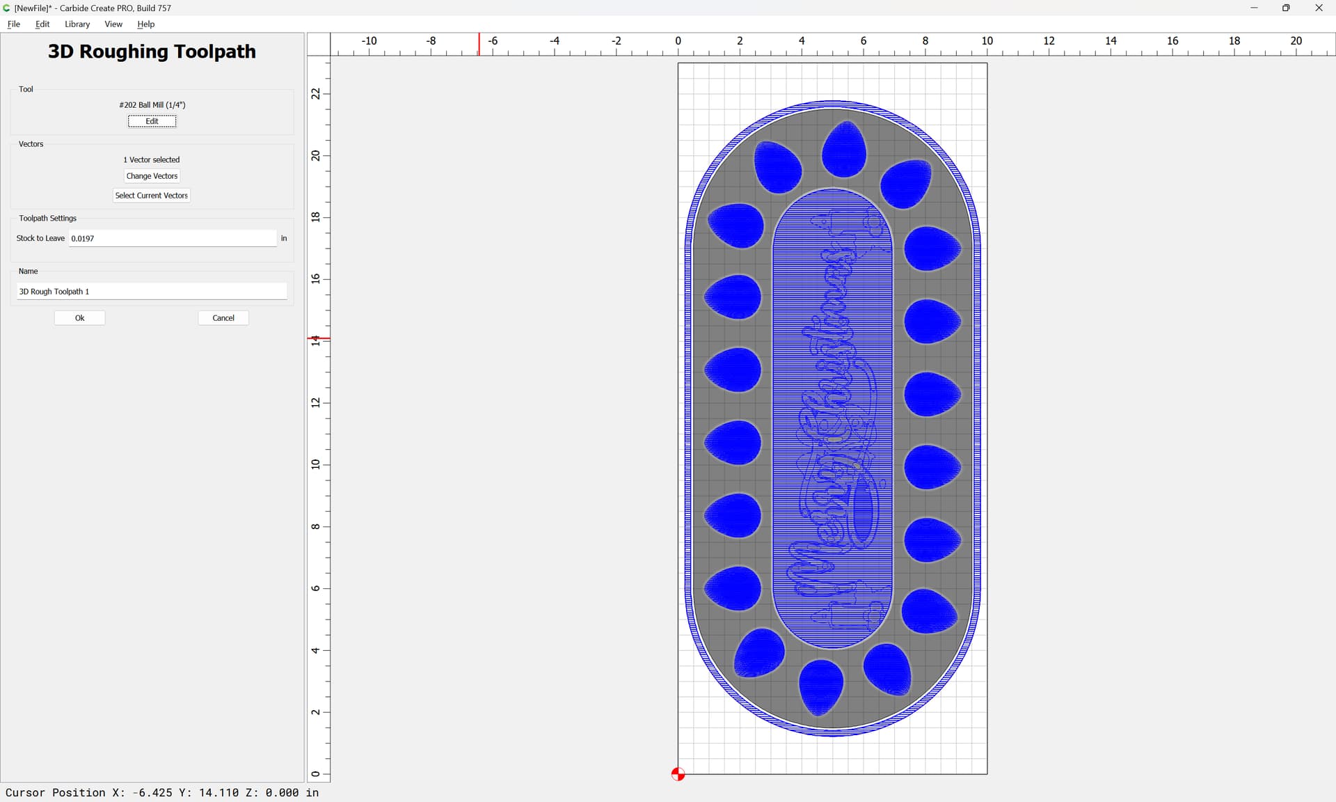
First a 3D roughing:
Normally one uses ball-nosed tooling for 3D work
Check the preview:
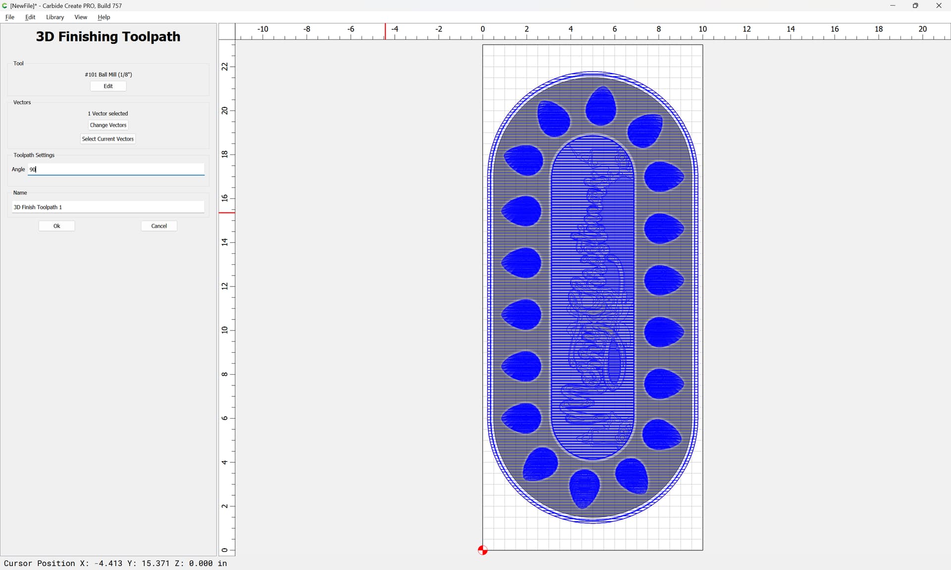
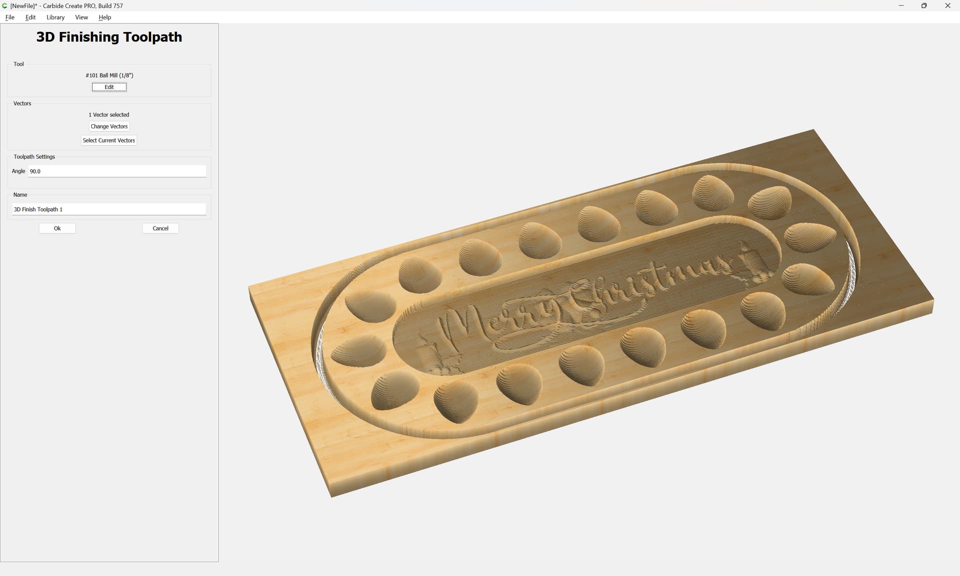
and then continue w/ 3D finishing toolpath(s) — if desired, step down one size (in this case from a 1/4" to a 1/8" ball-nose):
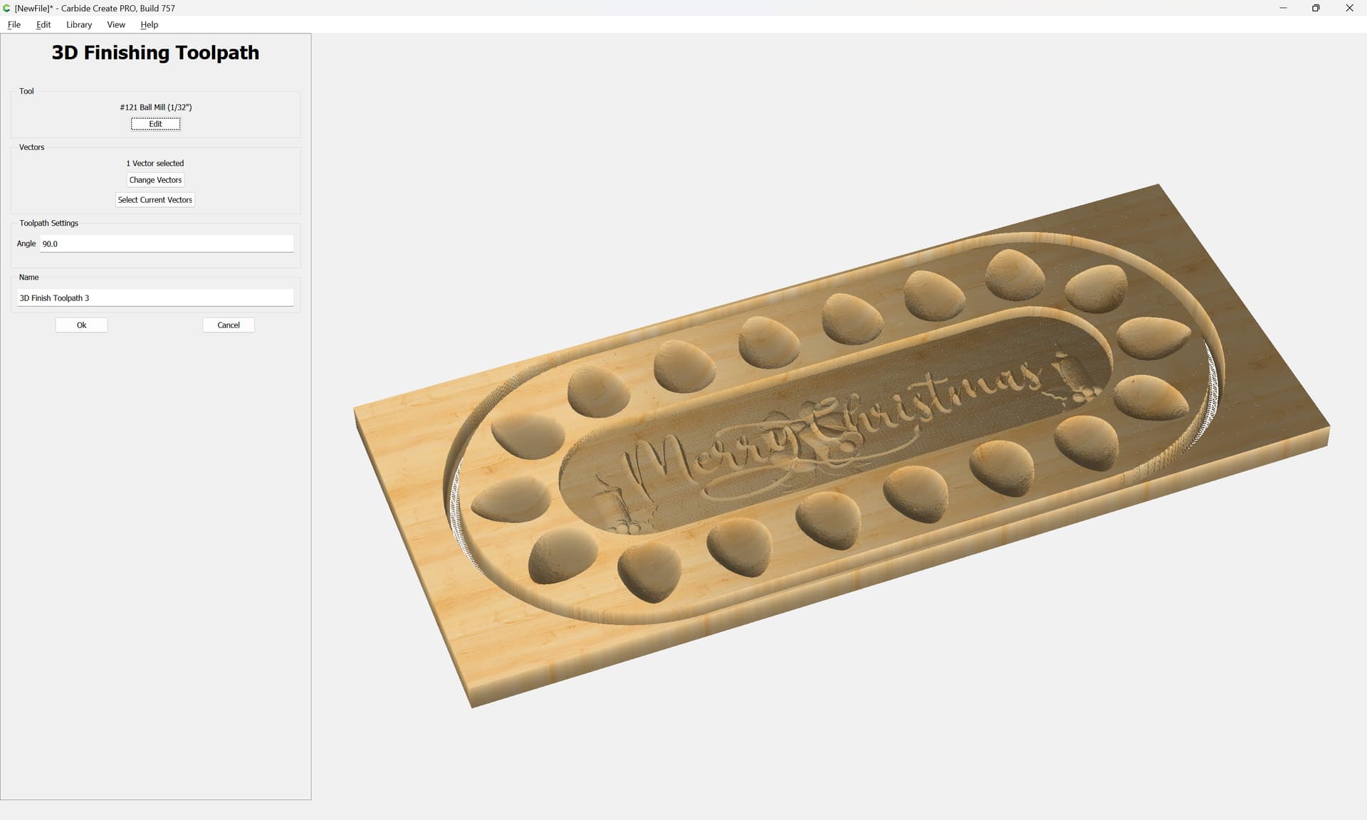
If desired, a finishing toolpath may be repeated, either w/ an even smaller tool (if appropriate) or with a smaller step-over — in this case we will use a smaller tool, but will change the selection, since the geometry around the edge is vertical and the shank of the tool would interfere:
Select the original geometry (this will keep the 3D finishing toolpath from trying to cut down along the edge and running the shank into the part):
One will want to balance the tool size and stepover against the duration of the operation, but if one is willing to have the machine work for a long while, quite fine results are possible (the final finishing toolpath should be with the grain of the wood):
This topic was automatically closed after 30 days. New replies are no longer allowed.