I’ve created some plans for my Nomad and, when I looked at the generated G-Code, it appears it first moves Z to -0.197 (inches). The next movement is to move the spindle to the first X and Y coordinates, after which it finally moves the Z axis to the safe retract height. I’ve attached a snippet of the startup of the job below. I used Camotics to simulate the job and it shows a long carve from the lower-left corner to the first position to start cutting. After that, all other rapid moves retract to 0.5000 (safe retract height) before moving the X and Y.
Am I missing something?
Michael
(STOCK/BLOCK,8.000, 8.000, 0.500,0.000, 0.000, 0.500)
G90
G20
(Move to safe Z to avoid workholding)
G53G0Z-0.197
(Pocket.Toolpath.1.-.Pocket)
M05
(TOOL/MILL,0.094, 0.000, 0.500, 0.00)
M6T10
M03S24000
(PREPOSITION FOR RAPID PLUNGE)
G0X1.7393Y7.2393
Z0.5000
G53G0Z-0.197 sets machine coordinate system and moves Z to -0.197 inches
M05 stops the spindle
M6T10 does a tool change
M03S24000 starts the spindle at 24,000 RPM
G0X1.7393Y7.2393 moves the spindle to those two coordinates (Z is still at -0.197)
8: Z0.500 finally moves Z to the safe retract height.
I don’t see a Z0 in this snippet.
I don’t see a Z0 either it the snippet you posted stops at the safe retract height. I wouldn’t expect a Z0 if I understand CC,.I would expect Z-DOC as the next Z change.
Yes, that was what I was trying to do in my comments, but didn’t make it as clear as you did. However, just before the first rapid move of X and Y (G0X1.7393Y7.2393), Z is at -0.197 which means the bit will be dragged through the material from the lower left corner to X=1.7393, Y=7.2393, cutting right through some of the project.
Michael
No, the Z is just below the endstop on the Z. if you want to verify.this and are comfortable editing the gcode file, just delete everything after the move.that you think is going to be a problem. Then, you can see what this gcode will do by setting Z like you want to (sounds like stop top), remove the stock, running the gcode and then putting the stack back in place.to see it cleared it the whole way through the operation.
I believe it is necessary to configure CAMotics so that it is aware of the machine working area in order for G53 to work correctly, but that’s just a guess about how a 3rd party program works.
Please contact their tech support to work this out w/ them.
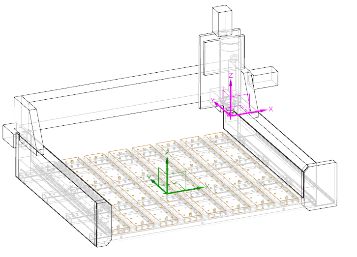
When you initialize your machine, it sets the G53 home zero point at the back/right/upper limits of the axes. This is “MACHINE” zero. (Magenta)
Then you load a tool & set the “WORKPIECE” zero (Green). (Which is actually G54, but that is the implied default, so it doesn’t appear in your program).
So when it says G53G0Z-0.197 it means go to the point 0.197 below the MACHINE Z 0.
So this line should go all the way to the top, but stop 0.197 before the limit.
G53 on these machines is not modal, so any line without it will measure from the WORKPIECE zero.
Your next movement line G0X1.7393Y7.2393 uses G54. so it could also be G54G0X1.7393Y7.2393 and it would still work the same.
@Tod1d - Thanks. that really helps. Did you make that visualization or is from someplace along with other visualizations. I’d like to double-check what I do “know” about G-code.
Michael
Keep in mind that many machines & controllers implement these codes a bit differently, Carbide Motion included. For example, CM always uses G54 for it’s “Fixture Offset”, (G53 references machine coordinates). M30 not only ends the program, but sends the machine back to the home position.
M03 either prompts you to turn on the spindle, or turns on the spindle using the VFD, and dwells for a couple seconds to let the spindle come up to full speed. M06 moves the machine to the tool change position, prompts you to load the tool, and if you have bitsetter turned on, moves to it & measures the tool.
I actually have a fairly good understanding of G-code, but was missing that piece. I was wondering what other pieces I’m missing. I’ll re-reference the spec you referenced again and see if I can fill in the blanks.