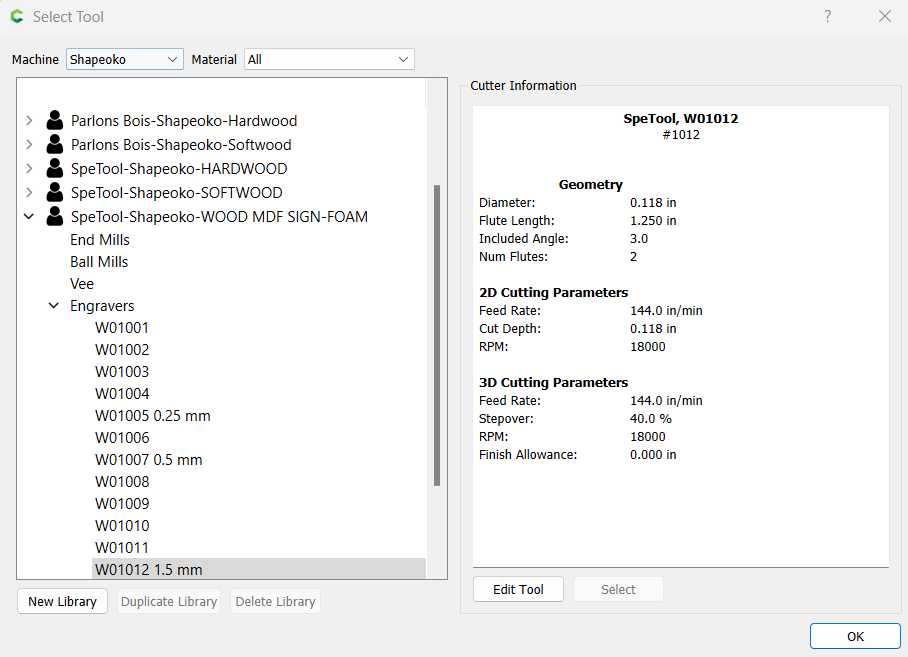
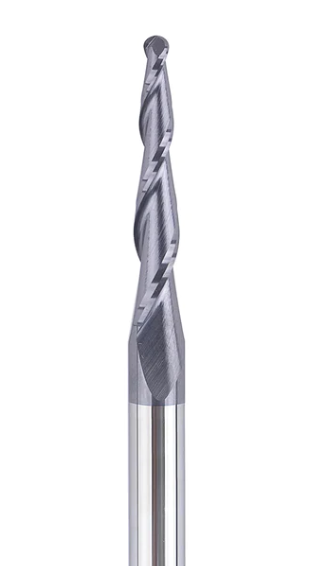
I have a SpeTool CA W01012 CNC 2D and 3D Carving 3.02 Deg Tapered Angle Ball Nose 1.5mm Radius x 1/4" Shank x 1-1/4" Cutting Length x 3" Long 2 Flute SC TiAlN Coated Upcut Router Bit.
I created an inlay job. The result is not what the simulation show. It is removing more wood than it is suppose to do. Here is the config in CC for the Tools.
Anybody know where the problem is? For now my only theory is that SPE is not providing the right information in CC.
How would you setup a tapered angle ball 3 degre bits in CC?
This kind of geometry isn’t really supported by CC. The only tapered bits it supports are V Bits, and CC assumes they come to a point when calculating depths.
If you use a TBN where CC expects to see a VBit, then everything will be over-cut, since a TBN at a given depth of cut is wider than a VBit at the same depth.
The only option for TBM is to make a custom tool and tell CC it is a ball end mill and not a TBM. CC does not understand TBM. using it as a ball mill be careful that the tapered part does not cut something above where it is cutting. Something like a topographical map where you have things higher up that could contact the side edge of the TBM. C3D has come a long way but not quite far enough. You have to admit that for free it is pretty robust. They have been steadily improving since I started with version 3. Version 7 is heads and shoulders above v3.
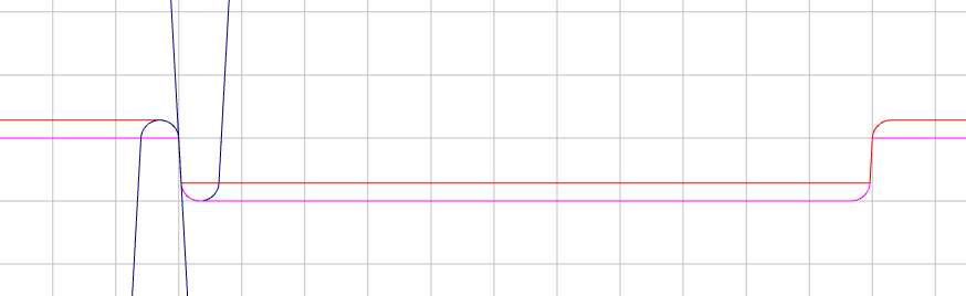
1st, your tool has an included angle of 6.04°
To program this in CC, you need to do some math & offsetting.
Advanced V-Carve only works with Vee tools, so enter your cutter as a 6° Vee
Round off all sharp corners on your design by the radius of the tool (1.5mm)
For the female, offset the design inward by the radius of the tool plus the taper (3°) at the depth you will cut. (For a 5mm pocket with that tool, the offset would be 1.685mm)
For the male, offset the design outward by the same amount.
I like to model a section view to visualize the math.