I know this has been covered many times but let me give it a go. This is how I understand the male creation of the inlay. The female portion is well understood and there seems to be no confusion there. The depth of the female VCarve really doesn’t matter but what ever we make it, we know the male inlay must fit down inside minus a little bit for glue as well as giving clearance between male and female when assembled.
After creating the female VCarve, we are told to mirror the drawing in the horizontal plane and save it as the male. Now we set our material on the Job Set Up page. Now looking back on our screen, we see an inverse image of the female. In my mind that image now resides at the bottom of the material. Like taking the lid off the peanut butter jar, we set the lid on the counter with the top facing down. (top is now bottom and bottom is now top) If the lid were see through, we would see an inverse image of the writing on the top of the lid. That’s the image I want to carve and it resides below what is now the top of my material.
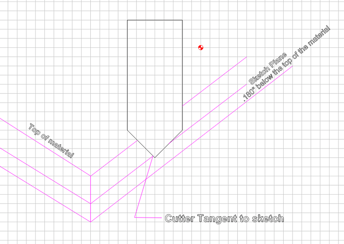
The key thing to remember from here on out is that the software will keep the cutter tangent to the sketch line no matter what depth values we input. Think of the cutter coming down vertical but then when it hits your sketch, it begins to slide sideways at the angle of the cutter, staying in contact at all times.
Let’s say the female carve was .200" deep.(the number everyone seems to like but does not matter) In my mind, the male sketch (the peanut jar lid) is now .200" below the top of my material. The thing is, I really don’t want the male to bottom out in the female so I lift the image up by .020" and now it resides at .180" below the top of my material. The Sketch Plane. This is my Start Depth. What this just did was create the .020" glue gap between the floor of the female and the bottom of the male insert. Now I need the cutter to slide down below the sketch to give clearance between female block and the male plug. This is where I tell the cutter to go to a Max Depth of .220" creating the .020" gap between the two. The thing to remember here is, your plug, insert, inlay, what ever you want to call it, resides above the sketch plane and is what is inserted into the female. Anything you cut past the sketch plane is clearance and part of the material you will mill off after you insert the male plug into the female Vcarve.

I know what your thinking now, what about the material that resides above the sketch plane? My tools can’t take that much material at one time. Let’s create some rough cuts. You may have to make several roughing cuts and that’s fine. The first Vcarve may have a Start Depth of zero with a Max Depth of .085". The next will Start at .085" with a Max Depth of .180" and the final will Start at .180" with a Max Depth of .220". This could potentially create a lot of tool changes. Depending on your skill and comfort level, there are ways around so many tool changes but require editing the G code and go beyond the scope of what I am trying to convey.
