Is there any possibility of adding air gap to inlay mode? And is it possible to add it manually? Thanks
Are you talking about what is being referred to here as the “Saw Gap”? (as opposed to the “Glue Gap”)
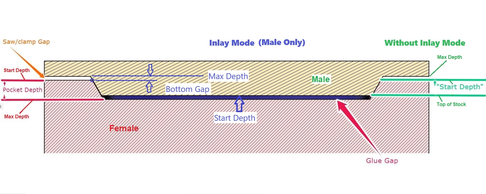
I believe you can control this by changing the max depth & glue gap on the male part.
For example, my female side uses Start Depth: 0.0 Max Depth: 0.5
And my male inlay uses Start Depth: 0.0 Max Depth 0.5 Bottom Gap 0.1
If I want the glue gap to remain 0.1, but the upper gap to be 0.2, I would change these values to
Start Depth: 0.0 Max Depth 0.6 Bottom Gap 0.2
1 Like
I was talking saw gap. I at first considered exactly what you propose however I think the inlay mode will just make the inlay exactly the size that would fit a deeper inlay. Certainly looking at simulations of doing that it won’t work with inlay mode (note this is exactly what I would do if not using inlay mode) I may try a test cut because of that could work it would be great
I’m pretty sure the Bottom Gap in the inlay mode represents the Saw Gap.
The glue gap would be the difference between the Female Max depth and the Male (Max Depth - Bottom Gap).
So in both of my examples above the male should insert into the female 0.400, with a 0.100 glue gap.
The “Bottom Depth” controls the plane at which the vector gets traced for the male part. Before the inlay mode this would be controlled by the male Start Depth, but then the first depth of cut would be the start depth plus the depth of cut on the tool. Now the DOC starts at the top of stock, but the vector is traced at the (Max Depth - Bottom Gap) level.
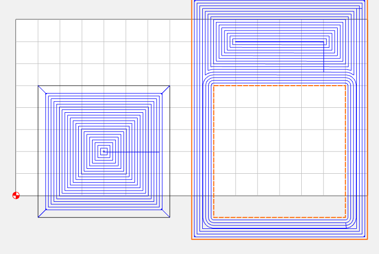
I did several tests like this to help myself get a grasp of it, where I let the inlay hang over the edge of the workpiece so I could put them together & see the gaps.
“Of course, that’s just my opinion. I could be wrong.” ![]()
2 Likes
This topic was automatically closed after 30 days. New replies are no longer allowed.