Inlay Not Perfect

I am trying to understand why my inlays are still having gaps in multiple places (some as big as 1/16th inch). The way this program was built was with all the designs and tool paths in one master file and then I would move them and disable/enable as I cut them (just so everyone is aware). The 2 tool paths that I am referring to are the ‘Male’ and ‘Female Inlay’. I am cutting 0.150" deep with a 60 degree on both and then using inlay mode at 0.020" depth on the male only. Would it be best to use different setting/depths? What typical dimensions does everyone use for inlays? My female is black walnut and my male is maple. All items were drum sanded before so they were very consistent. I have the 5 Pro if that is needed information.

ScottPate_Sharon’sKitchen.c2d (1.1 MB)

Hi Dave, I would suggest you orient the inlay and the pocket along the same machining axis. If any of the tolerance issues you are experiencing are due to a difference between X and Y axis mechanics having them rotated would amplify these issues.

2 Likes

To calibrate one axis to another see:

2 Likes

Thank you! Would that be an issue with the machine then or would it just be tolerance driven on the machine? Good note as I did NOT do that. Does the 0.150" seem too much? What about the inlay mode 0.020"?

0.150" seems way too large, 0.020" seems plausible but I’m on a belt driven 3XXL from 2019. I would start with validating the calibration following @WillAdams advice.

3 Likes

Will, I have the 5 pro so where would you typically see the issues if the x/y was off a bit (no belts to test stretch)? I will try on a larger scale as you detail out but want to make sure I look for the proper locations that could be the issue. Any noises I would hear if they were off a bit? I did check and tighten a couple bolts during and post assembly.

One of the items I have done to check and it actually relates to the program above is recut the engraving. I will explain. I cut the engraving portion (measurements) at a 0.025" depth and it was not enough depth. I let the program continue until it cut the board out with tabs. I then updated the program to cut from 0.025" to 0.050" on the engraving only, loaded it into motion, re-zeroed and let it eat. It was SPOT ON the entire time which is about a 6" by 8" area. I remember because I was stunned it was so close (and impressed). Maybe this doesn’t actually test the x and y as much as repeatability, but I thought it was a good note either way.

What depth would you recommend? 0.100"? I mean it will save me time not going so deep… haha

Please verify things mechanically first — if all that checks out, then we can check the file and underlying program logic.

1 Like

The depth of the inlay needs to be based on the purpose of the piece. If this is an active cutting surface and you want to be able resurface it a few times then a thicker inlay with a more acute V-bit. For a display piece you can get away with a thinner inlay and the 60 degree V if it can provide the detail you require. The glue gap should be OK. There are several recent posts about the new inlay feature that have good suggestions and work flow descriptions. Picture of the issues are always helpful.

1 Like

Will, I want to make sure I have the process down as I think I am fuzzy.

  1. Find square stock (larger seems to be better)
  2. Set zeros on the top left
  3. Cut the first rectangle down the Y Axis
    (This is where I may be fuzzy)
  4. Cut the second rectangle down the X Axis
  5. Validate that the cuts are square to the piece (This could be verified with a known square item correct or measurements from the edge of the cuts - 0.25" based on the file above (1 square))

looking at your file; a few comments:
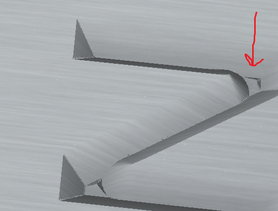
you don’t have a Area Pocket Tool selected for the “female” toolpath; which I think might be at least part of your problem. The font (at least on my machine) is wide enough that some of the V paths would go deeper than the 0.15"… and if you don’t select an area clearing tool, carbide create will cause those bits to not be cleared at all… not even by the V bit. This will result in a “bump up” being there that will get in the way of a good fit for the inlay, see picture of the simulation below:
Nshot


second comment; I see you have a depth per pass for the V bit of 0.1"… in my experience that is VERY aggressive for V cuts… and might lead to inaccuracies… for most V bits I tend to not go more than 0.04" as depth. (but this depends on the quality and geometry of your V bit as well as on the type of wood)

Might not be the end of the world, but if you want to cut this aggressive, I’d suggest doing a cleanup pass (as I describe in Creating inlays using the new Carbide Create feature)

as others mention it’s usually a good idea to cut the plug in the same direction; in part for accuracies… but also it’s usually better to have the wood grain in the same direction (so expansion/contraction of wood doesn’t fight itself later)

4 Likes

This is one of my favorite inlay tutorial videos.

Hey Will, I did the test and I believe there may be some issues with the X and Y. What steps can I take to make that right?

Per the machine operating checklist: Machine operating checklist , the basic points of adjustment for a machine are:

  • Pulley set screws — verify that these are in-place and secure — be sure to check all axes/pulleys (including Z on machines w/ belt-drive Z-axis, for an HDZ, check both coupler screws).
  • (for the SO3/4, X- and Y-axes) V wheels / eccentric nuts (per assembly instructions)
  • (for the Pro, and SO4 Z-axis) Lubrication of the linear rails: CNC Machine Maintenance c.f., https://web.archive.org/web/20211127125707/https://docs.carbide3d.com/assembly/linear-guide-maintenance/Linear_Rail_and_Guide_Maintenance_02-17-2021_v1.0.pdf
  • (for HDZs, and HDMs, and SO5 Pros) check that couplers between the motor and ball screw are secure, for the SO5 check that the DAC which transfers the rotary motion of the ball screw to linear machine motion is secure on the carriage/gantry
  • Belt tension (see the relevant step in your instruction manual, Note that the X-axis motor is held in place on standoffs and if those bolts are loose this can cause belt tension issues. Also, belt tension for the Y-axis stepper motors needs to be even/equivalent on each side — a significant difference can cause skipping on one side eventually resulting in lost steps on both. Measuring belt tension, squaring and calibration

Naturally, this assumes that all the wiring is in good condition and all connectors secure per the Machine Operating Checklist. Verify that all wiring is in good condition and all connectors are secure, and that all wiring leading into connectors are properly in place and are secured so that the wiring leading into and away from connectors will not shift.

A good video overview on setup:

Ensure that all screws are in place and secure, esp. on the linear rails on a Pro.

1 Like

Will,

Thanks again for the help. I was out more than desired (0.75" corner to corner) and moved the corner to corner difference to 1/16" (over about 76 inches to where I measured). Do you believe that will be okay (I assume it will be)? I redid your test and it was very square over 16 inch piece I used (much better than test #1). Also, lubrication was already done and I usually perform that often (but I did fill the carriages also). The ball screw items still have their lubrication in front of the carriages.

I will try another inlay when I can, but this shall help!

This topic was automatically closed 30 days after the last reply. New replies are no longer allowed.