In this tutorial I’ll be showing how to use the inlay feature in the latest Carbide Create (in beta at the time of writing). I’ll try to make this tutorial as detailed and entry level as possible (lots of pictures and small steps), if you’re a more advanced user this might be too boring for you.
Before you begin
Unlike most other types of cuts, you need to plan ahead a bit more for your inlay.
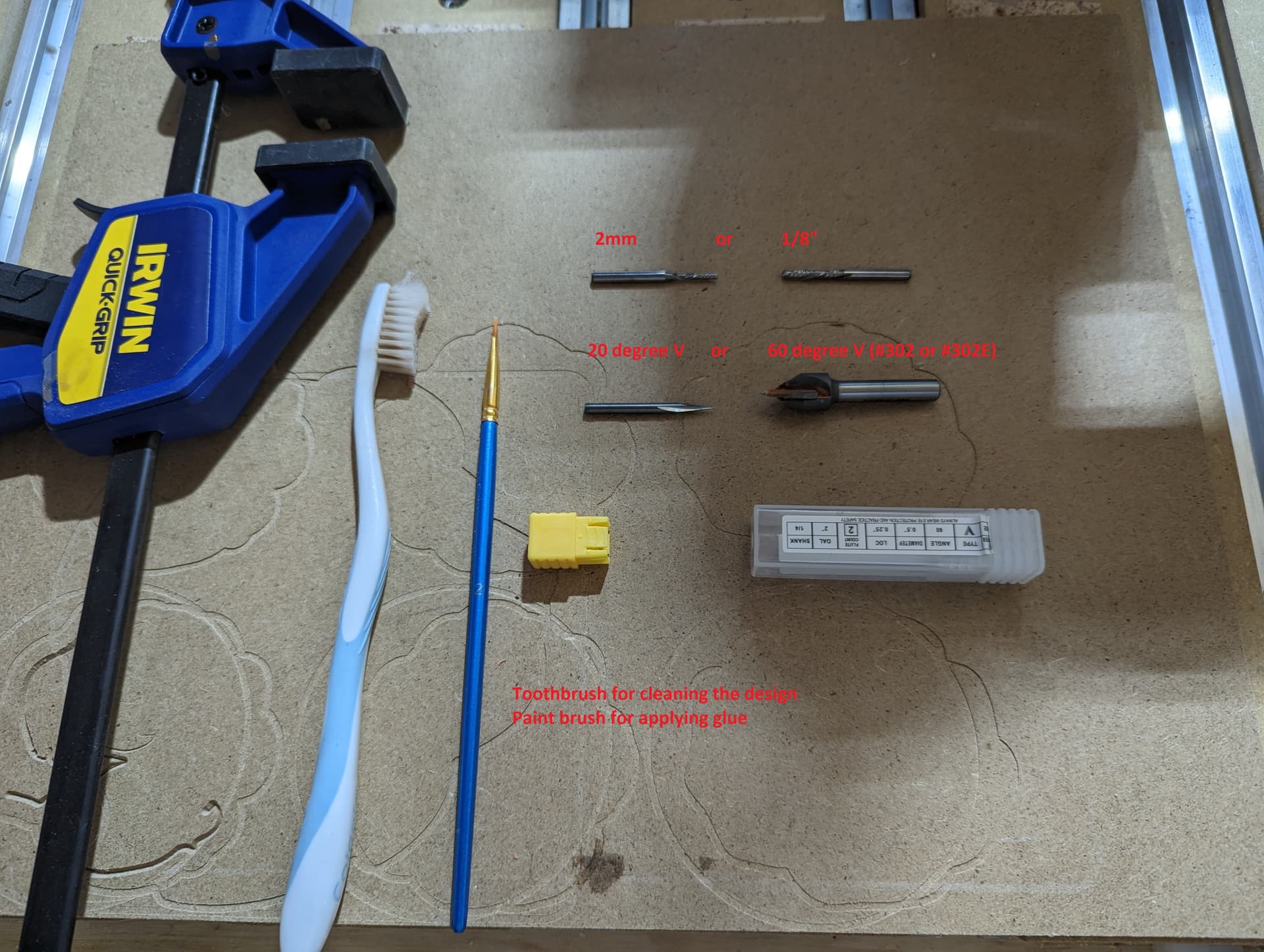
First, the tools you need; you need a V bit as well as a 1/8" or smaller regular endmill. A paintbrush for applying glue, a tooth brush to clean up any fuzzies in the cut and… of course a clamp or two for the glue up.
You’re going to be using 2 different types of wood, and obviously the more contrasting the colors are the better the effect. The types of wood matter a lot for this; I would stay away from more “stringy” woods such as Oak, since it will be harder to get sharp details in such woods with the V-bits we are going to use… to contrast with Walnut, which is able to hold fine details very well. For most designs this matters the most for the plug, and less so for the base. Walnut for the plug has the added bonus that you can get walnut-colored woodfiller, which is a good backup in case something does not go exactly perfect.
The thickness of the material for the plug is important, it needs to be a little thicker than the depth you want to use, but most certainly not by too much. I will be using a 0.25" thick piece of wood for the plug, and will use a 0.2" depth. My design will be approximately 12" x 3" in size; if you got a much bigger design I would recommend going thicker than 0.25"/0.2" just for general stability… but you would need to adjust both dimensions (say 0.5" material for a 0.45" deep cut)
The thickness of the base matters less as long as it as thick or thicker than the plug.
The V-bit is obviously important, and mostly, the pointier the bit (lower numeric angle value) the better. I would recommend against using 90 degree bits, and use at least 60 degrees. I have made inlays all the way down with a 20 degree V bit. If you have lots of fine details in the design, definitely go for something like 20 or 30 degrees. An important note on cheap “ebay” or “amazon” bits: Some of the cheaper “20” degree bits might be 19 or 21 degrees in reality, and accuracy in the angle matters for the result. Also important is that the point is actually a point, and not a bit flat; if it has a flat bit then your bitsetter will get the Z depth wrong which has the same impact as having the wrong angle.
There are ways to test the angle of your bit by doing cuts, and I might do another tutorial about this some time, but for now, if you’re not sure about the accuracy of your super fine bit, but you trust your 60 degree bit… you might want to just go for 60 degrees initially. I’ll be using a 20 degree bit for this tutorial.
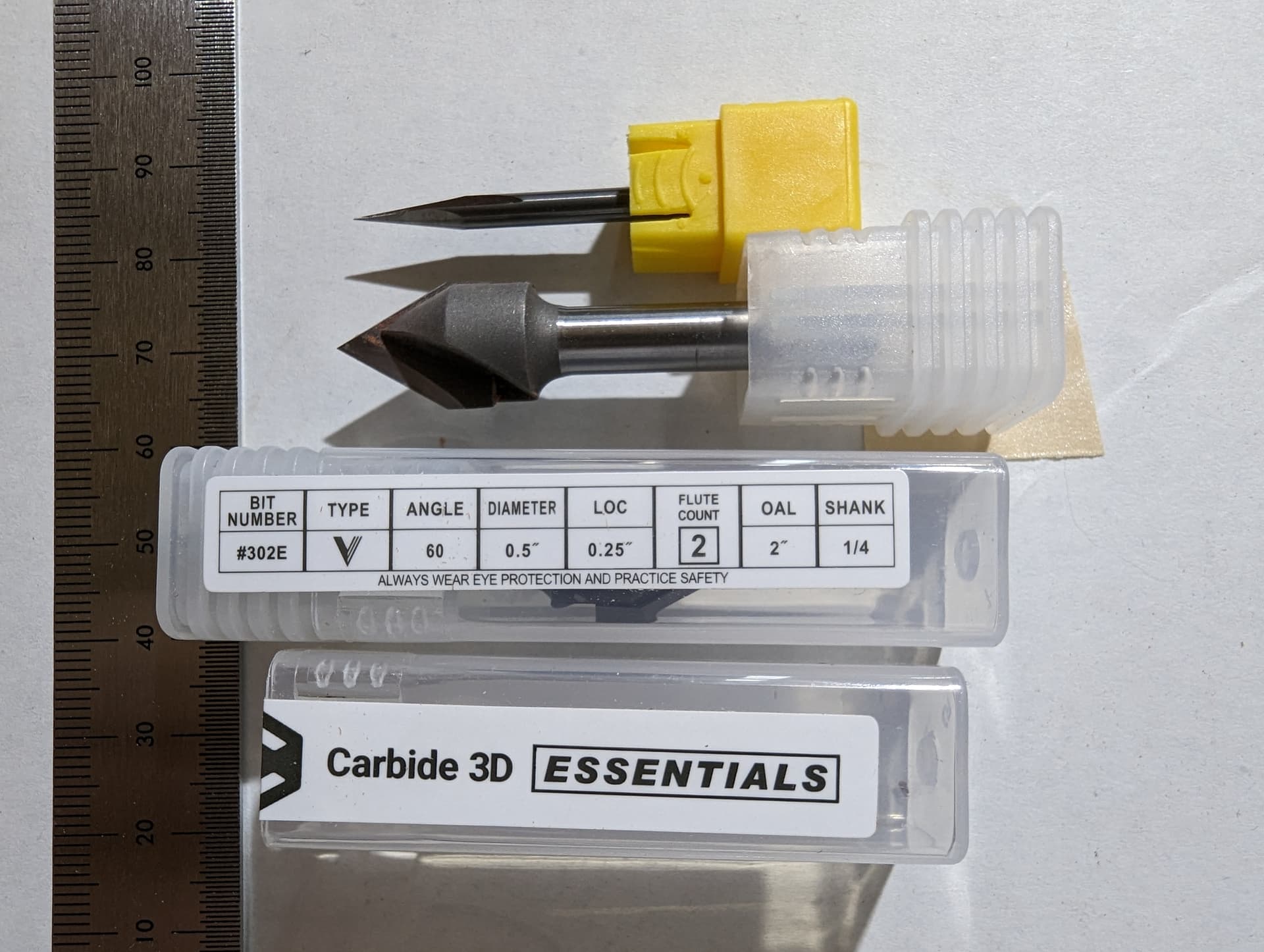
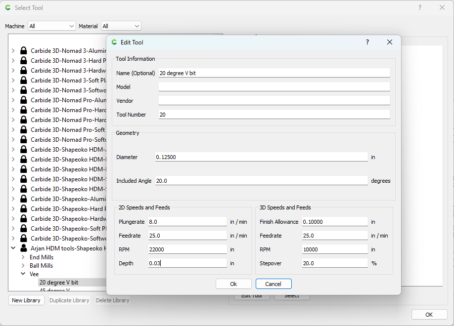
Some folks have asked for the settings for a 20 or 30 degree bit. Below is a screenshot of how I configured my 20 degree bit in Carbide Create. Note that the Feed-and-Speed settings are pretty conservative, but a 20 degree bit is petty thin compared to a 60 degree bit (see picture below to compare how sturdy Carbide3D’s bit 302E is, versus the flimsy 20 degree angle bit) and I decided based on “Lets not break the V bit, I only have one of these” rather than optimizing for job run time.
Note the biggest thing I tweaked was the maximum depth of cut, it’s pretty shallow so that the V bit takes only tiny bites out of the material. I’m sure some experts here on the forum can be convinced to share their wisdom on how to optimize if runtime is paramount for you.
There are some considerations for the design as well: I have found that larger contiguous “blobs” work really well, but that very small dots, or long thin lines are much more challenging to get good results with. We’re going to glue these into an opposing opening, and then remove the back material with some slightly heavy forces… if the detail is too tiny there might not be enough glue area to withstand those forces and tearout happens. There’s options to reduce forces later on but still, overall, larger blobs tend to work better in general…
Building the Base
There are obviously 2 parts to the design, the base and the plug. The plug is just a modification to the base… so we design the base first.
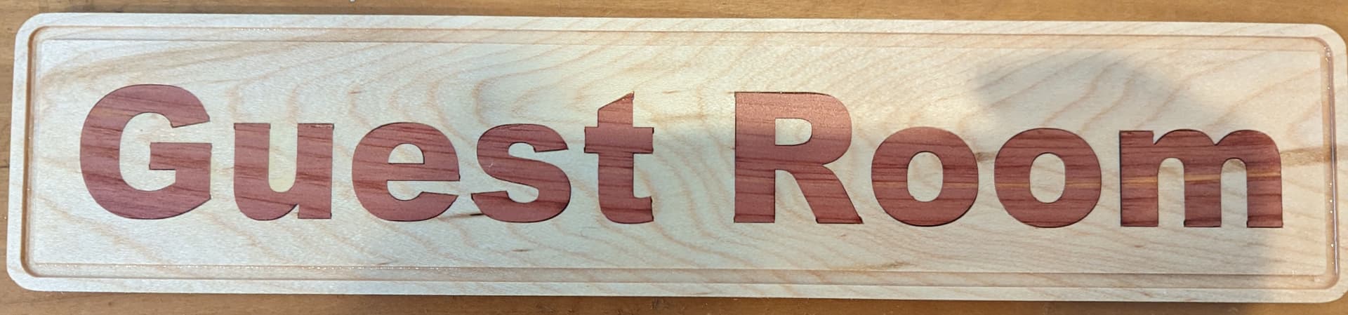
For this example, I’m going to make a “Guest room” sign; it’s complex enough to not be a toy, but simple enough to not get distracted by design elements in the tutorial.
(in the picture below I added a decorative groove that I won’t be adding in the tutorial)
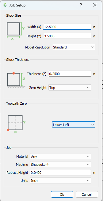
Step 1: The settings
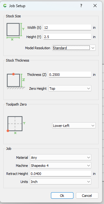
In the settings (sprocket menu) of the design, we set up the width, height and depth of the stock (12.5", 3.5" and 0.25") as well as the zero points (lower left, top of the material):
Step 2: The frame
By using the “rectangle” design button, we’re first adding a rounded frame around the sign like this:
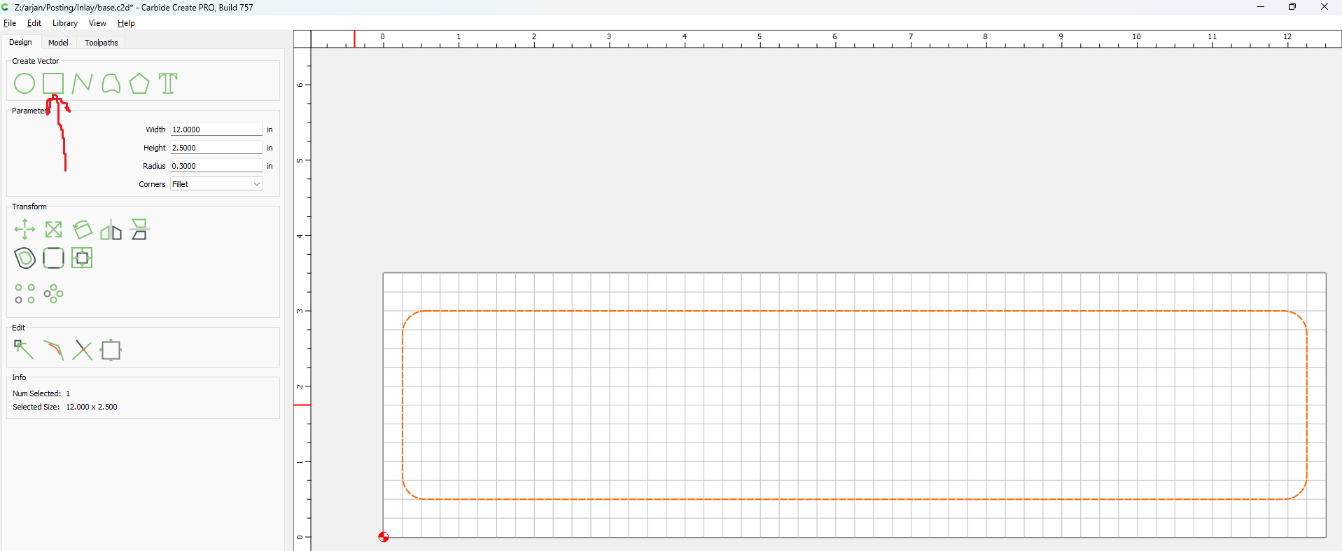
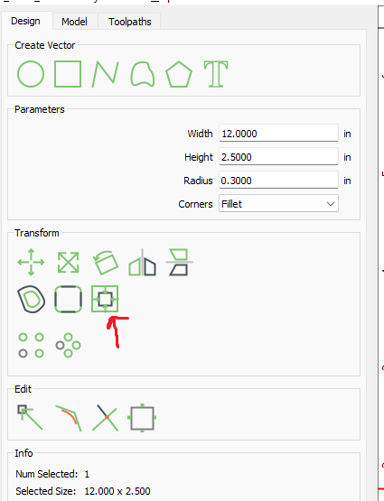
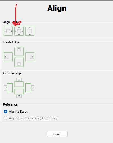
And then we align it to the middle of the stock using the align button:
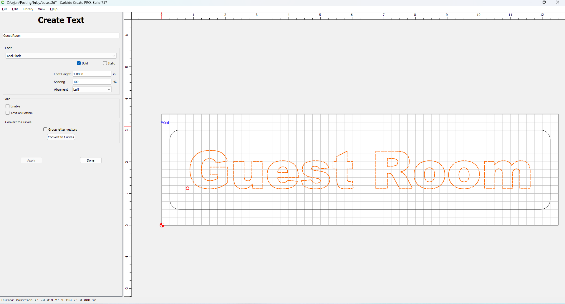
Step 3: The Text
Using the “text” button, we’re adding the words ‘Guest room’ to the design:
And using the exact same steps as in step 2, we center the text to the design
(since the frame is also centered, this makes the text be centered to the frame as well)
With this, the basic design is done.
Step 4: Toolpaths
We’re going to make 3 toolpaths, one contour path to cut the sign out, and 2 advanced v-carve toolpaths. So switch to the “Toolpaths” view in Carbide Create.
First we’re adding the contour toolpath to cut out the frame. I’m using a 2mm bit for this, but a standard 1/8" bit will work just as well. I would suggest using the same bit you want to use for the pocketing side of the advanced V-carve; this will save you one tool change.
With the frame selected, select “Contour” and then select the tool you’re going to use. The key other thing to set up is the maximum depth of the cut, which is the thickness of the stock, so using the “Use Stock Bottom” option works great.
The second key thing to pick is to do an Outside contour so that the bit cuts on the outside of our frame:
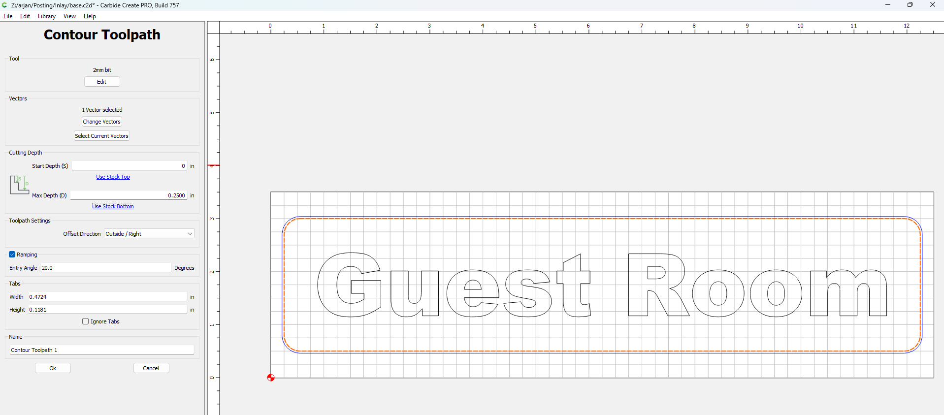
Then click OK to move on to the second toolpath.
The 2nd toolpath is an “Advanced VCarve” toolpath. First select the “Guest Room” words, and then click on “Advanced VCarve”.
A few key things to select: Use the “Enable Area Pocket Tool” option, and select the same bit that you used in the previous contour toolpath.
Then select which V-bit you want to use (in my case, my 20 degree V bit).
Also set the depth of the cut to 0.200":
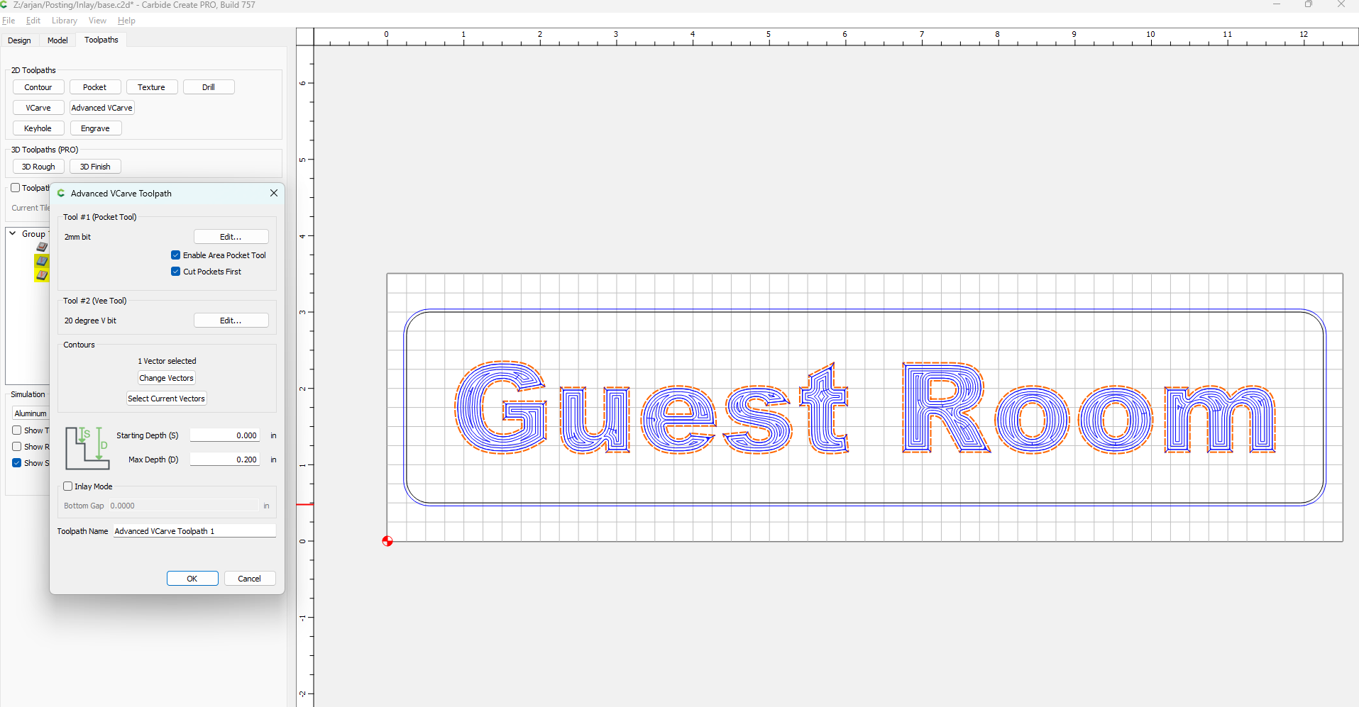
And then click “OK”
The 3rd toolpath is ALSO an Advanced VCarve toolpath, virtually the same as the previous one, but with the “Enable Area Pocket Tool” option cleared:
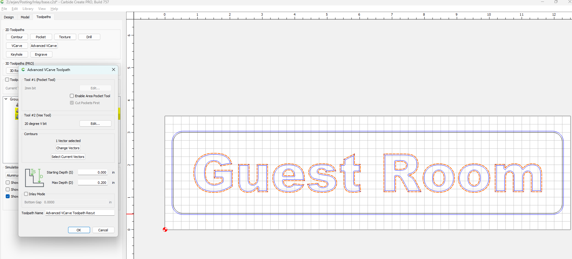
This is technically an optional toolpath, since it will just cut the same thing as the previous toolpath, but I’ve found that I get extra accuracy by doing the V-carves twice. Because it’s basically cutting air, I often tweak the Feedrate and/or depth-of cut on this path to keep the cutting time smaller.
With this, the digital design of the Base is done… but we’re going to cut the Base after we cut the Plug, so on to the plug
Designing the Plug
The plug design starts from the file we just created, so use the “Save As” feature to create a new file from the existing design (I like to call my files inlay--base and inlay--plug).
Go back to the “Design” Tab.
Step 1: Flipping the design
Since the plug goes into the base “upside down”, we need to mirror the design; this is the most important, but also easiest to forget step!
To do this, first use the Ctr-A key combination to select all elements in the design,
and then use the “group” button to group everything into one group:
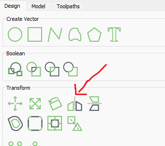
Once everything is grouped, use the mirror button to… well, mirror the design:
The reason to group everything is to ensure the design as a whole gets mirrored, rather than each of the individual elements in place.
After mirroring the design, ungroup again using the same button you used to group the elements; you’ll see an “X” through the icon indicating that it will ungroup.
Step 2: Creating a contour
Now we need to create a surrounding contour around the business end (“Guest Room” in mirror) of our design. We need this for practical reasons (we’re going to do advanced Vcarve, so we need something to vcarve in) but also it’s geometry. The design we have on the digital side is matching the design at the top of the base. But when we put the plug into the base, we don’t want our cut to be exactly flush, but we want to have a bit of spare material to work with… which means we need to cut out a bit wider than the strict design. How much? One can do fancy trig math. Or we just pick 0.25" and overkill it a bit (but make it at least the equal to the depth of your design).
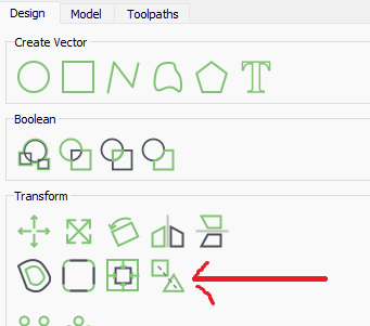
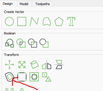
To do this we pick the offset tool:
and do an outside offset of 0.25":
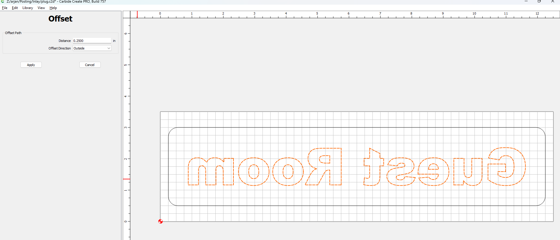
Your design now should look like this:
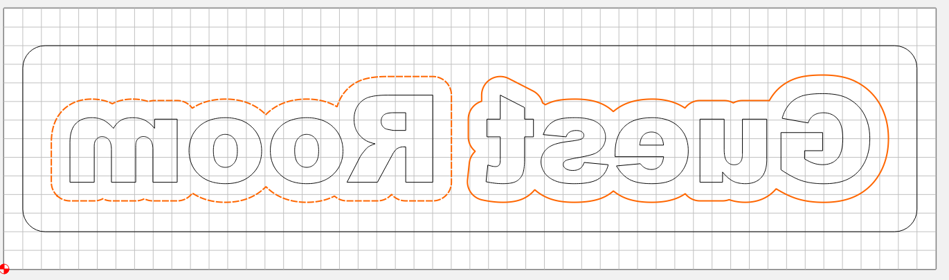
I did not hit this here, but if you have large openings in, say, the letter “O”, that the offset tool gets you little “islands” in the middle of your design. It’ll generally be best to just delete those from the design, especially if they are small.
With this, we’re done on the design tab… let go make some toolpaths.
Step 3: Delete previous toolpaths
Because we did “Save as”, we inherited some toolpaths from the base design… Delete all of these.
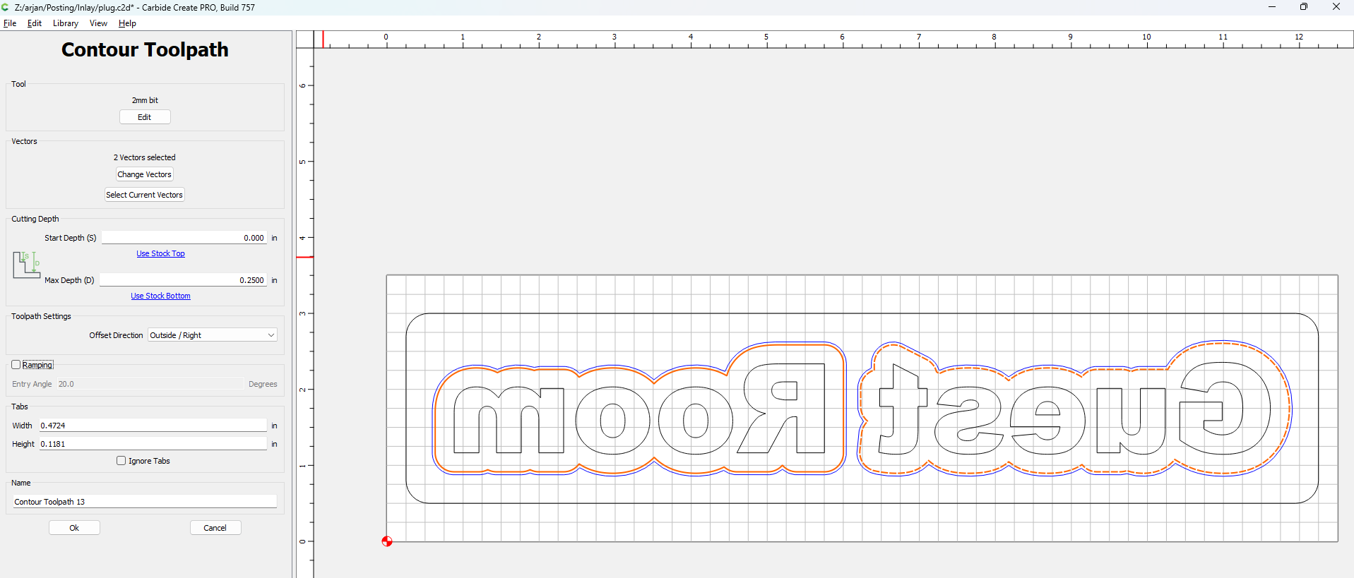
Step 4: Almost cutout toolpath
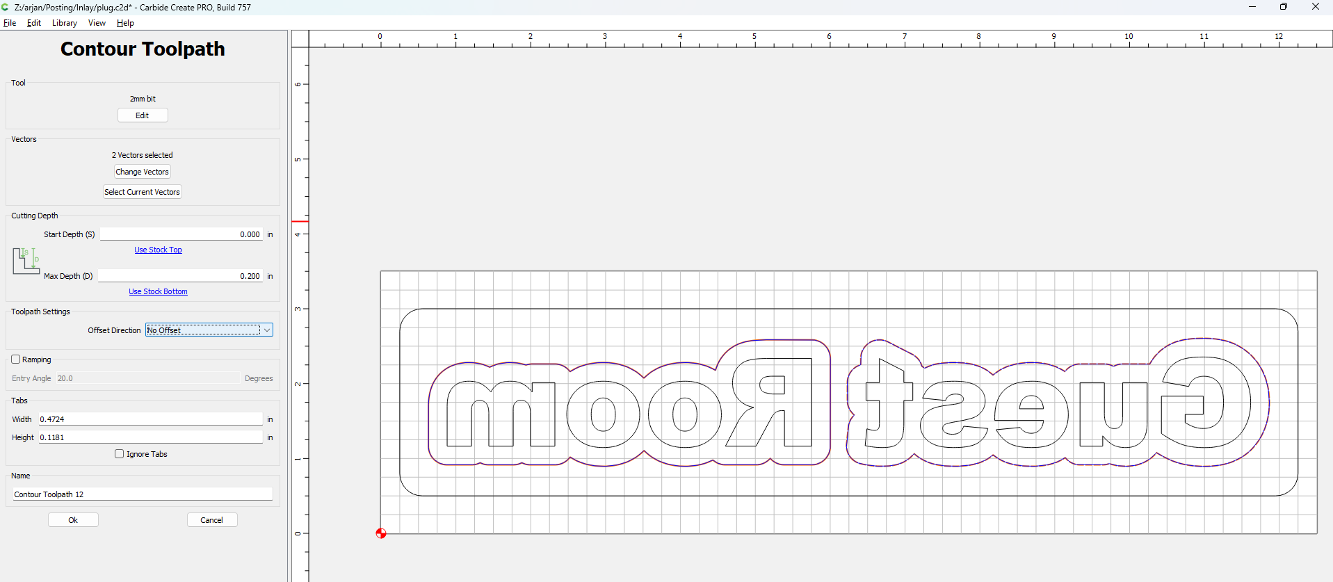
To make the V carve a little easier in the next toolpath, I like to make a contour toolpath that is exactly on this offset element.
With the just created offset design elements (but not the text) selected, create a contour toolpath with a depth of 0.2" and set to “no offset”:
One could be tempted to go all the way to 0.25" depth and cut out the design here, but I would advise against this. In the next few steps we’re going to be removing a whole bunch of material and workholding will be a challenge if you do a full cutout here. We’ll do the cutout as the last step.
Step 5: Advanced VCarve
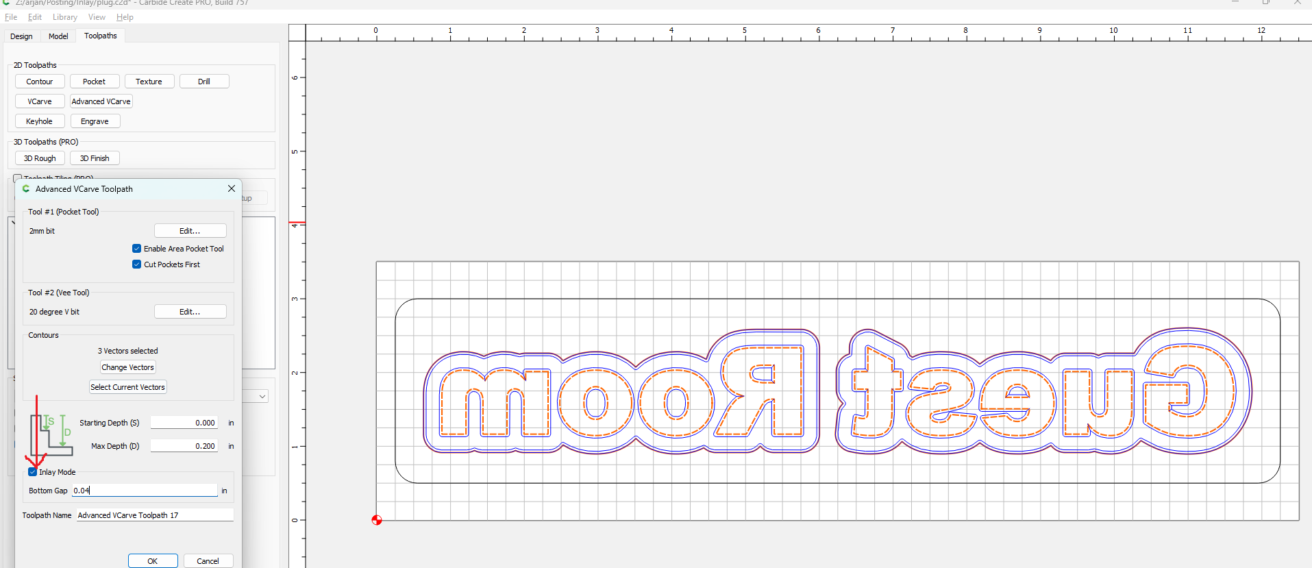
Now select both the offset elements and the text, and we can do an Advanced VCarve toolpath
(the main toolpath for this operation).
As before, we select Area Clearing with our flat endmill, our V bit and a depth of 0.2".
But in addition, we need to select “Inlay mode” to tell Carbide Create that this is the plug for an inlay.
We also need to add a “Bottom Gap” of about 1 mm (0.04"). This bottom gap is also sometimes called a glue gap; it’s a place for glue to squeeze into as we assemble the design… and it gives us a bit of room to get a perfect fit as well.
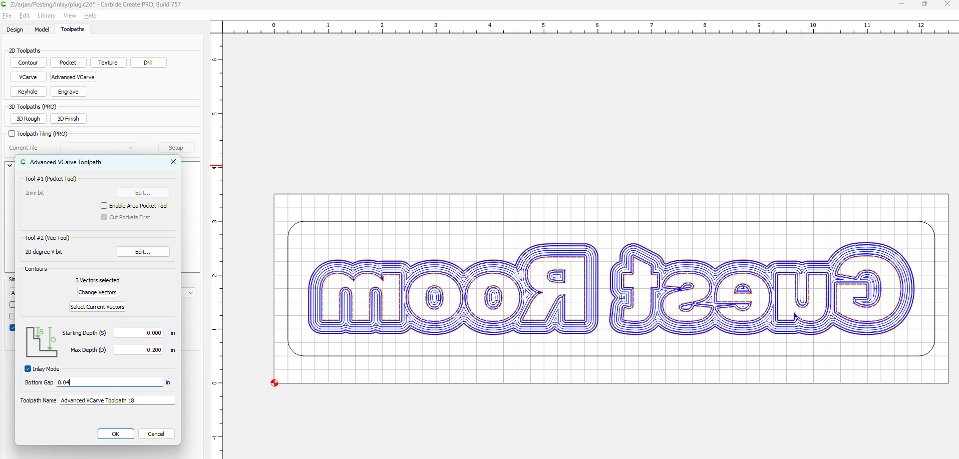
Step 6: The second Advanced VCarve
As before, I like to run a “cleanup” pass for advanced vcarve (with faster F&S), which are the exact same settings as the previous toolpath, but with the Area Clearing option unselected:
Step 7: The cutout pass
As the very final toolpath, we’re going to cut out the design. For this, select just the “offset” elements, not the text and do a Contour toolpath.
The depth will be 0.25" (“Use stock bottom”) and this will be an outside contour cut.
Cutting with carbide motion
All the digital design is now done, it’s time to cut the two files with Carbide Motion. I would strongly suggest to cut the plug first; that way you can test fit the plug into the base, while the base is still in the machine with all the zeroes etc set.
Just load the Carbide Create file into Carbide Motion, set the zero on your material and… cut like normal.
Your outcome should look very much like mine did:

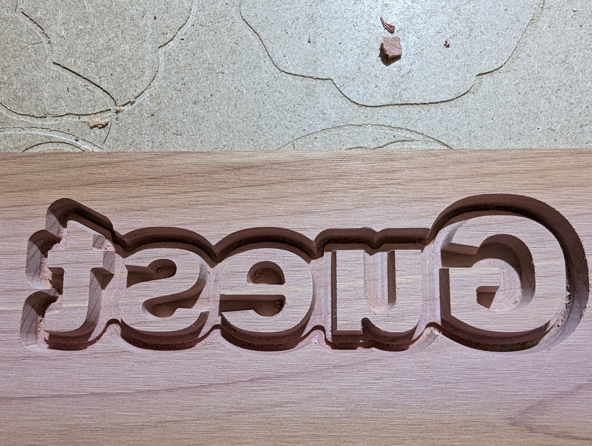
If your cut has some fuzzies or similar, it’s important to clean these up, they will interfere with the glue phase later on if you leave them. I tend to use a toothbrush for this, toothbrushes are a great tool for this since they’re designed to clean in small nooks and crannies after all.
After the plug, follow the same process to cut the base design.
Mine looked like this:

I had to do some minor cleanup with the toothbrush after I took this picture.
Before removing the design from the machine, you can do a test fit with the two plug pieces to see how well they fit; if the fit is not great you might need to repeat the 2nd Advanced VCarve toolpath for a bit more cleanup.
The Glue phase
Now it’s time to glue to plugs into the base. Apply wood glue to the sides of the VCarve in the base, and not to the flat bottom. (Remember that 1mm space we’re leaving, putting glue on the bottom won’t actually help, but will take up the space we need for the squeeze-out to go). I use a small art paint brush for this. Make sure you cover all the sides and corners; a missed corner can lead to tear-out later.
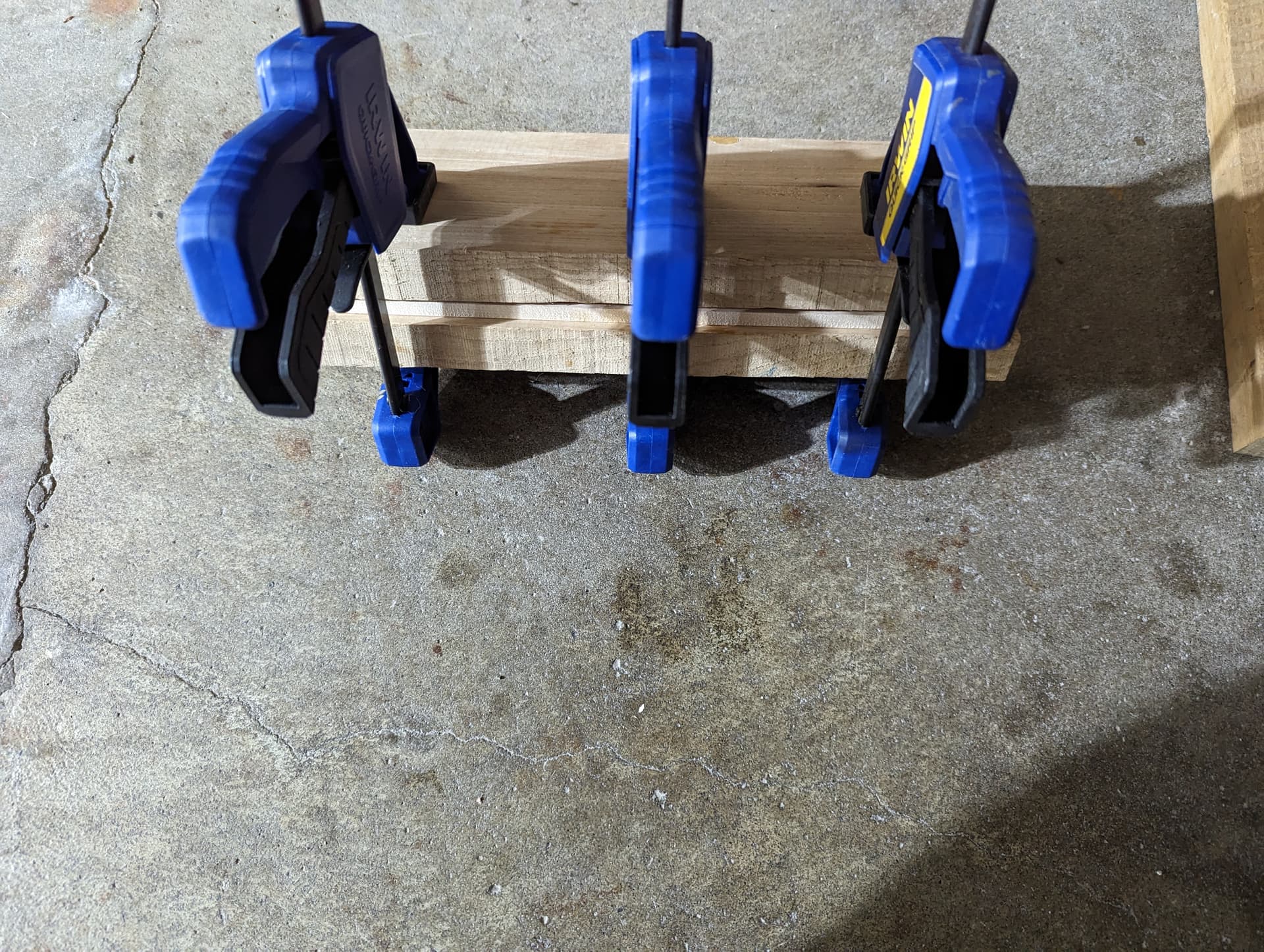
After applying the glue, put in the plugs. An important thing is to not put clamps or weights directly on the plugs; there is a 1 mm hollow area underneath them and if you put a clamp on the plug directly, it’ll deform and you get an awful fit.
The best thing I have found is to put the design between two bigger pieces of wood, and clamp that; the two bigger pieces keep the plugs flat and will distribute the force of the clamps more evenly, avoiding deformation.
It’s important to let the glue fully dry, since we’re going to be cutting the top off next, and if the glue isn’t cured enough yet the machine will just pull parts of the plug out again, destroying the work.
Cutting away the top
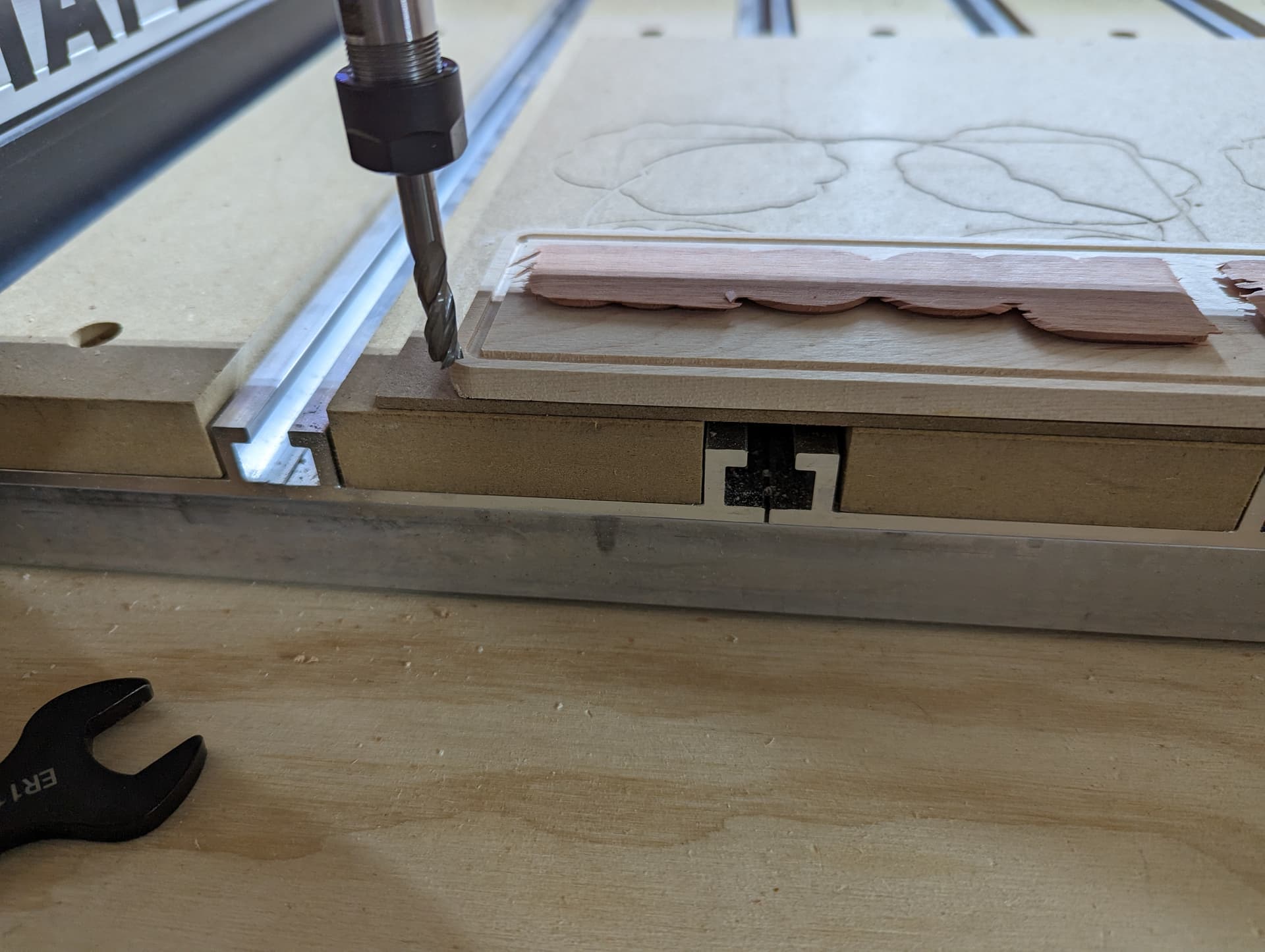
When the glue is dry, put the now combined piece back on your Shapeoko and we’re going to cut off the excess material.
It might feel a bit tricky to set the zero; it’s important to set the zero at the top of the base material (not at the top of the plug), see my picture below:
The digital side for this step is simple, but it depends on if you have Carbide Create Pro or the regular version.
Our base piece is 12" wide by 2.5" high, so we set the material size to this:
And then we create a rectangle that is oversized (12.5" by 3")
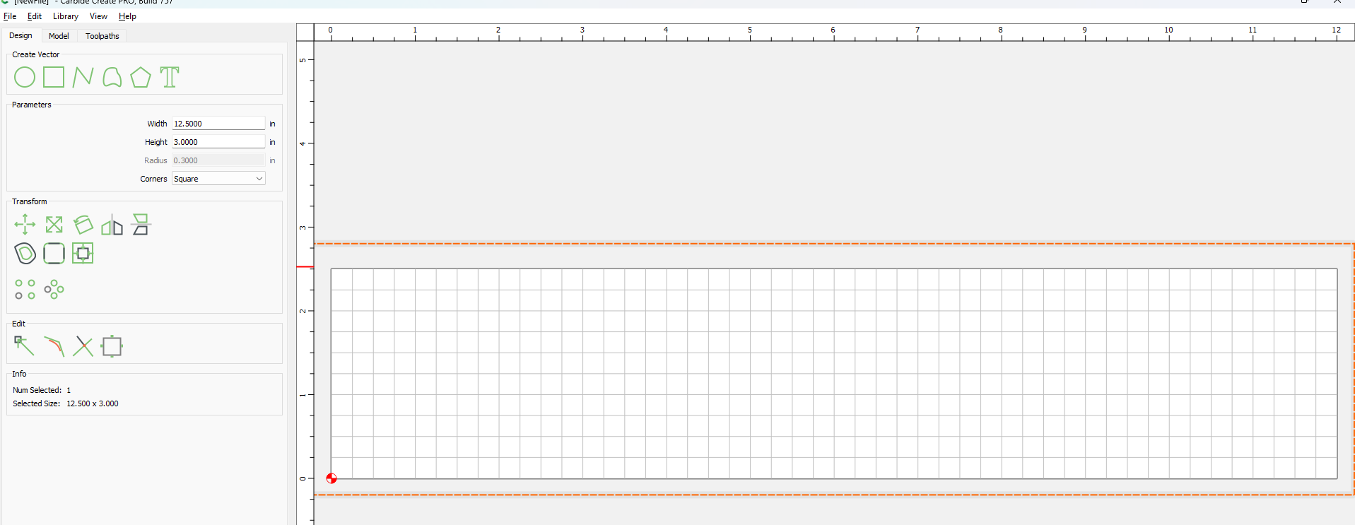
Arrange the rectangle such that there is a bit of space around all sides of the design. While it’s not critical that this is precise, you can use the alignment tool (as we used earlier) for this… or you just eyeball it.
Now for the toolpath, this is where the regular CC vs Pro difference comes in.
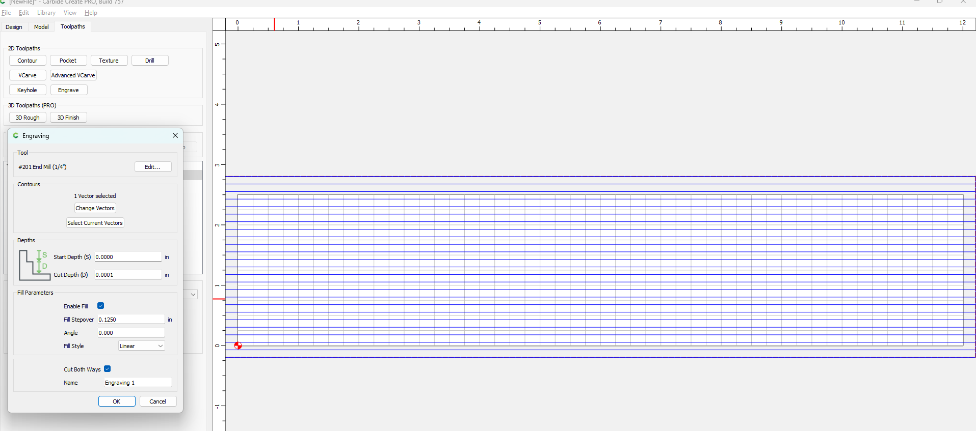
For CC Pro I’d like to use an engraving toolpath, while for the regular CC you just use a pocket toolpath.I’ll show a screenshot of both cases.
Because we are zeroing on the top of the base, we want to not cut away anything, but to make sure Carbide Create actually creates a toolpath we need to have it remove 0.0001"
An engraving toolpath (CC Pro) will look like this (and I would suggest potentially using a larger bit for this, say a 1/4" inch #201). Here I set the stepover to 0.125", depth to 0.0001 and the angle to 0, to get nice parallel toolpath lines. If you have many fine details, I would suggest reducing the 0.125" stepover to maybe half that to reduce the risk of tearout.
A normal pocket toolpath (regular CC) will look like this:

In terms of feeds and speeds, I would suggest going a bit slower than normal, again to reduce the risk of tearout.
Load this file into Carbide Motion and run it.
As the very last step, I normally use a normal orbital sander with 220 grit paper to smooth out any toolmarks from the design, and apply some walnut oil to the design…