Community challenge #28: Return of challenges

Oh that’s a great idea! I’ve been wanting to try some colored epoxy.

You may lose the depth variation using epoxy unless you use a semi transparent pour or do multiple pours with the shallow first and the carve and pour the deeper. That may have too much of a defined edge to look natural.

If the color difference isn’t important to you then just cut it all the same depth and save some epoxy.

I have only begun my epoxy adventure so maybe there are other techniques to achieve the desired result.

2 Likes

I appreciate the advice. I was wondering if the epoxy would be like candy paint where it gets darker each layer added.
My first thought was to do the deeper part a darker epoxy and then the shallower part with a lighter blue epoxy. But I wondered if the top layer would cover the lower layer. I’ve been watching reels of guys doing epoxy tables and from what I saw it always looks like they do clear above the objects they place in there so maybe would be more like a base paint and just cover.

I guess if I do epoxy I loose the depth to the lake. But I think the epoxy would look cooler.

It would definitely be good to get the perspective of folks more experienced in the epoxy world to chime in. I have done some rudimentary multi color stuff but have gone for opaque results in those cases. I have seen some really fancy stuff out there though.

Im relatively new to epoxy, and certainly for this type of work. But, what you said is pretty much my experience. If you practice with your mix, and use powder colors in your epoxy, what you will find is the powder coloring will settle to the lower levels and give it a darker appearance. Its good to test different depths in your stepdowns, and different mixes in your epoxy before doing it for a customer or final product. Pouring multiplelayers always works too. Pour a darker layer in your lower levels, and a lighter, semi transparent layer for the shallow depths.

1 Like

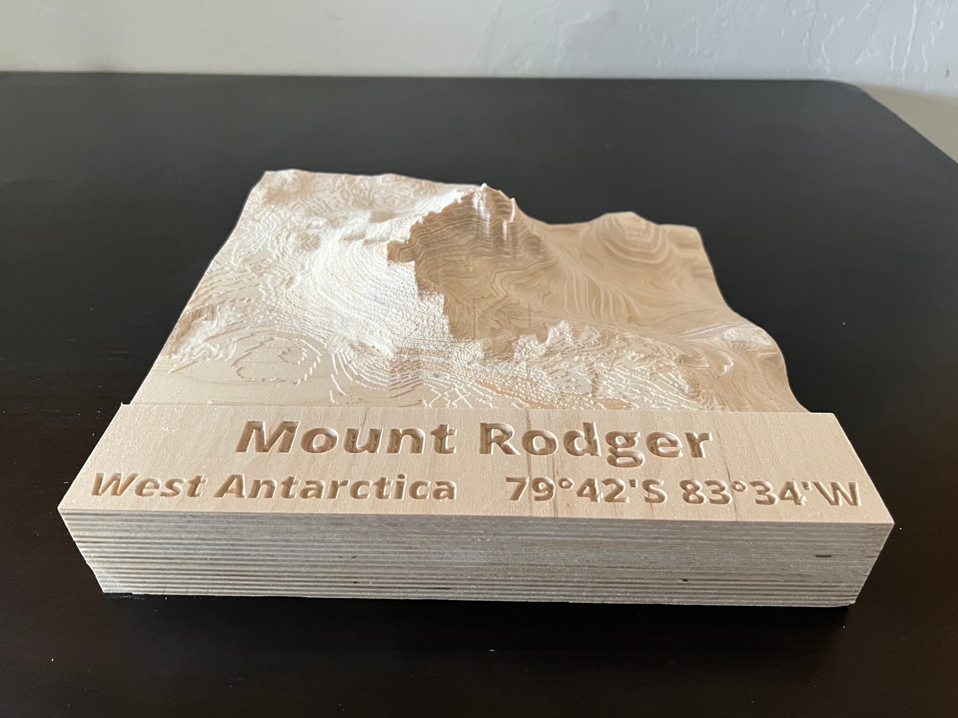
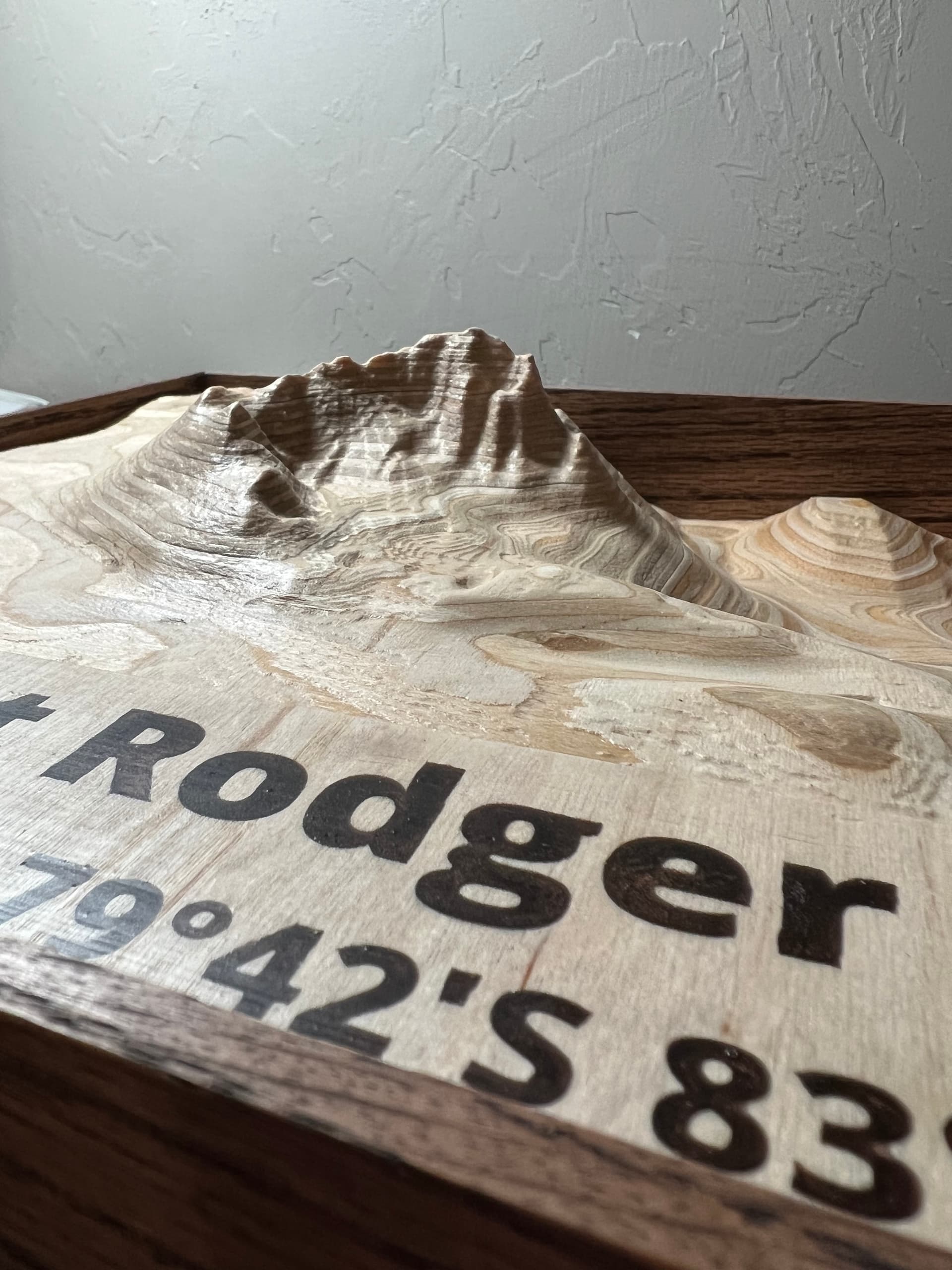
Here’s the TLDR (Too Long Didn’t Read): 12” by 12”, 3.5” thick topographic map of a mountain.


My father-in-law is meteorologist that worked for the US government for over 50 years. The only person I know that moved to Oklahoma because of the tornados. He also lived in Antarctica for over a year, and has a mountain in Antarctica named after him. However he has never seen the mountain in person.

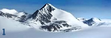
I found this Wikipedia page Mount Rodger - Wikipedia , and many years ago he was emailed a photo from a mountain climber…
5MtClimber

Turning to the internet I found the US Geological Survey created from air photos taken by the US Navy…

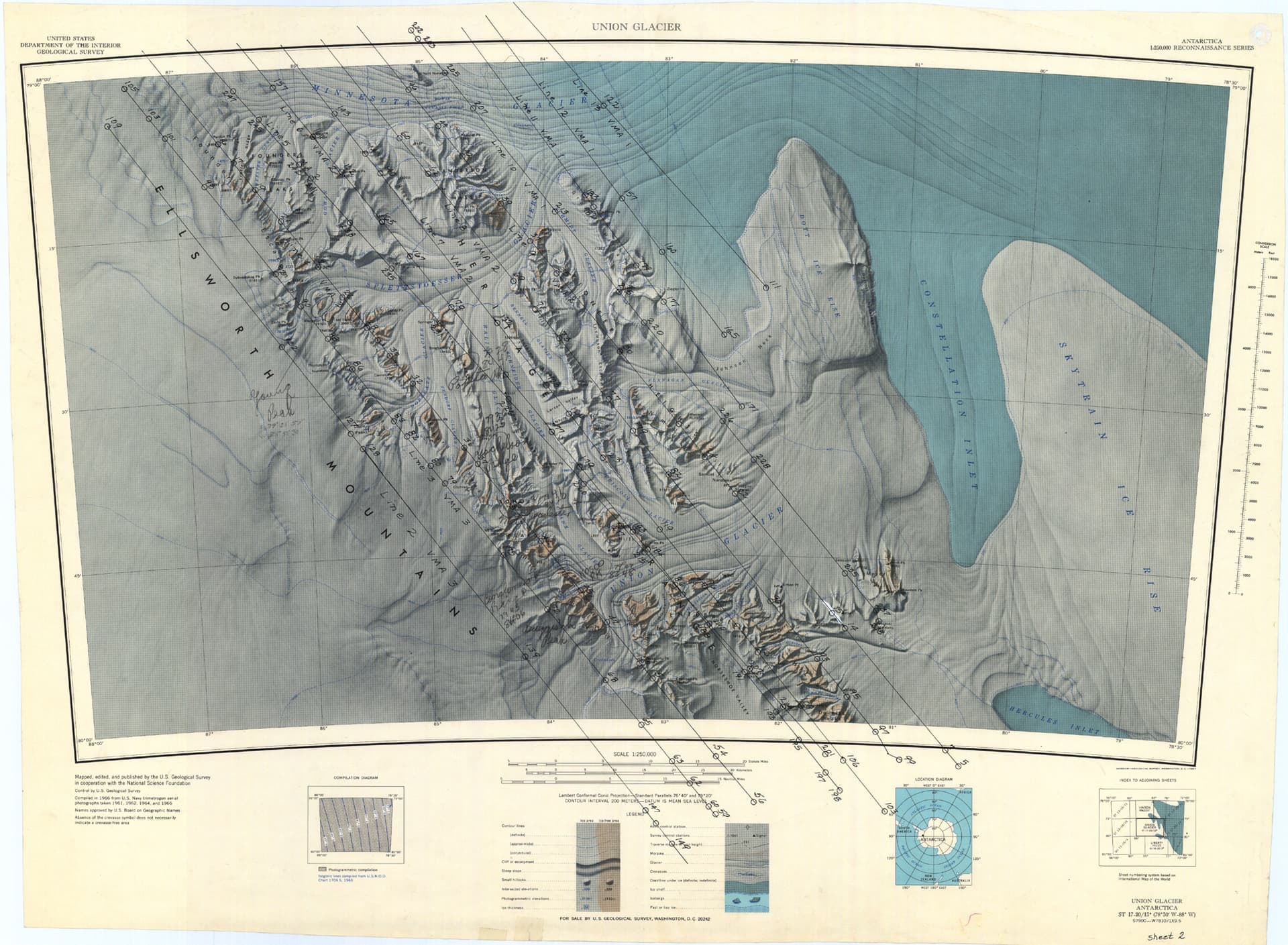
And then started looking at maps using the GPS coordinates on the Wikipedia page…

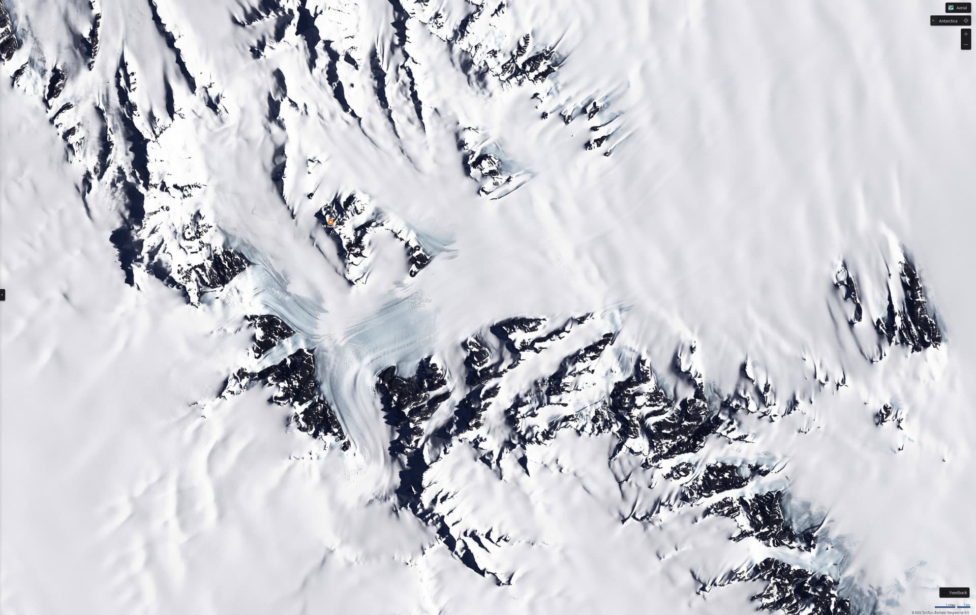
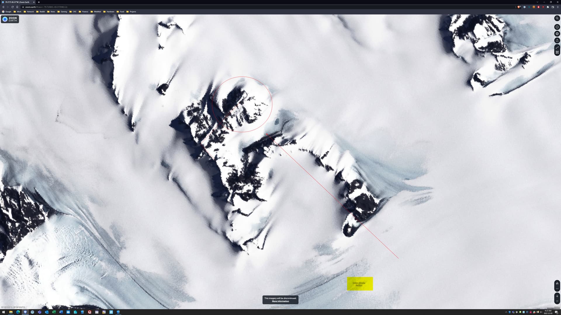
The GPS coordinates put an “X” on map, but after looking at the topographic data and comparing it too all the other information we determined the “X” was in the wrong spot, after all not everything on the internet is correct.

Comparing several photos we determined Mount Rodger was actually the peak North-East of the “X”, and the orientation lined up with the mountain climbers photo, which we also determined was taken while standing near “Union Glacier Station” which is the name for the spot where people could camp during the summer…


With that knowledge I could finally start the CNC design process. With the documented height of the mountain at 1410m, I calculated the correct height-width ratio, and came the conclusion that 3 ½ inches tall by 12 inches wide would be my stock size.

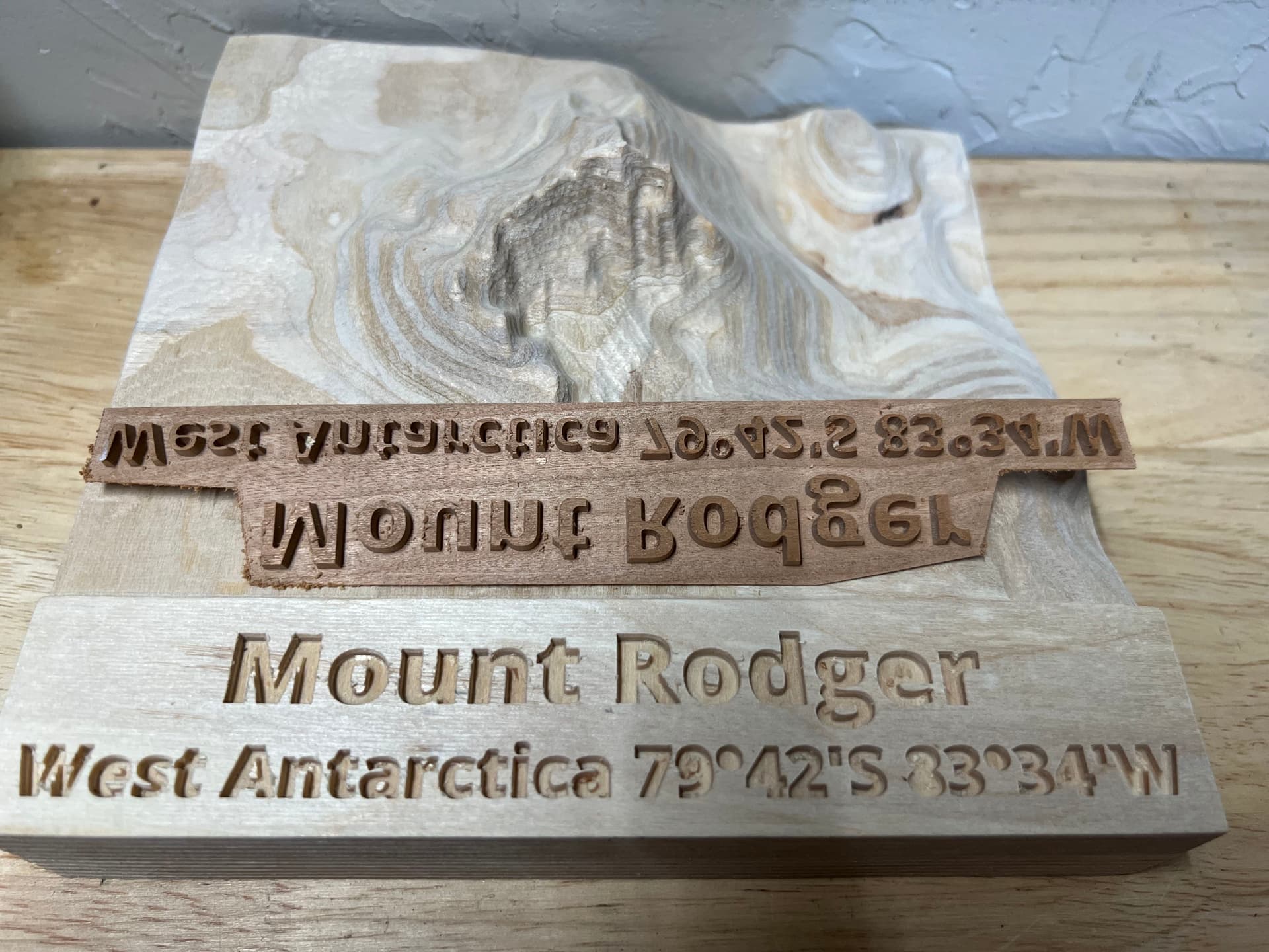
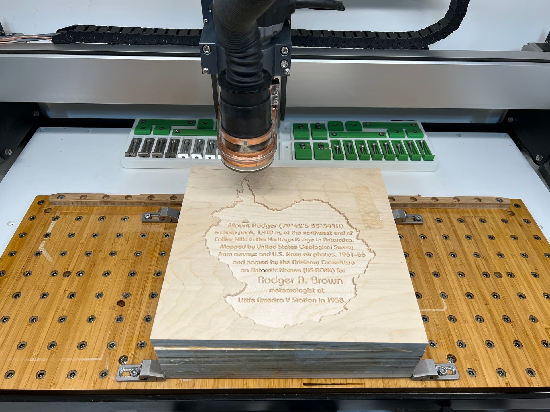
Using Carbide Create Pro I imported the topographic data from Tangram Heightmapper as a Carbide Create Component, then created another component using the “Merge Type Equal” option to artificially create a flat surface 2 inches up from the bottom. I would use this surface to add the text you see in the photos.

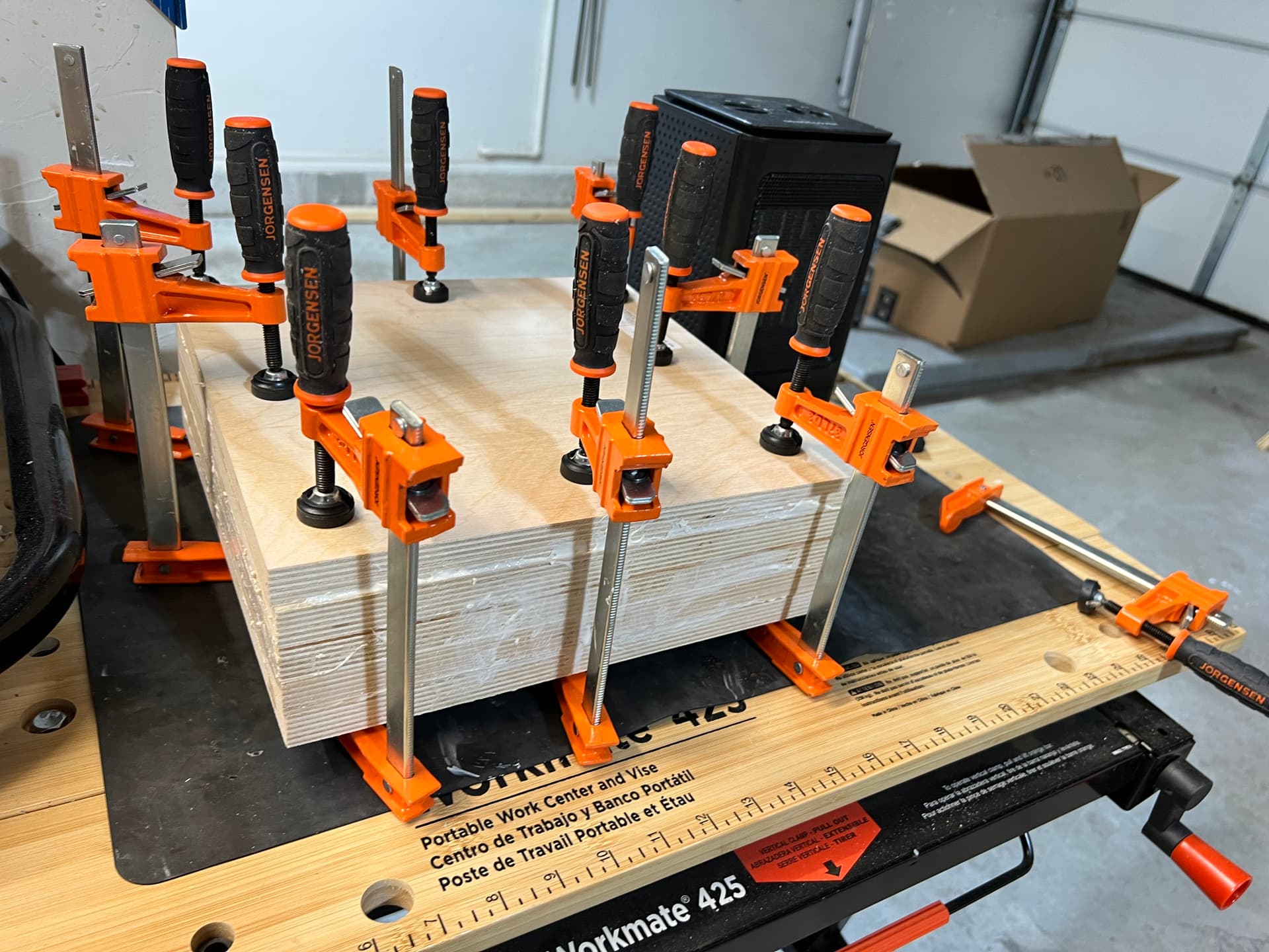
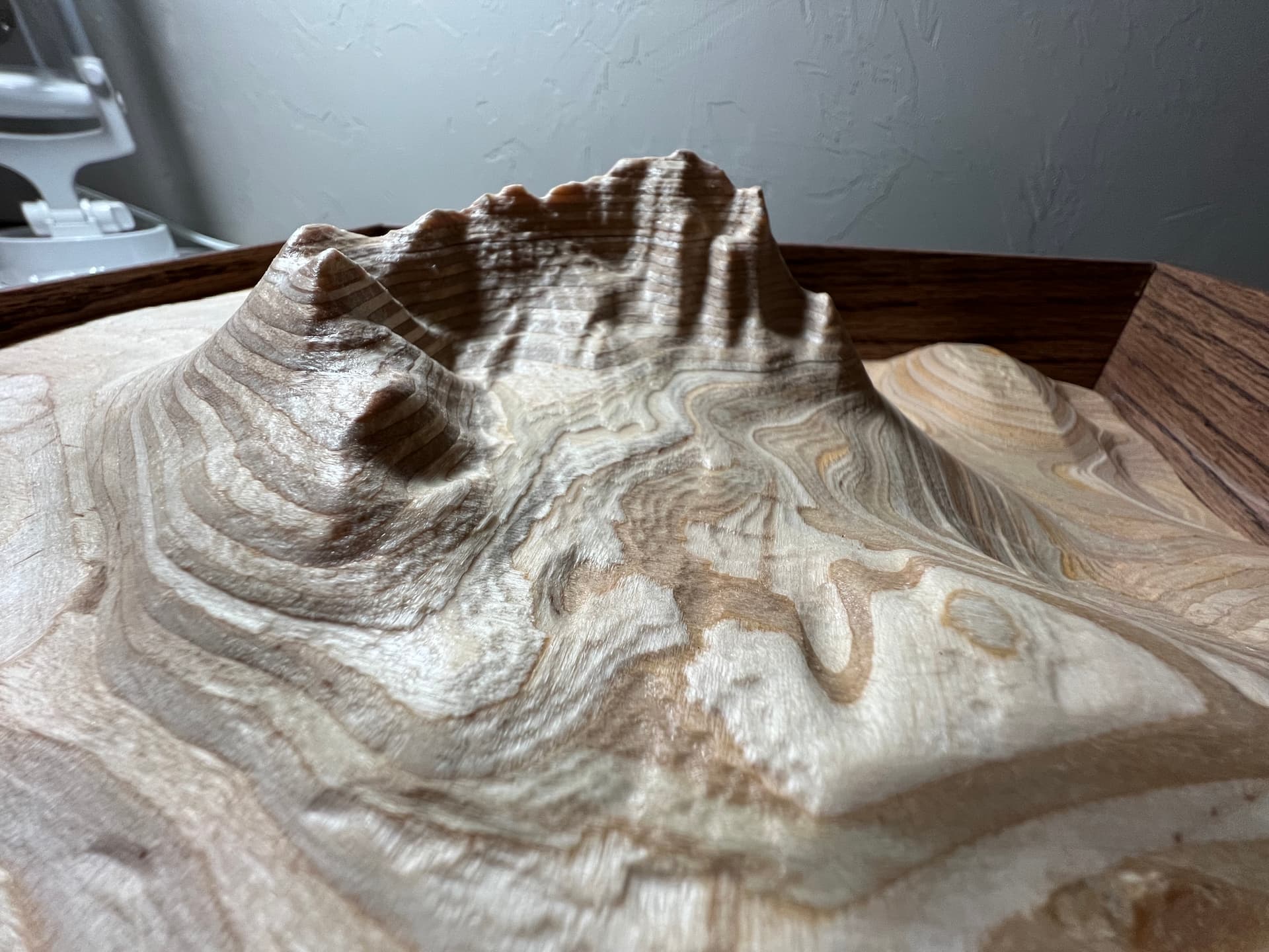
I stacked five 12x12x0.7” pieces of Baltic-birch plywood. I really like using Baltic-birch because the layers in the plywood result in a “topographic line” like manner in the final product…

Which just fit under the Shapeoko gantry without having to remove my wasteboard…

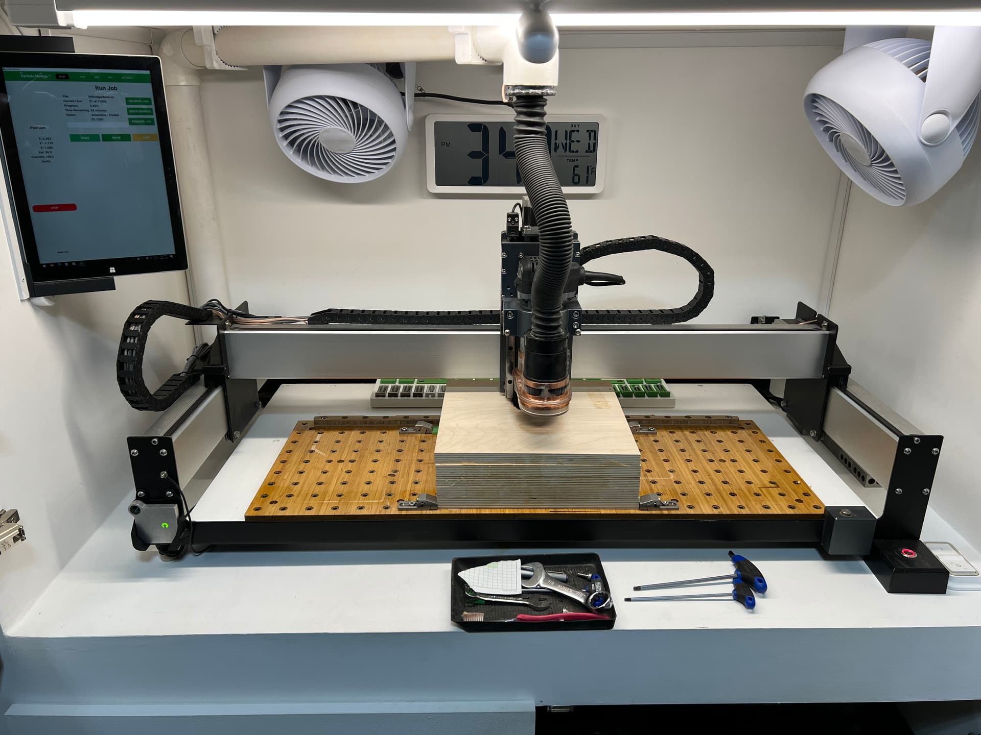
I started by adding a (secret) message to the underside…

Then flipped it over and started the long process of 3D roughing with a 1/4 down cut bit…

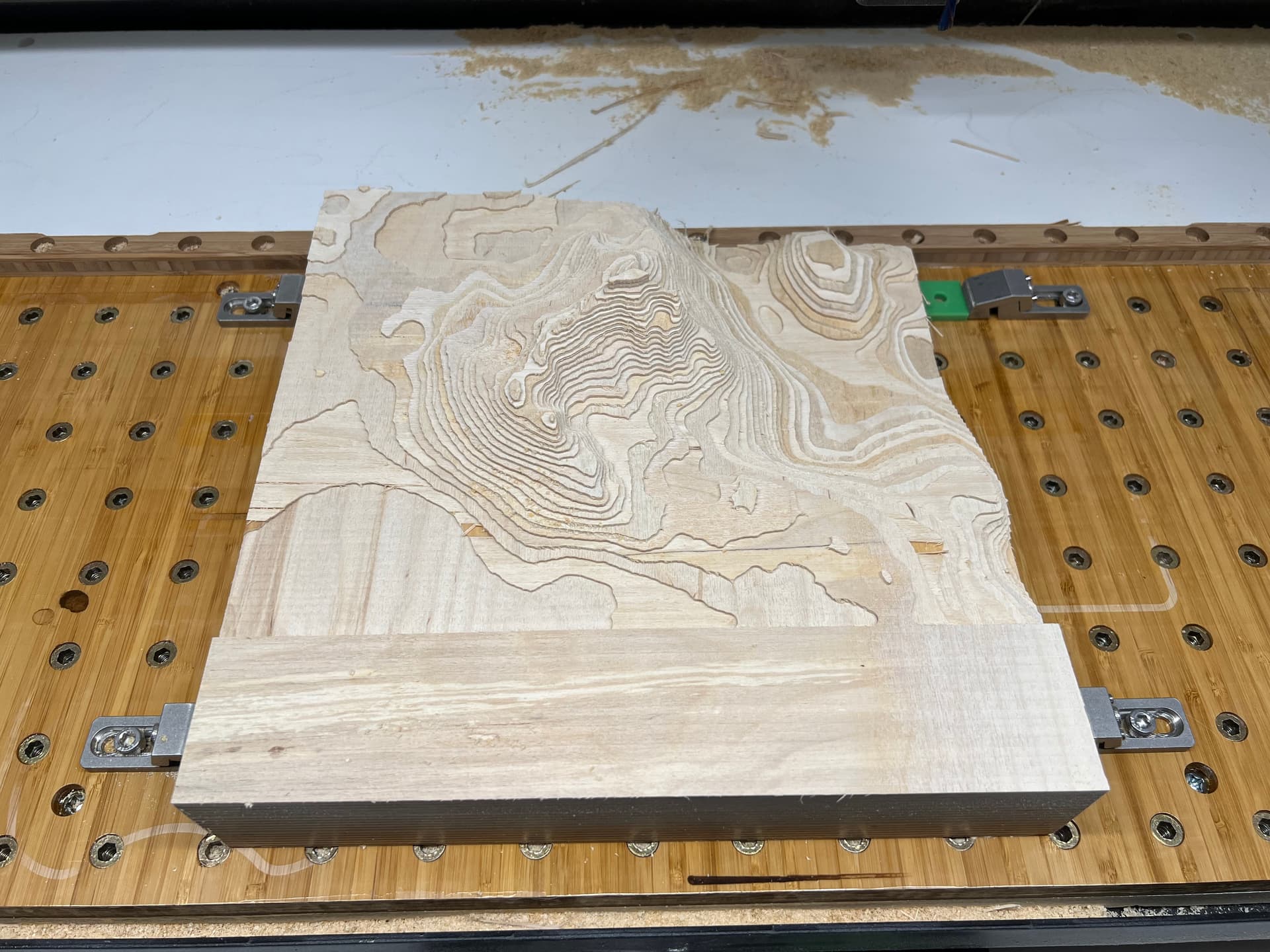
Followed by a 3D finishing with an 1/8 round bit…

I wish I would have weighed the starting stock and compared it to the weight of the result. I suspect 30 to 40 percent of the original wood was removed.

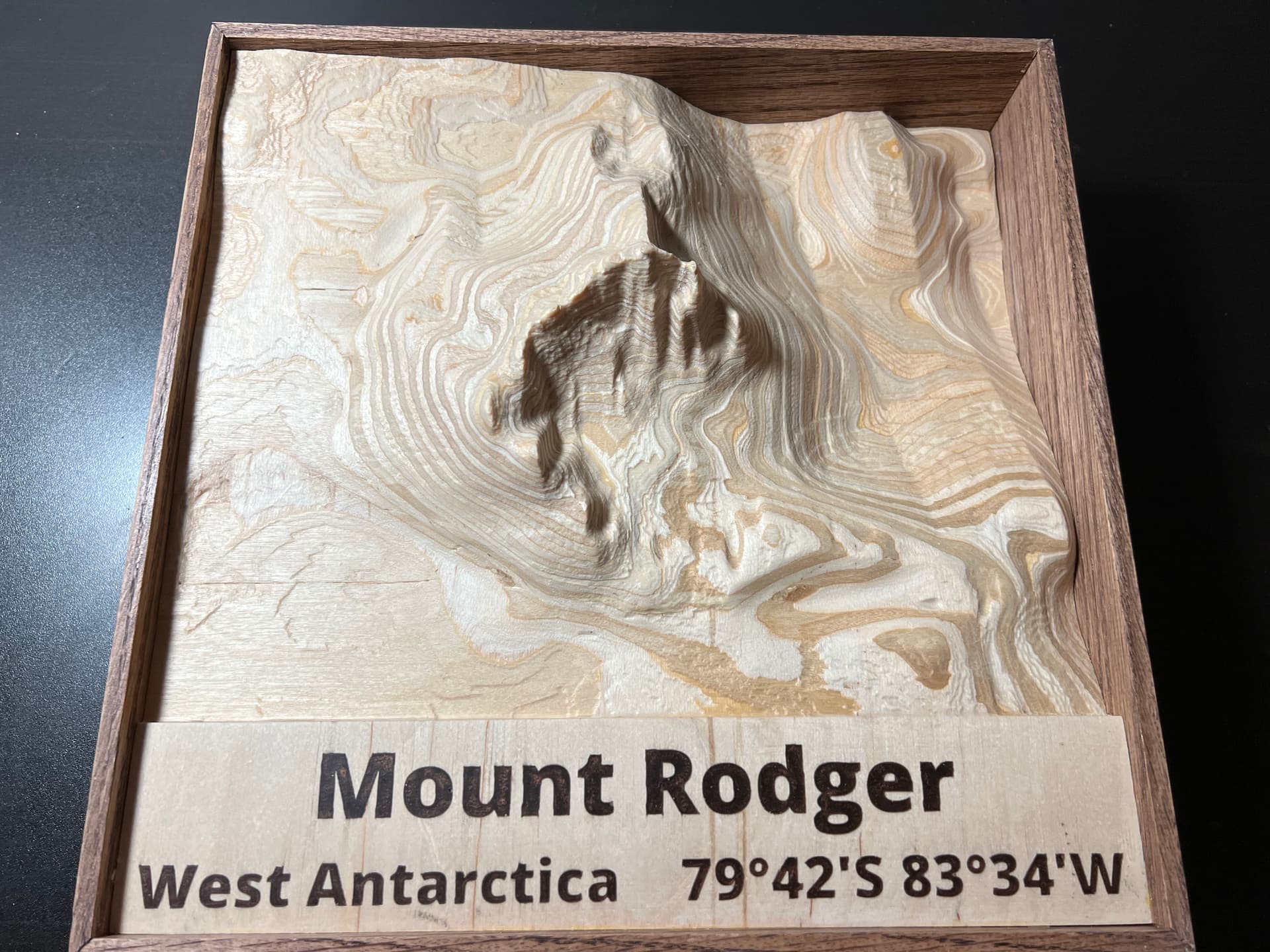
After sanding, and sealing, and some epoxy I added a frame…

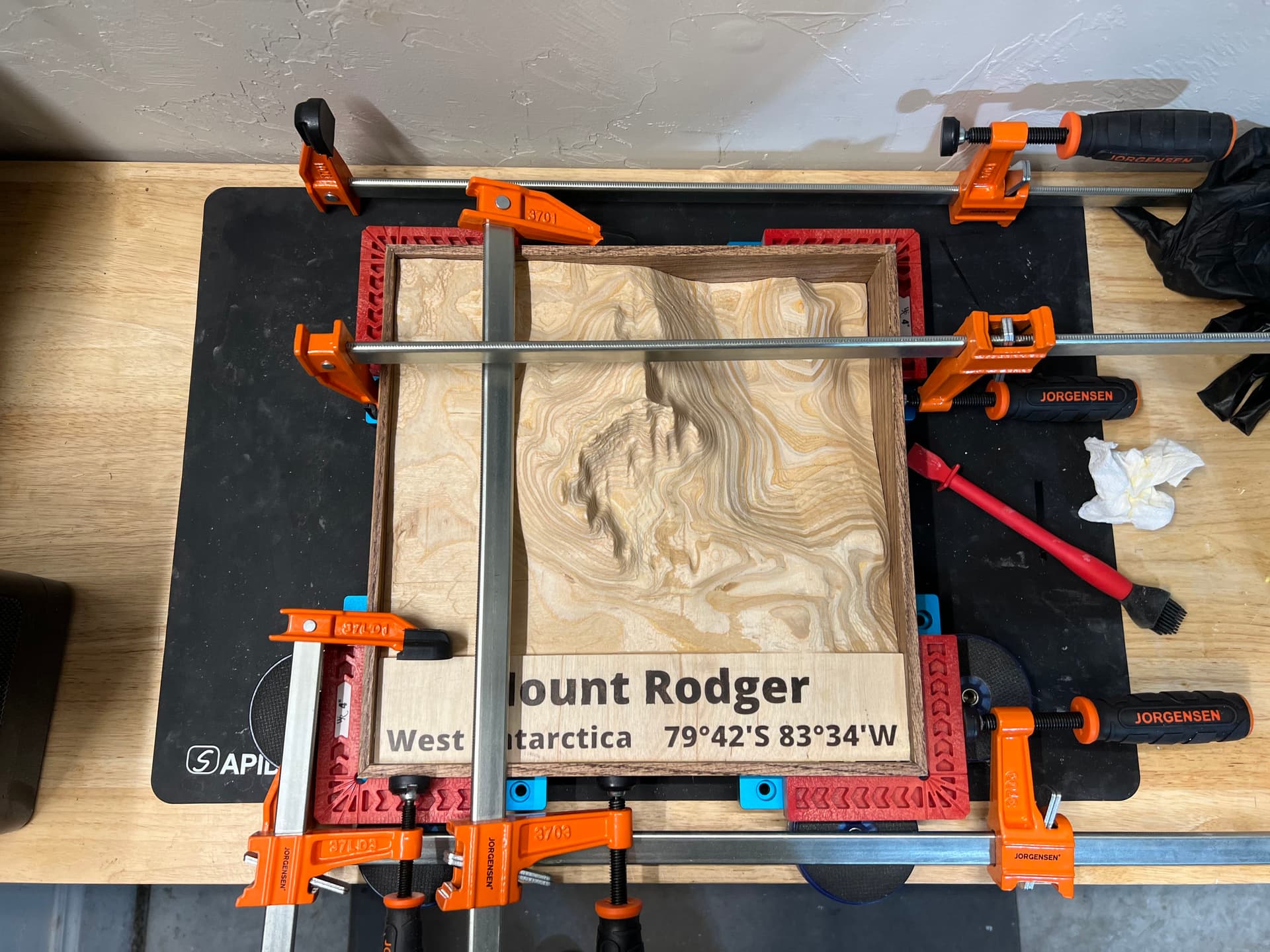
I like that the mountain is taller than the frame…

And it can be either hung on the wall, or sit on a desk…

I’ve created a lot of interesting things with my CNC, but this has been the most enjoyable to make. My wife has requested that I make smaller versions for her, her sister and brother. So I’m currently in the process of making three 60% size versions with plans to try the new inlay feature instead of using epoxy for the name.

Due to the single attachment filesize limit the following attachments are multipart zip files.
MtRodger.zip (14.1 KB)
MtRodger.z01.zip (1 MB)
MtRodger.z02.zip (1 MB)
MtRodger.z03.zip (1 MB)
MtRodger.z04.zip (1 MB)

– Update –
For the 60% size versions I’m using the Carbide Create inlay mode (thank you @fenrus for your tutorial). I’m pushing the Baltic-birth beyond it’s ability to hold small details, but I’m really impressed with Carbide Create.

28 Likes

I love the layered look of the stacked ply. Great idea!

1 Like

Less than a week left!

1 Like

Topography - check
Inlays - check

ok you got me how could I resist.

I decided to make a plaque of the state of Oregon with inlays (walnut into a much lighter wood)… and pondered what would happen if you would, instead of just machining away the backend of the inlay plug like one normally does… you would carve a 3D topographic map into the back of the plug.

Ok so step one is always making the plugs; by doing the same steps from the tutorial, with a 20 degree V bit and 2mm regular endmill, it was more or less standard


inlay-oregon-plug-text.c2d (176 KB)

Then the state map; since it’s much bigger than I normally do inlays, I went with my trusted 302E 60 degree V bit and a 1/8" area clearing tool (for the plug) and went for a 0.25" depth.


inlay-oregon-plug-state-v2.c2d (2.3 MB) (Disclaimer: In my actual cut it turned out I used a copyrighted image for the state outline, so I replaced that with a public domain version for the c2d file here to avoid trouble)

Then it came to cutting the base, and unfortunately I did not take a picture of that… but it was again mostly standard following the tutorial. The only unconventional thing i did was use a 1/4" bit for the area clearing of the state to reduce cut time significantly.
inlay-oregon-base-v2.c2d (2.4 MB)

And then came the fun part, the 3D model. TouchTerrain did not disappoint and in no time I had a nice STL file of the whole state (due to the ratio of the size of a state versus the heights of mountaints, I went with a 3X Z amplification).
It was slightly tricky to make sure the 3D model of the state lined up with the SVG outline… and the only way I got this to work was to first do the 3D model, and then size/align/locate the SVG as best as I could on top of it; one needs to do this in the plugin base file since the size of that state SVG is used for the plug as well.
Now for the toolpaths it was interesting; the plug material will be above the base material and stick out by 0.25" (the material was 0.75", I cut the base of the plug 0.25" deep so I assumed 0.5" was left but I forgot the glue gap in that math… thankfully I had that set very small).
This was easiest to model in Carbide Create as 0.5" stock, with the zero at the bottom… this allowed me to reuse the same zero throughout the whole process.

First I removed extra material that sticks outside the state lines from the plug by contouring with a 1/8" bit (sturdy) and then a 2mm bit (fragile)… then 3D roughing with a 1/4" bit 201, and for the final finishing pass I used my R=0.5 (1mm diameter) tapered ballnose. At first I started to do this in the left-to-right direction. Big mistake… it was the same direction as the woodgrain so it was a big stringfest. Aborted the cut quickly, changed the toolpath to have a 90 degree angle and… no more strings.

inlay-oregon-3d-v2.c2d (2.2 MB)
(same disclaimer on copyrighted material)

Next step: finishing with a bit of walnut oil and … project finished


18 Likes

started last night! …it’s fine … I’m not worried, you’re worried :sweat_smile:

1 Like

I live by ‘if you wait until the last minute, it only takes a minute to do’ rule more often than I’d care to.

7 Likes

Really like the detailed explanation, very helpful for us wanna be like @fenrus !

I make Key Holders with custom locations on my Shapeoko 3 standard. I started with the Tail of the Dragon, but have since added v-carves for the text. The next step, since I ran out of time, would be adding maple inlays for the text for a nicer contrast. My .c3d file won’t upload since it is bigger than 4mb, here’s a drive link: boulder-CO.c2d

Lessons learned:

  • Tighten your collets if you’re going to have more aggressive feeds, mine came loose and chewed right through my corner bracket.
  • Make sure your stock is square! My Tail of the Dragon stock is not square and I didn’t notice until after I hung it up on the wall.
  • I manually put a keyhole in the back for mounting, but could have used Carbide Create to do it instead.
  • I wanted to make this file with beginners in mind who likely have the starter set, #201, #102, and the 60 degree v-bit were used along with the #112 1/16" ballnose due to the nature of this challenge being topography. I’d recommend upgrading to Cody’s Jenny bits in the future since you can be far more aggressive and the tapered ball nose bits make a huge difference.
  • Use a tooth brush to get the mountains oiled, makes life a lot easier.


12 Likes

I really like all the designs where the topography is raised above the surrounding stock. It really adds depth to the finished product. Well done.

1 Like

I took my idea of topography to a different place. The Moon. 3D is the goal, but for me to get started 2D was a lot of fun. Thanks to everyone who posts questions and anwers. Ive done a lot of reading on here and thats what made this possible at this point. The project is 26" X 26"

The view will be from the Earths Moon. The moon and Earth have been designed on CCV7 on a Shapeoko 5.

The Moon is created on plywood. The craters have been stained with Samon - Ebony 318 stain. The crevasses filled with 200 ml of Beaver Dust - Silver grey resin. The Moons surface is then done in 220 ml of concrete and covered in 200 ml clear resin.


The Earth was made from plywood. The water is Blue Pearl Dry Resin. The underlying clouds are silver mica powder. The top clouds are Titanium Dioxide mix with only part ‘B’ resin, then blown around the earth with a heat gun to make the effect. Then a final top coat of 200ml resin.


The Stars were dollar store metal tiles for backsplash. I left them somewhat raised but feel i should have sunk them in further.

Key holes are done but i did those on my router table due to time. Although once i get faster the cnc will be my main way to acieve that on these projects.

The backing is again plywood. Simple boarder. Again stained with Samon Ebony 318 stain. There are pockets for the Stars and the Earth.


I would like to add to this project and change different things. Over all im crazy happy with it. Im not sure what i can say for the mistakes because i sort of just rolled with it and what ever came of it i was happy with.

I learned a lot about the cnc. A lot about the community here and the help and excitement for others. I hope you enjoy the pictures.
Thanks for your time,
Michael

  • If anyone wants to know anything i will be pleased to answer. I will try and get this file up. (So much involved in this texnology for me).
10 Likes

Where did the moon image come from? Ive been wanting to do some moon topography. Im a bit of a space nerd. Ive tried figurimg out the US geological data for the moon, but so far ive been unsuccessful with getting something i like.

1 Like

It was simply a google image. Both the Moon and Earth were google images. Love Space Thank you for your interest.

Maybe I should add the picture of the crate that my entry shipped in upon arrival at my customer’s home! Well, to add another lesson to my lessons learned, over built crates are clearly not enough, you should triple build your crates when shipping. They clearly played a game of see if we can drop this in as violent a manner as possible at some point in the shipping chain. Will not know if there was damage until Sunday. Fun times.

1 Like

I am a new CNC user - started 60 days ago - and wouldn’t have considered making anything for this challenge until I started looking at all the great things people are making and how they explained the process.

Reading about the Grand Canyon project and checking out the links Jarrad provided caused me to give it a try and see if I could figure out the process.

The website link to get a topo map file is great and I chose an area in NW Colorado where I have been visiting for 65+ years. I had a scrap piece of 8/4 poplar wood so I gave it a try and was amazed how well the machine can carve it out.


The cut was 1.5" deep and after doing the 3D rough cut I realized that the 1/8" ball bit was too short to cut that deep so I had to round up a longer bit so I could finish it. I shut down the machine and disconnected my laptop for a day and when I came back to it I had it jog to the XY location and it went back to the correct spot so I proceeded with the finish cut with no trouble.

After it was finished I painted in the lakes and streams and then stained the poplar so it didn’t look all light colored.

I had a piece of maple so I had the machine cut in a pocket for the topo to rest in and added the text with a vcarve path. Font is the national park font that a previous post had a link to.

One other piece I just made was a knife holder for a family member. I put a pocket of the map of Arizona into it and added copper colored epoxy since Arizona is the “copper state” In the pocket the machine carved out a raised symbol which is their agriculture brand.

I wanted to figure out how to cut the box joints on the machine so was able to rig up a material holder on the front of the machine secured to the t-track slots. It worked out well considering it was the first go at it. The knife holder is made of maple and alder at the top.

I really appreciate all the helpful pointers and suggestions folks have as they answer other peoples questions. I wouldn’t be this far along without being able to read all the comments. Great forum.

9 Likes

I’ve actually had this project in the wish list for a few years, but never had a driver to set aside the time to learn how to do this all. Community challenge pushed me along and I’m happy with the result.

In 2017 2 friends and I hiked for 5 days around Dormer Mountain, it was just over 60km which had what felt like 100 water crossings back and forth over the Panther river. It was frequent enough you just give up on changing out of your hiking boots and save your dry runners for camp each night.

I used Terrain2STL and cropped the view to capture the hiking path we took.

This supplied me with a great stl which I used meshmixer to crop out some of the bulk at the bottom.

My friend sent me the screen shot of the gps path we took and where the campsites were which I traced with Inkscape for later use.

I ended up breaking this process into a few different files to keep them straight in my head.

PantherHike.c2d (3.6 MB)
(ignore the bit names in the file, working off a new laptop and hadnt set up my library yet. The correct bits are in this writeup)
The first was the 3D roughing pass done on a 11" x 7" x 2.75" chunk of black walnut. I used my long reach 1/4" ball nose bit to clear out the bulk of the material. I was careful to ensure there was a solid wall around the mountain range so I could later flip over the stock to work from the other side. Since the route was a loop, I added breaks in teh path where camp was each night and used those areas as tabs to hold it all together and later milled those out for decorative pins.


This did take a while… Amana Tool 46294

PantherHike_path_pocket.c2d (120 KB)
The Hiking path was machined from the backside (so flipped the workpiece over and re-indexed and secured down. (Kept the same Zero)

I used just simple vector lines and did each days path at an appropriate depth. I used this bit
Amana Tool 46280-K. To ensure I was milling deep enough I did add a rough pocket first to work inside of.

PantherHike_path_plug.c2d (136 KB)
The plugs were cut out of a 2x4 and hammered home. I used the same vectors (flipped) with offsets on either side for the bit to follow. It mostly worked.

The finish passes next would clean up any plug sticking through.

Along the way I found voids in the walnut so these were touched up with CA glue, later to be cleaned up in the finishing pass as well.

Flip over the stock after gluing in the inlay hiking path and load up the finishing pass file.


It’s cleaning up nicely.

I opted for two finishing passes, so I could do additional cleanup with CA glue in between.
First pass at 45deg, second at 135deg
image

Whipped up a simple frame (24"x14.5"), threw some pictures from the trip around the carving and added some brass pegs to mark the start/end and the 4 camp sites.

18 Likes