Disclaimer: I’ll provide some advice to hopefully steer you in the right direction, but staying safe and not damaging stuff is all on you
Don’t do any of the following blindly, you need to understand what it does and why, and double check everything I wrote. Basically, don’t trust me, I’m a random guy from the internet !
I guess the VFD came with the manual, but I can see how that may look a bit intimidating. Some guy posted a copy of the manual here, so my recommendation below is based on that. There is also that video.
Step 0: adjust GRBL parameters on the Shapeoko
from the MDI command line set $30 to whatever the max rated RPM of your spindle is. It is probably etched on the body of your spindle.
Step1 before connecting anything you need to adjust all VFD parameters
just connect mains on the VFD (to N and L terminals) and power it up.
you’ll need to study the manual to figure out what value to use in each one for YOUR specific spindle, so I won’t be able to tell you what exact values to set for each, but here are a few pointers:
P00.01 must be changed to 1 to allow external speed control
possibly P00.09 to 0 , IF your spindle is water-cooled
P01.00 to 1 to prevent reverse rotation (should not matter)
P07.08 to 3 (to tell the VFD to pick up the external signal on VI1)
P12.00, P12.01, P12.02: you will need to adjust them to your spindle’s characteristics
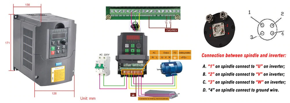
Step2 wiring the rest of the VFD & spindle, which boils down to three things:
output power to spindle
U,V,W to spindle connector
you also need to earth your spindle (if you don’t, you’re taking chances of having severe EMI issues down the line). So find out if your spindle is grounded internally, i.e. is the 4th pin on the aviation connector connected (internally) to the spindle body (with a multimeter in continuity test mode). If it is, fine, run that 4th wire to the Earth terminal on the VFD.
speed control signal from the Shapeoko
locate where you can get the PWM signal on the Shapeoko controller board (depends on the version and on your soldering abilties), run the GND of the shapeoko’s controller to GND terminal on the VFD, and the PWM signal to “VI1” terminal of the VFD
now for the bad news: your VFD has a 0-10V analog input for external speed control, and the Shapeoko outputs a 0-5V PWM signal. You may need to buy one of these converter, or you may be able to tune P03.11 to 512 but the documentation is unclear, this would need to be checked.
forcing the Forward direction of rotation
short the “FWD” and “XGND”
Once you are there, turn on the shapeoko and home, turn on the spindle, it should not spin. If it does, turn everything off and go back to wiring and parameters.
From the MDI command line, send M3S1000, the spindle should spin slowly (1000RPM). Send M5 to stop.
If it spins in the wrong direction, you will need to swap any two wires among U,V and W.
Julien, as a random person on the internet, you are hell of helpful!!
Thank you so much, most of my questions are answered. I will start working on it by tomorrow and will update on my results.
Thanks again!!
Hi everyone,
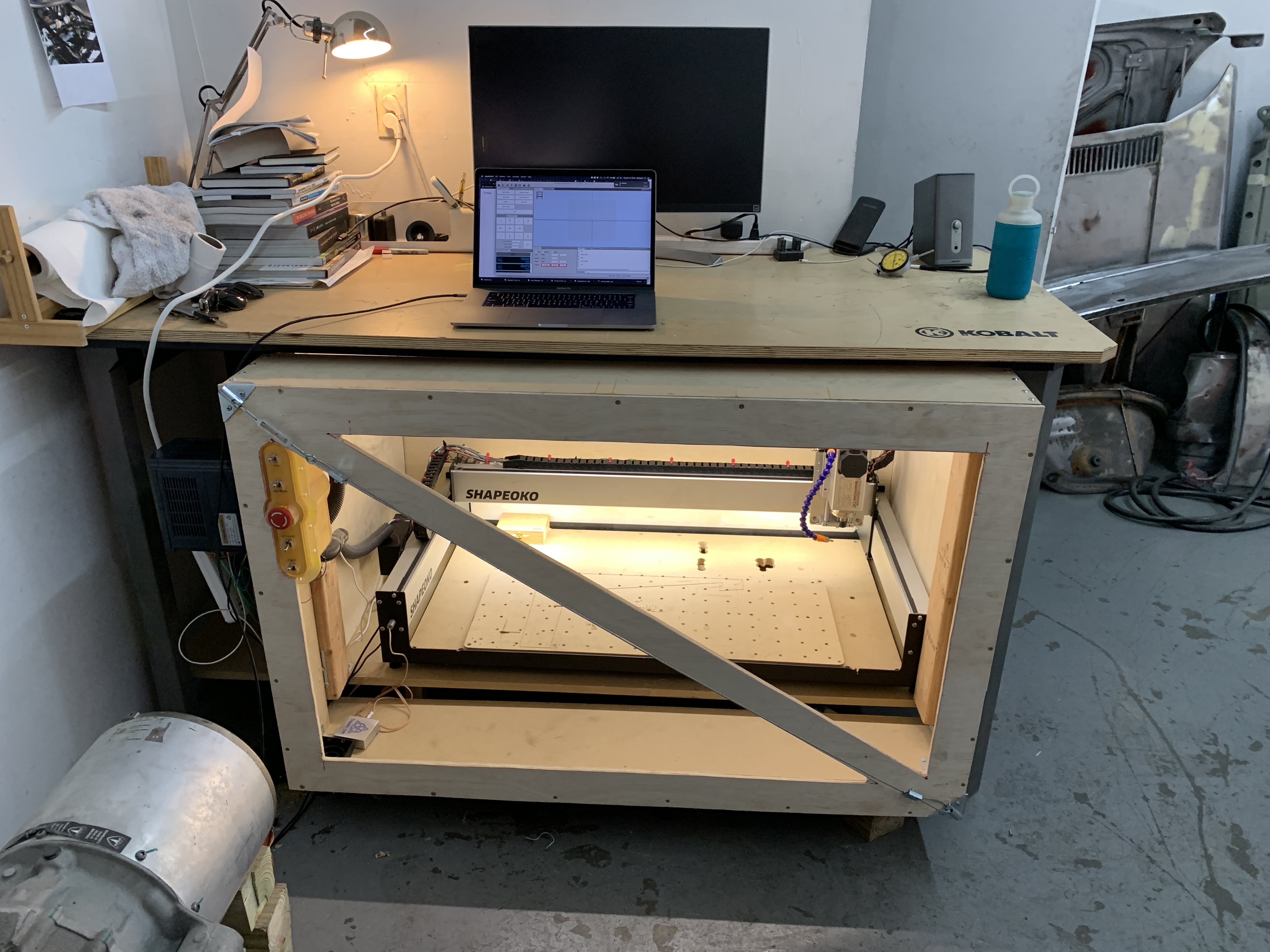
Here is my new setup for my XL.
I upgraded to a 1.5kw air cooled spindle with vfd.
I have a beaver hdz and I am waiting on my steel reinforced belts.
I did all that as I sometimes do very long jobs (10+h) on plastic and the original makita router showed some signs of struggling…after changing multiple times the brushes and getting very very hot at times.
Also, I am about to have multiple aluminum jobs, so I feel some of those upgrades are needed.
I made a custom mounting plate for my spindle which allowed me to go thinner (6mm thick) instead of the original 9mm as I now have four mounting screws for the spindle and not just 2. All in all, more rigid and less counter balance.
However, even with @Julien ‘s help for wiring, I can’t get my spindle to work. He advised getting a 5v to 10v converter from the carbide pbc, which I am waiting for it to be delivered. But, the spindle won’t turn even when pressing “start” on the vfd.
I get a constant “F 0.00” flashing on the display…nothing else.
Would someone have a idea what it means? There is nothing on F displayed in the manual…
Ok I’ll try that. I did, however I did disconnect the vfd from power supply and I think the parameters reset themselves when I tried to spin the spindle (I tried before and after, so there was still an issue). Did I fry the spindle??
Thanks for your help!
I don’t know but let’s start over. Disconnect the spindle from the VFD and we’ll start over.
Lets check the spindle and cable first
Make sure the spindle turns freely by hand. If you have an ohm meter check for continuity across the three wires you disconnected from the VFD. You should have continuity between any two of those wires. If you have a ground wire you should NOT have continuity to any of those 3 wires. Stop here is this doesn’t work. Don’t connect the motor yet.
Speed Control
Your VFD is different from the standard Hy VFDs I’m used to as it does not have any option to accept a 0 to 5v signal on the Vi input. Yours only accepts 0 to 10 volts (only thing documented in the manual). It also does not say it’ll accept a PWM signal or it really requires an analog voltage. I suspect it requires an analog voltage since the manual only illustrates using a rheostat/pot to vary the speed. If that is true then we need to insert somethings in-between the Shapeoko PWM signal and the VFD. We’ll defer this discussion for now and see if the VFD is still working first. Don’t bother connecting the Shapeoko to it until we see the motor spinning…
VFD Settings
Then I think you start by checking all your VFD settings again. Write down any differences from default on a copy of the manual page. Come back and let us know which are different from default. We can double check your work before you reattach the spindle. Make sure you set the VFD to use the internal POT on the front panel for it’s speed control at this time. In fact set it to use all the controls on the front panel so we can start/stop and test it from there.
Test
Once we’re confident the settings are correct we’ll reconnect the motor and power up the VFD. Then try to operate the motor from the front panel of the VFD. Hopefully it’ll work and we can incrementally make changes from something that works
Hi Gary,
Thanks for helping me like that it is much appreciated!!
Yes it does work on PWM I believe, but I need a converter from 0-5V to 0-10V, which I am waiting on it to arrive.
The spindle does spin freely, no issues there.
That sounds like a plan, I’ll keep you posted on the progress.
P03.08 - 0.0HZ (min frequency if you use the potentiometer on the panel for speed control)
P03.09 - 400.0HZ (max frequency if you use the potentiometer on the panel for speed control)
P03.10 - 3
P03.11 - 1020 (this value can be adjusted to tune the spindle speed if you use PWM from the carbide board)
P03.12 - 0.0HZ
P03.13 - 400.0HZ
P07.08 - this is the setting used to select your input for speed control, either the potentiometer on the front panel or via PWM from your carbide motion board. Set value to 0 to use potentiometer as speed control and 3 to use PWM input as speed control). If you use PWM from the Carbide Motion board please remember to change GRBL settings $30=0, $31=24000.
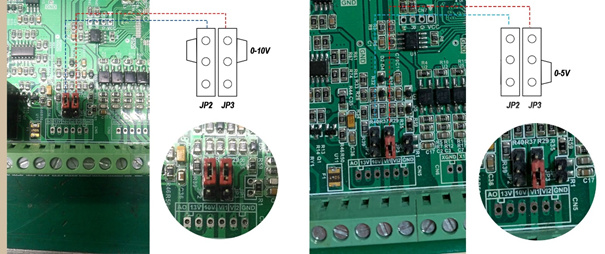
Now time for some good news! Unlike the Hyunhang VFD you can actually select on the main board of the VFD whether your PWM input is 0-5V or 0-10V. If you are lucky you have the upgraded main board with jumpers to easily change this. If not you have to whip out your soldering iron and do a bit of soldering. Either way its a simple task. Have attached some pictures below;
I did short FWD and XGRND but it gave me an error (IPM fault).
Gary, I do have continuity through all 3 wires from the spindle. However, since I do not have a ground wire, would it work by simply screwing a cable on the aluminum casing?
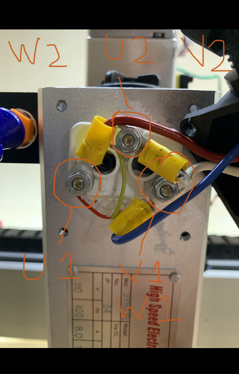
Sindre, I applied the parameters you gave me (know that my spindle is a 110v). Also I do not have the 4 poles goin out my spindle, I have only three, which are wierdly marked as U1, V1 W1, and W2 U2 V2. I wired U1 to U, V1 W1 to V and W2 U2 V2 to W in the VFD.
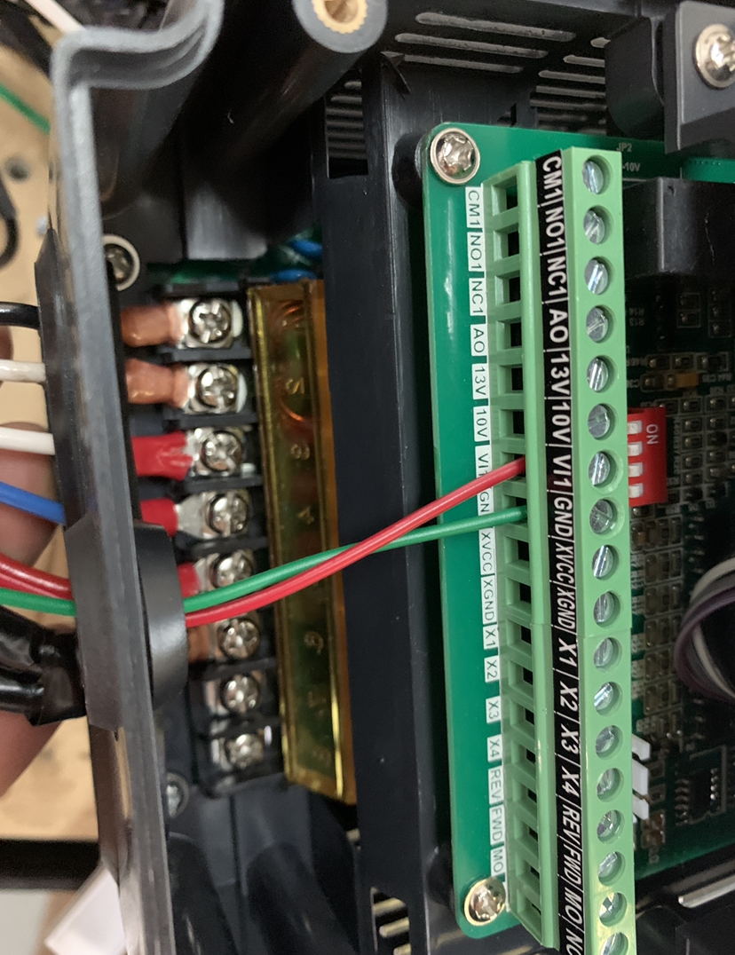
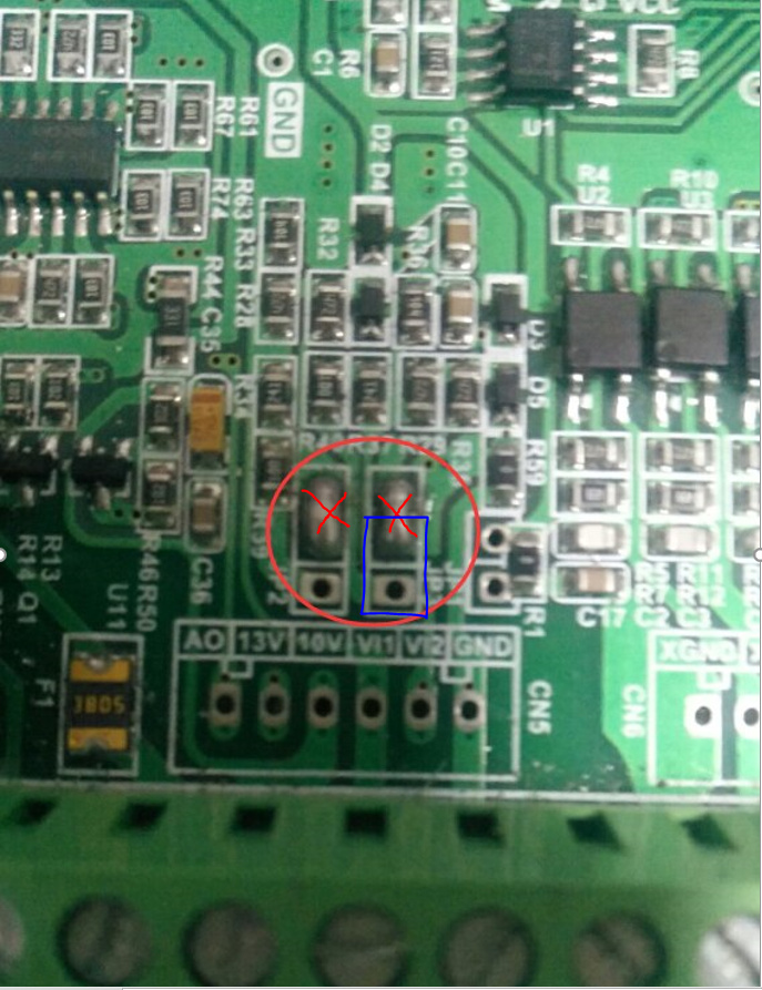
Now for the jumpers, it looks like I have a version updated from yours, with select switches for the JP2 and JP3. Howerve I am not sure how to toggle them right, see picture:
First of all; @wb9tpg is absolutely right about the GRBL settings - thanks for pointing that out.
Re VFD settings - since you have 110V you should change P00.01 to 60.0HZ
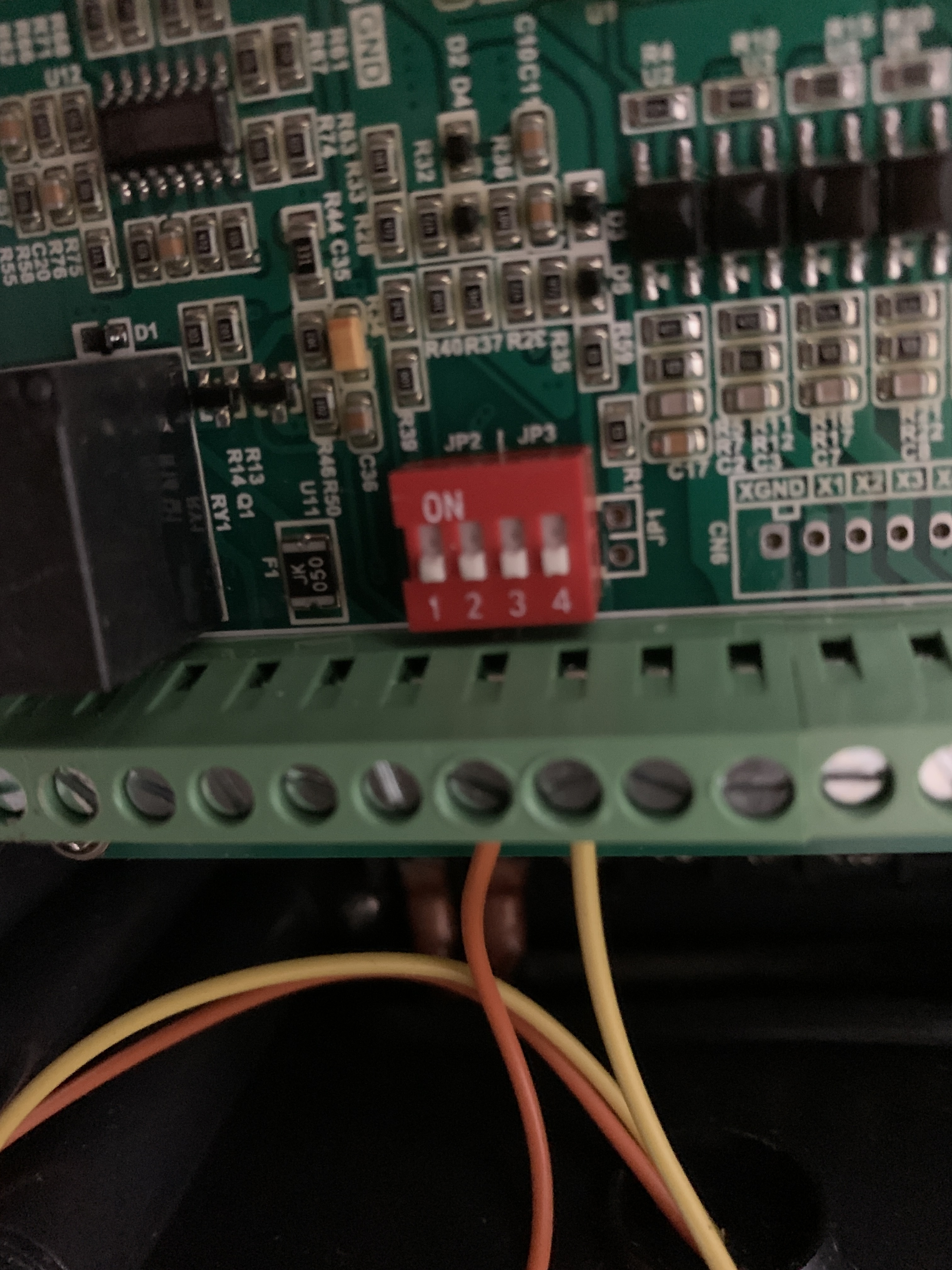
As for your dip switches I did a quick search on the web and it appears that 0-5V mode is selected when all of the dip switches is “OFF” (as they are in the picture you attached).
But before you go any further with the PWM set up I think it may be smart to get your spindle running by just using your control panel. Do you have a wiring diagram for your spindle? Or brand/model number for it? Not quite sure if I understood that wiring labeling you mentioned?
Hi!
So the spindle turns well using the vfd only. However, nothing happens through g codes. I use UGS platform, and also tried in Carbide motion. I sent m3, /m3, m3 s12000, /m3 s12000.
Not sure what to do…