Hi Guys, following on from my thread on upgrading the Shapeoko 3 to a 2.2kw spindle
Here was the discovery with a fair amount of ramblings.
I thought it would be useful to do a full write up on it – so that others can learn from my mistakes and learning’s.
Firstly, why do this? It’s worth noting that an air cooled spindle does not have all the benefits of a water cooled version. Here is why I upgraded to a water cooled spindle:
• Higher torque and lower speeds – better for milling aluminium and some wood
• Much, much quieter – my ears are taking a much needed break
• Greater selection of collets – allowing you to select more versatile end mills (more so in the UK)
• Better accuracy and less run off
• Less heat – meaning wood doesn’t warp when being milled
• Less maintenance – no need to change bushings
• Arguably cheaper in the long run…
You might have other reason, but those were mine.
Now for a shopping list – your going to need to bust your amazon/ebay account for this one.
• Spindle – choose what you want 1.5kw is very much suitable. But for not much more you can have a 2.2kw one to which I see no downsides to buying.
• VFD suitable for said spindle
• Spindle mount
• Pond pump
• 5-10m of 6mm (inner diameter) pipe (I was supplied with 5m, another 5m would be useful).
• Water tank
• ER collets
• 3/4core 1.5mm2 wire – between 5/10m
• Small selection of fine multicore wire – approx. 10m
• Couple of pcb pins
• Box of assorted springs
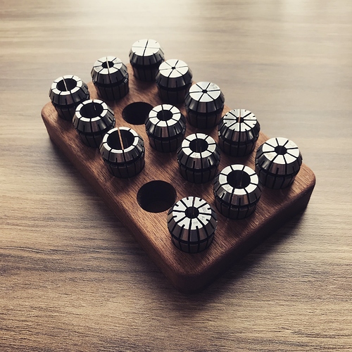
Now I bought a kit from ebay – it was £225 for the spindle, vfd, pump, spindle mount and pipe. The water tank was £7, ER20 collets were £15 for 13 sizes, £8.29 for 10m of cable, £6.50 for the springs and I had the fine wire and pcb pins already.
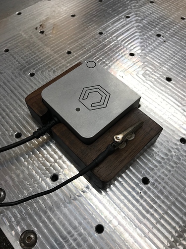
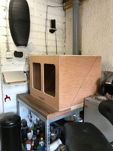
It’s worth noting at the same time I decided to upgrade my enclosure – my previous one was around 44cm high – due to the size of my new spindle I had to re-build it to accommodate for the additional height. I also fitted my carbide touch probe at the same time.
I found this a worthwhile thing to do as it gave me more workspace and I made a few subtle modifications to improve my original design.
Over to the job at hand. The first thing you need to do is remove your Z axis and old router. From there you will find you have 4 holes that allow for the current Shapeoko spindle mount to be position high or low. Using a sheet of paper, position the Z axis and mark where these holes are on the paper, then squaring this piece of paper up on the new mount, transfer them using a die or marker.
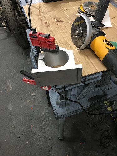
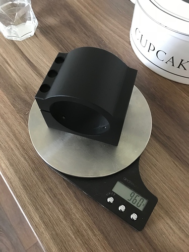
You should have the marking of the holes on the rear of your new spindle mount – CHECK THEY ARE SQUARE. Once you are happy, that they are, drill and tap the holes to M5 spec. You will also have 3 small protrusions on the Z axis, repeat the paper process and drill these out of the rear of the mount with the largest drill bit you have, for me this was 12mm. After this was done I cut the sides of my mount off to save around 100g. You don’t have to do it, but I did, I also painted my mount in black VHT spray paint to tidy up the look/feel.
Take a 6mm drill and drill through the four holes in the z axis plate to clean out any powder coating – this will give you more wiggle later on.
You can now loosely secure the mount to your Z axis and re-assemble. You can tighten up your 4 mounting screws using the holes within the X axis plate later.
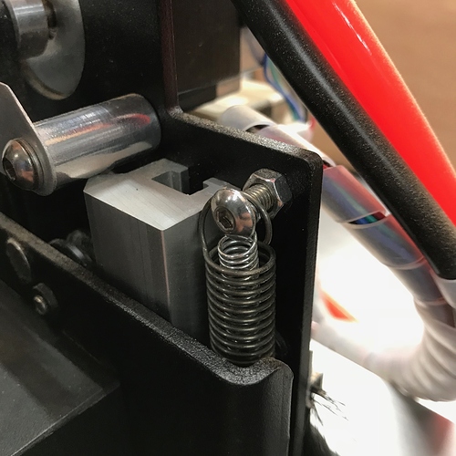
Whilst assembling the Z axis you will need to upgrade the springs – I didn’t have the perfect spring but managed to find similar springs that were half the diameter of the stock springs so threaded these through the inside of the existing spring – doubling my spring tension and almost neutralising the weight of the spindle. If you don’t add more springs you the spindle will drop.
It’s worth mentioning this setup is over double the weight of the standard router, although I’ve not had any issues yet.
Now we’re going to modify the control board to give us GND and PWM function. No need for me to write that up. Check out this and read it in detail. You only need these 2 pins – nothing else, and no relay.
From these 2 pins run your fine multicore wires along your gantry’s out of harms way towards your VFD. Small tip, before you connect the wire to the pins hold the 2 wires together, put one end in a drill and someone else hold the other end. Draw them as far apart as possible then using the drill to wind them together so both cores are wound round each other – it helps keep them tidy.
Re-assemble the control board housing and make sure all the wires are tidy.
Find a suitable place to mount your VFD – each VFD is different but it’s suggested you leave around 20cm gape around the sides of your VFD. I mounted mine to the wall alongside my wall mounted laptop.
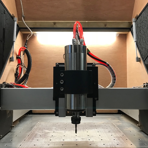
At this point you want to mount the spindle. On my spindle mount there are three holes in a vertical fashion. The middle hole is to thread an opening screw – to open the mount allowing the spindle to slide in. First step is insert this screw, open the mount slightly, slide the spindle in and then loosen the screw – the spindle should stay in place. Once mounted insert the other 2 screws and lightly tighten – the position/height doesn’t need to be perfect at this point.
Be careful as the tension on the springs might not be strong enough and the z axis might crash down.
From here it’s a matter of running cables and tubes to-from the spindle to where you place/mount your VFD.
I sliced my 5m of tube in half giving me two lengths of 2.5m pipe, and used the same amount of 1.5mm, 3 core wire.
The pipe is a simple push fit with a tightening screw around the pipe. The wire just needs to be soldered into the connectors. I would supply a wiring diagram but each VFD/spindle is different so I’d rely on the instructions provided. It is very straightforward and a matter of soldering the wires in place and clamping them in the connector.
Follow the instructions for your VFD to wire up your power supply and your spindle – typically you will have 2 power wires and 3 spindle wires – as earth is not used. The right connectors are for the spindle the left are the power input.
If during operation you get shocks off your machine or spindle you need to ground it using a 4th wire.
I got a little bit clever here, figuring every time I turn my VFD on I’m likely to want to power on the water pump and begin circulating the water system. To do this, I wired my pump to the VFD power input – if you turn on the VFD the pump comes on – it removes a switch and I can’t think of an instance where this would not be a suitable option.
For the water pump they will provide you with a submersible pump which goes inside a container. Due to mine going in my garage which is a dusty environment I put it inside a Tupperware container (approx. 4.2l) drilled 2 holes in the top (feed/return) and a space for the wire to slip out the side.
For coolant I used around 50ml of central heating protector and water + some food colouring. (So far so good). The pipe should be push fit on the water pump.
At this point you should have your VFD, spindle wiring, and water pump good to go. It’s now time to setup the automatic speed setup and stop/start of the spindle. Take the GND and PWM wires and connect them to your VDF as follows.
Connect the PWM pin to VI
Ground Pin to ACM
Short DCM to For with a short/low voltage wire.
Once connected you are ready to power on your VFD (this takes a couple of seconds to start up). There will be a number of settings that need to be changed based on your spindle – the supplier should advise the correct defaults but the additional changes need to be made. Change these whilst you machine is off.
Change setting PD001 in VFD to take external controls - to 1 – this allows for external speed control
Change PD070 to 1 - to accept a 5 volt and not 10 – changes the speed input to 5v (maximum S3 output via pwm)
Change $30 to 24000 in the GBRL setting – this states that at maximum output of 5v on PWM will be 24000rpm – as default this would be 10,000 or 12000 rpm.
Now these changes are made you can power on your machine and you should be able to start and stop the spindle using a computer. If you click ‘spindle on’ in CM it should run at approx. 1200 rpm. I advise creating a number of programs at various RPM to check the speed is correct.
When you are testing, ensure your spindle does not have it’s collet on and it is above the waste board. You will not be able to start/stop the spindle on unless the machine is on and it’s connected the the computer. Speed readings will be on the VFD and likely a few hundred rpm out. Calibration is possible using an external speed sensor.
You will now be at a point where you should check the angles of your spindle/mount and align then tighten the screws holding the mount.
Once you’ve tested your ready to go, so it’s time to dust off your new collets and get making.
Any questions pop them here and I’ll try to help.
Here is a useful video for setup.


 .
. I’ve updated above.