I bought a Shapeoko Pro XXL over the Black Friday sales and thought I would walk through my process of setting up the machine, building the enclosure, additional convenience addons, and my initial carvings with lessons learned. This community has been extremely helpful with the extensive history of topics and I thought I would compile all the resources that I used to guide my process to make it easier for others to find solutions and give some ideas as well. There is a supply list of the main things that I used at the end of this post as well as links to other Carbide 3D posts that helped me.
Grab some popcorn as this will be a long read.
To give some initial insight into this build, my objective is to start a business selling things online and at craft shows in my local area. I also like to go the extra mile which you might see and try more new things just because I love to experiment and have an arsenal of ideas in my pocket.
“Final” Build Pictures (There are still some things I am wanting to add):


*I am terrible at remembering to take progress pictures so they will skip sections although if there are questions on something let me know.
Part 1 - The Shapeoko Pro XXL Build:
Location of build: I am building this on an upper balcony in my parents shed where there was some room that wouldn’t take up main floor space. The only two downsides to this so far is that I have to walk down to the main floor to grab things that I need quite often and the ceiling height is about 5’9” and I am a little over 6’ so I have to crouch when walking around.
There were a lot of boxes, but I have to admit that the flow of setting the machine up was pretty fluid by just following the provided build manual that came in the main box. It took me a few nights after work to set the machine up.
1st Night:
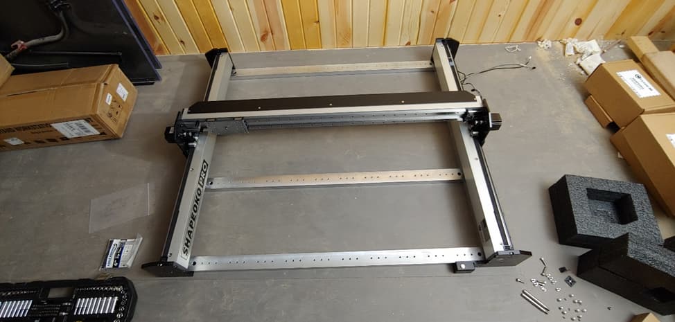
- Pretty straight forward, just mechanical fasteners for the most part. Installing the belts probably took the longest to get the same tension on both rails.
2nd Night:
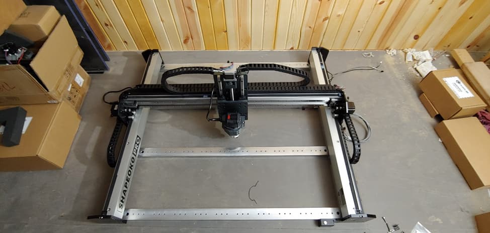
- This part of the build took a while for two reasons. Getting all the cables routed takes time, nothing challenging, just time consuming. The second reason is because I bought the HDZ and had to take parts off the other x/z assembly and get everything installed on the new HDZ. I didn’t follow any instructions for installing the HDZ as I could see what I needed to change in order to make it work like the original x/z assembly.
The reason I went with the HDZ is because I had a gut feeling that I would want to upgrade to a spindle sooner rather than later and it was on sale.
3rd Night:
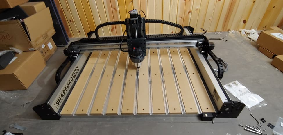
- The spoil board installation was easy as one would expect although there were a lot of screws to install. I don’t have it pictured here but I also installed the controller on the side of the machine and hooked that up as well. No test run yet at this point.
Part 2 – The Enclosure
Fast forward since I didn’t remember to take any pictures.
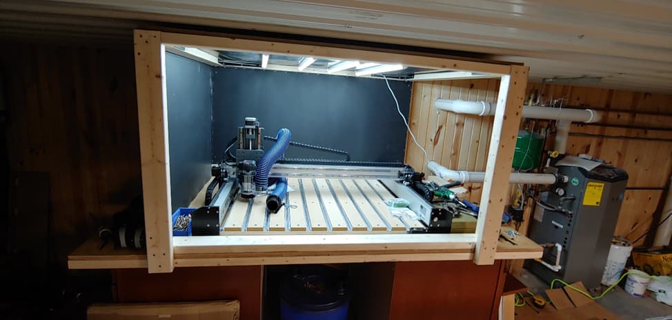
A lot happened here so let me walk through everything. For starters, I needed something I could set the machine on. I didn’t need anything with rollers as this has nowhere to go without disassembly. I could have built a nice bench to set it on, but the cost of lumber right now is rather high and if a few years down the road I want to move it, I would have to disassemble the entire thing to get it down from the balcony anyways. I chose to go with two 36”W x 24”D x 34 ½”H cabinets from our local home improvement store – Menards as I could easily reuse/repurpose these cabinets down the road.

On top of the cabinets is a ¾” sheet of construction plywood that was lying around and was pretty flat. The total size of the top is 4’x7’ so there is about a 9” overhang on the back and a 3” overhang on the front. I reinforced the front and back bottom edges with a 2x4 the entire length to add rigidity and a place to screw into. The enclosure frame is also made entirely of 2x4s as I once again was planning on disassembling this in the future since if/when I rebuild it, I am sure I will make something a little nicer.
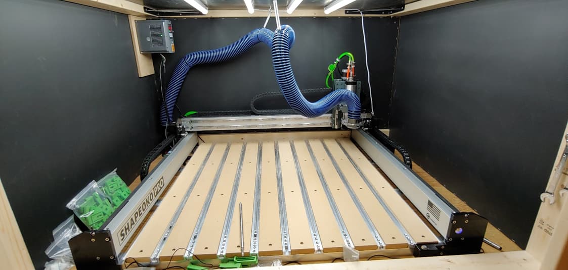
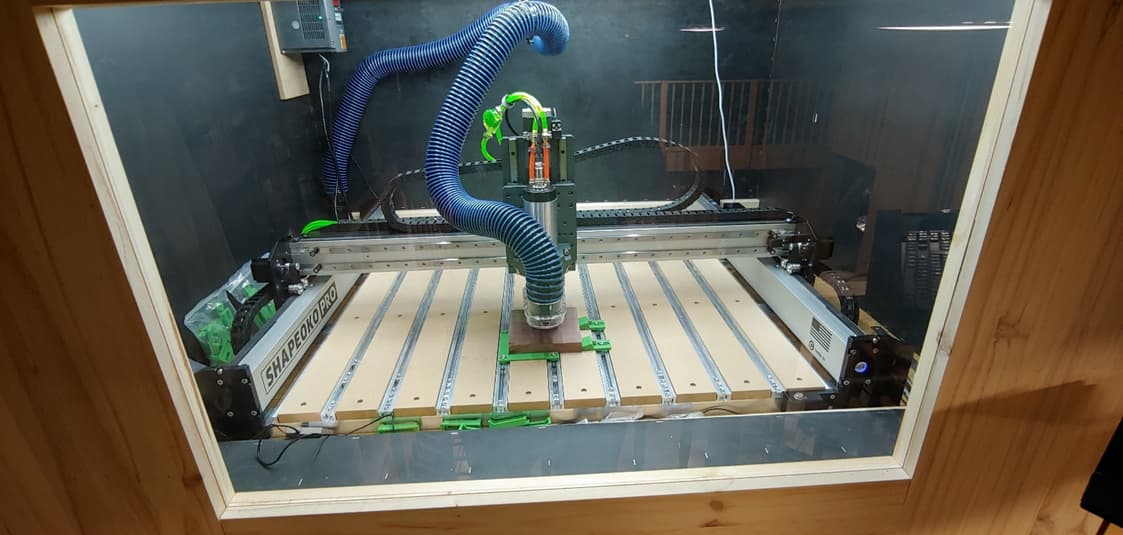
The side walls and ceiling of the enclosure are ½” MDF panels with black 1lb mass loaded vinyl (MLV) for the sound dampening which is the black inside walls. I used a staple gun to tac the MLV onto the MDF and then installed the pieces onto the 2x4 frame. After browsing various enclosure designs, I went with MLV since it looked like it would do the job well and I wanted to try it out just to keep the idea of a good sound dampening material in my arsenal. The dimensions of the inside of the enclosure are 60”W x 43”D x 33”H. It is big enough inside where I can sit and work on something if needed.
I wanted the machine to be well lit, so I perused on Amazon for something that looked like it would do what I wanted it to. The lights are strung in series and were fixed onto the ceiling with as wide of spacing as the kit would allow (about 7”) without me soldering additional length to spread them out farther.
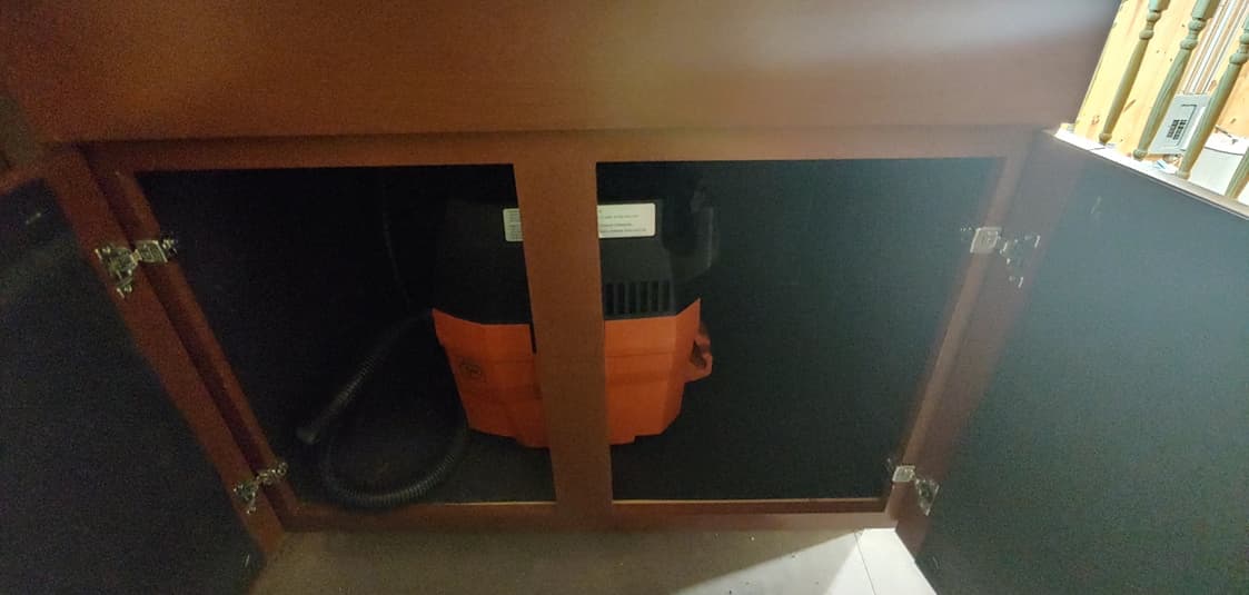
Some other things to note before the next time skip. The shopvac that I am using is sitting in the left cabinet that has MLV around the entire interior. I still need to route an air inlet hose that brings in fresh air to the shop-vac as I need to leave the door open on it currently which defeats the purpose of the MLV. The blue hose dust hose is a 10’ anti-static hose that I bought from Rockler. I should have bought 2 as I ended up going to Menards and picking up a 7’ extension kit which was fine as it came with adapters that I could hook into the smaller hose that came with the Fein Turbo. As for powering everything, I have a power strip underneath the plywood in the back the I have most of my power connected to.
Part 3 – The Spindle and VFD
On to the next time skip:
A lot has happened again from the previous portion. As you can see, I now have a spindle and VFD hooked up. The moment I turned the Carbide compact router on I knew I wanted something quieter and so the quest for finding a spindle and VFD began. There is a list of references that I used at the bottom of this post to help guide my decision and how to assemble it. I ended up getting a 65mm spindle and VFD kit off amazon as I preferred to keep the dust collection system the same. I also chose 110 V as I didn’t want to run 220V wire up to where the machine is at.
Hooking it up wasn’t too bad as the reference posts helped tremendously. Basically, I had to unscrew the female connector on the spindle and add a ground wire that was missing. There was no easy place to connect it to the body of the spindle so I ground some paint around the connector opening on the body to expose metal and then sandwiched the wire between the body and connector when I screwed the female connector back to the housing. After that I wired the aviator connector up using some 4 core wire I bought off Amazon. It is only 18 gauge and not shielded so if I had to do that again I would go with 16 gauge and shielded wire. The 16’ length of wire was just enough to also leave a few feet extra that I then coiled up and hid out of the way. Wiring into the VFD was pretty simple following this post.
I had a cut off extension cord that I used to wire up the power to the VFD and the only thing left to do was wire the ground and PWM signals to the Shapeoko control board. For that I ended up using stereo wire and a dupont connector that I had laying around from a previous PC build.
Now that the power was ran to the VFD I needed to run tubing to cool the spindle. The default tubing that it came with was not long enough and not flexible enough to go inside the wire channels. The problem here was that the tubing connectors on the VDM were metric and any tubing I could find quickly at local hardware stores were imperial. I ended up getting ¼” ID tubing and some barbed fittings that I could make work. In the picture above the orange tubing is what was supplied with the spindle so I used the fittings and some hose clamps to make sure the transition would not leak. I also hooked in a flow indicator so I could easily tell the pump was working.

For the pump I used a 5 gallon bucket and lid which I drilled two holes for the hoses and 1 larger hole that I could run the power cable through. I used two gallons of automotive coolant that were concentrated so I diluted it with water to become a 50/50 mix that totaled 4 gallons. It is probably overkill for keeping the spindle cool, but I also ordered a temp sensor I could stick in there to see what temp readings I am getting after it has been running a while.
I finally was able to run the VFD and Boy-O-Boy is that noise improvement astronomical. It was a night and day improvement for sound quality. The only thing that bugged me was the fan on the VFD was louder than the spindle and thanks to some great ideas on this forum I bought a 40C thermistor that I attached to the heatsink inside the VFD and wired into the fan so it will only turn on when temps inside the VFD exceed 104F. Now the spindle and system is extremely quiet. Note: Make sure to check the direction the spindle is spinning with some tape and typing M3SXXXX into the MDI screen on Carbide Motion where XXXX is a value. I used 60 so I could easily see it spin.
I also bought some ER11 Collets that will work with the bits that I have.
Part 4 – Electronics
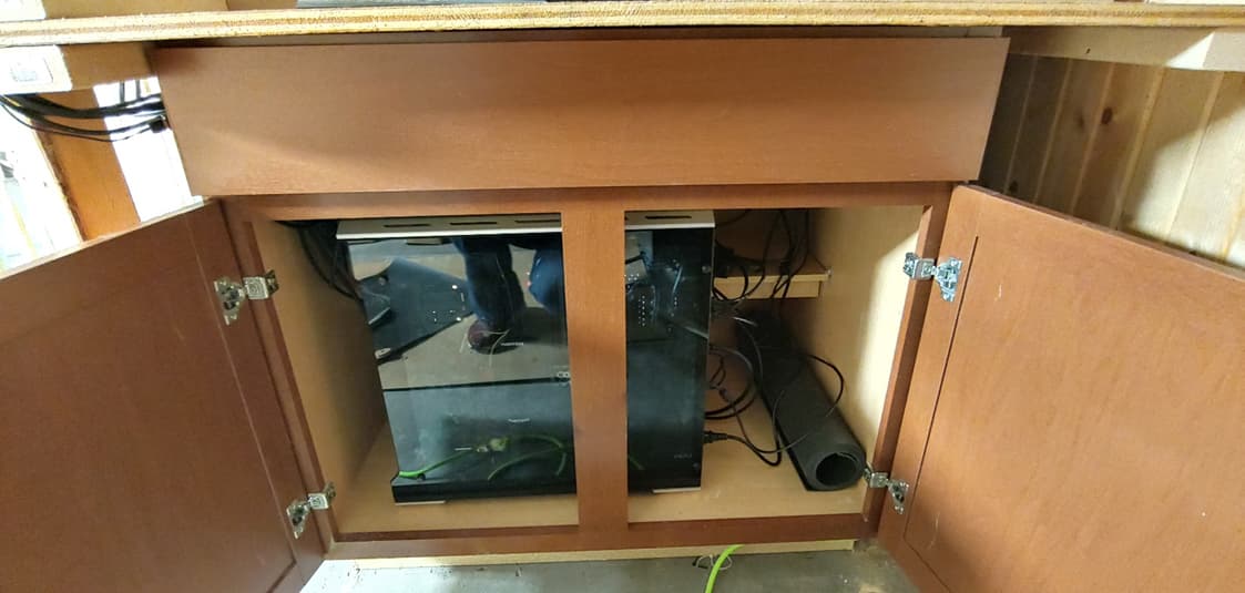
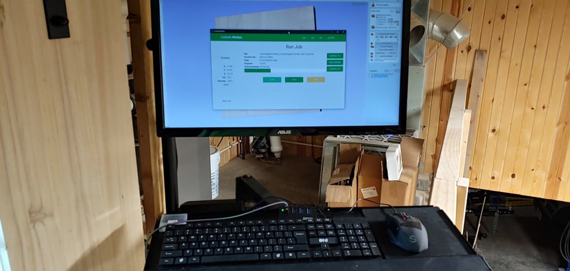
On to the electronic side of things. I had a spare computer from a previous PC build that I hadn’t used for a couple years which is what I have the machine hooked into. This is sitting in the right cabinet and has a rat’s nest of wiring running through it. I wanted to be able to create designs while sitting next to the machine so this setup works out well. The monitor and mouse were spares that I had laying around. I bought the monitor and keyboard mount off amazon as I wanted something that was convenient to use.
I ended up getting Vetric’s vcarve pro software which while it is expensive I find it will suit my creativity and complexity of designs and I will probably end up getting Aspire once I have the current software mastered.
Believe it or not I still had not actually run any programs on the machine to see if it works outside of initialization. I knew if I started running things, I wouldn’t finish some of the objectives that I wanted to accomplish because I would be preoccupied.
Part 5 – Finishing Touches
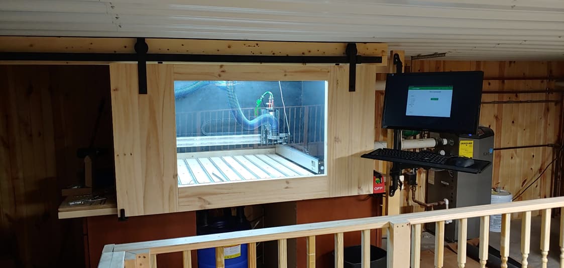
The next step was getting a door created. After some design considerations I opted for a barn door style opening. This would allow me full access to the front without having doors or pneumatic openings to deal with in the limited area in front of the machine. I had to find 10’ barn door hardware as my door would need to be just shy of 5’. I found the hardware on Amazon (The 10’ one that I bought appears to be removed but I have linked to the same seller of smaller sizes) and needed to add a roller to the bottom left to keep the door from swaying. The door/window was made out of edge glued pine from Menards and some window glass. I cut a ½” deep dado on the inside of each of the four pieces where the glass can slide into place. The 4 pieces are held together by pocket screws – normally this wouldn’t be my ideal design choice, but I wanted an easy way to replace the glass if it broke.
The finish line was in sight now but there were a couple more additions that I wanted to add before I ran some programs. First was the E-Stop button mounted on the right hand side. This was more of a plug and play E-Stop switch as I didn’t feel wiring in something in place since I don’t have a control panel. I chose not to go with a control panel for simplicity reasons and I think what I have works for me. I have an automatic control switch set up so when I press the power button on the machine the ceiling lights, VFD and pump all turn on. When I press the switch again there is a 7 second delay before everything turns off.
That is everything that I can think of that went into this build.
Future additions or things I am waiting to receive:
- Bitrunner – I had already ordered this and it is currently being shipped to me. I am going to have this run my shopvac so it turns on and off depending on the PWM signal from the controller.
- Smoke Detector – I wanted something that I could hear if I was in a different area of the shop.
- I am looking to make something to hold the work holding pieces as well as all the bits that I have.
Part 6 – Running the Machine
This is the process that I use although I just started so take it with a grain of salt.
- Turn the machine on
- Initialize the machine
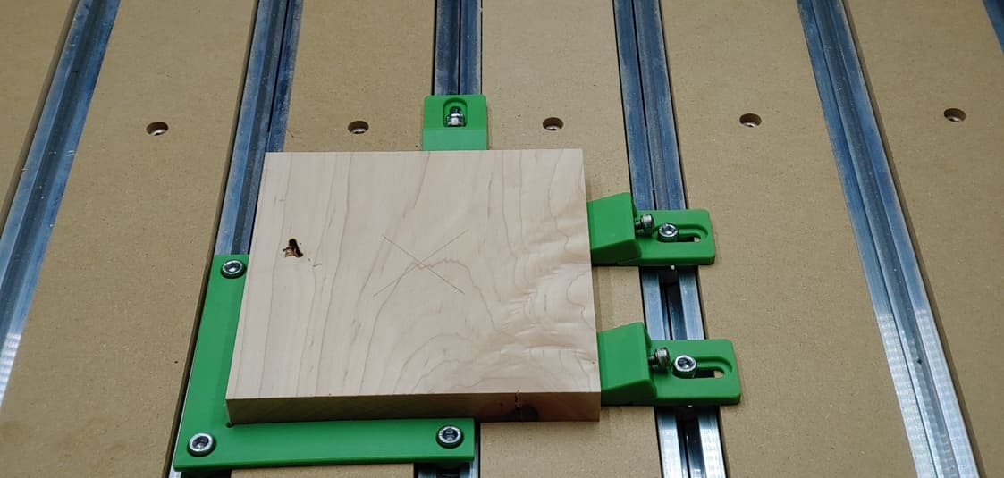
- Mark the surface of material (I have been basing my x and y on the center for these)
- Install the bit I want to use for the program that I am going to run
- Zero the x any y when it is centered over my part
- Run the probe with BitZero to get material height.
- Run the program – I have each program split out for different bits – so my roughing pass is a separate program from the finishing pass.
- Once it finishes, I run the next program. I install the bit I am going to use and it remembers where zero is for all axes.
I decided to go big or go home with my first design and I definitely went home…
The goal was to create an inlay of the below heart and tree – I used the 1/8 flat up cut bit for the roughing passe on the male insert and the ½” 60 degree v bit for the detail on both the male and female parts of the inlay.

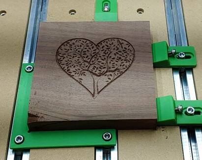
Overall, the female part of the inlay looked okay. I think the bit had trouble with some of the smaller branch details as they were not visibly cut which isn’t what I wanted. Now, onto the Male part of the insert to see how that turns out…
Right when the program started running it was extremely loud and burning the wood. This is when I remembered I never checked the direction of the spindle and was kicking myself for it. The spindle was spinning in reverse and I was amazed that the 60 degree V bit cut fine on the female portion (it was probably because the bit does have sharp edges on the back side of the cutter). To remedy this, I just had to switch two of the power cables that were feeding the spindle in the VFD.
After that fiasco I reran the program and it definitely did not turn out as detailed as I was hoping. The maple was chipping on some of the finer details which made it unusable. I am hoping a smaller v bit will solve my issues with the chipping and lack of details.
I then moved on to something that had less detail to see if that would work better.
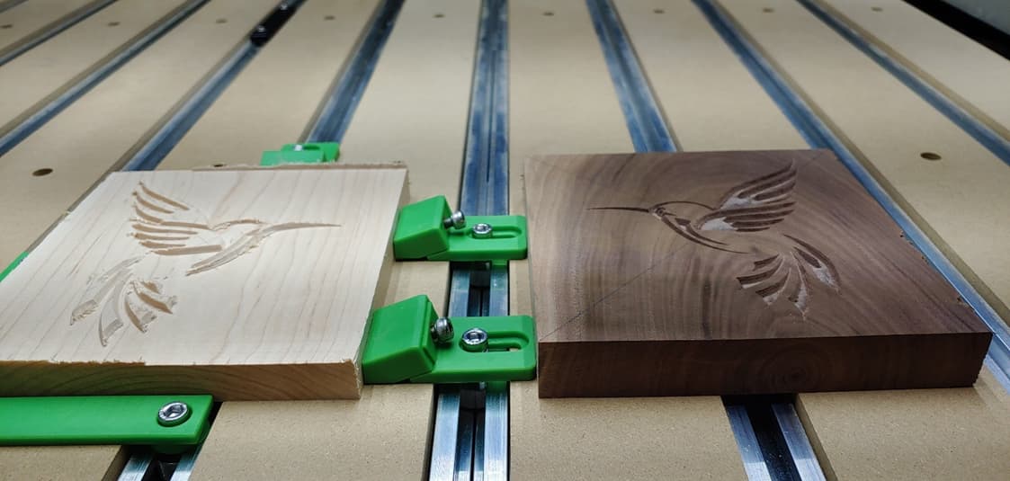
These turned out a lot better but there was still some chipping on the finer details. I still glued these up to see how it would turn out. I was impatient and only waited about 4 hours before I did the cleanup on the router which caused some chip out on the upper wings but overall, I could see the fit was perfect.
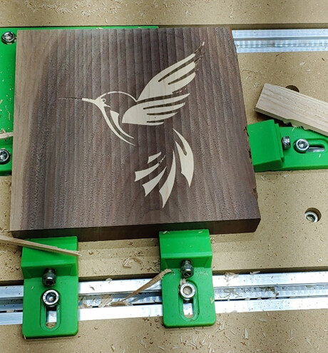
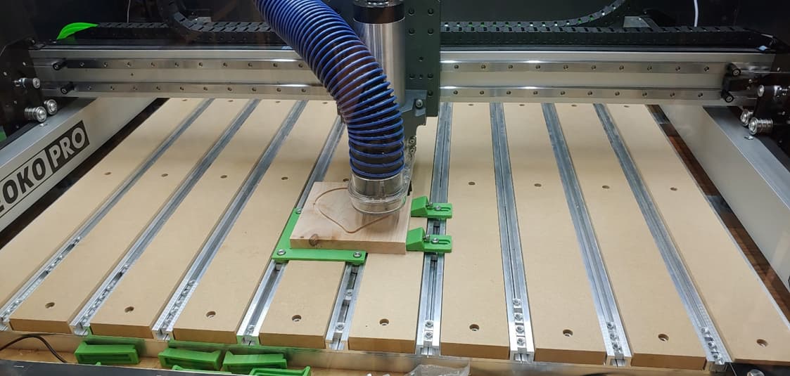
I wanted to then debunk whether it was the larger bit or not so I used some 1/8” 10 Degree engraving bits that came with the spindle and tested it on the hummingbird again. The results for the cuts looked a lot better although it took more than 2 times as long to cut it out. I accidently ran the wrong program initially on the walnut piece which is why there is a groove around the bottom and right edge (lesson learned for creating a better file naming convention).
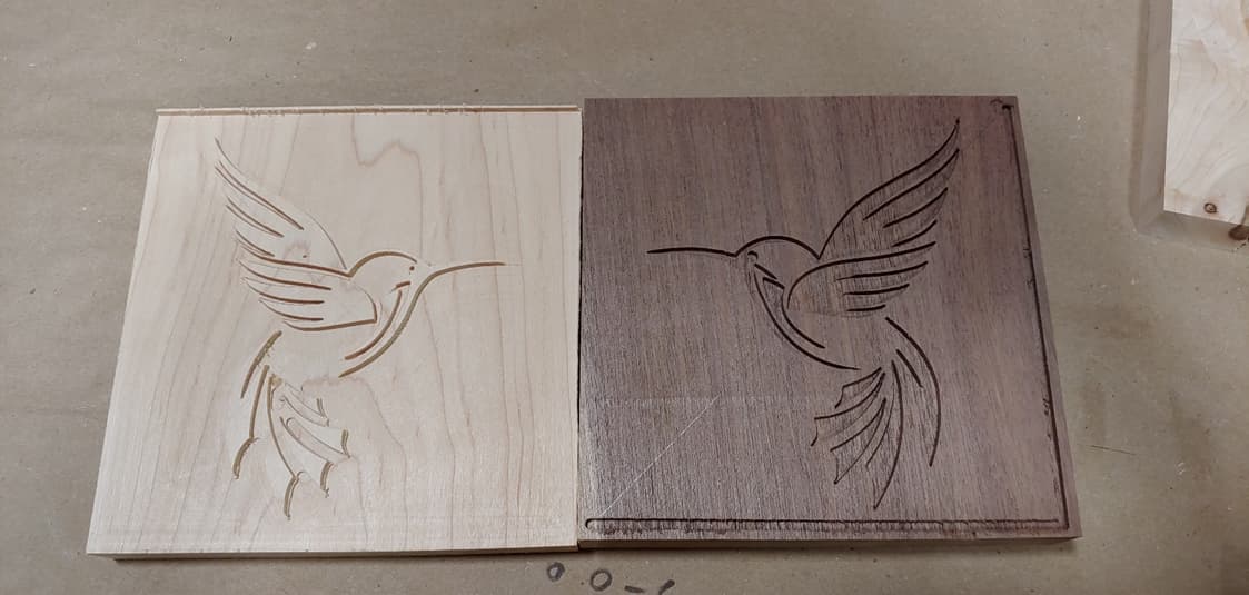
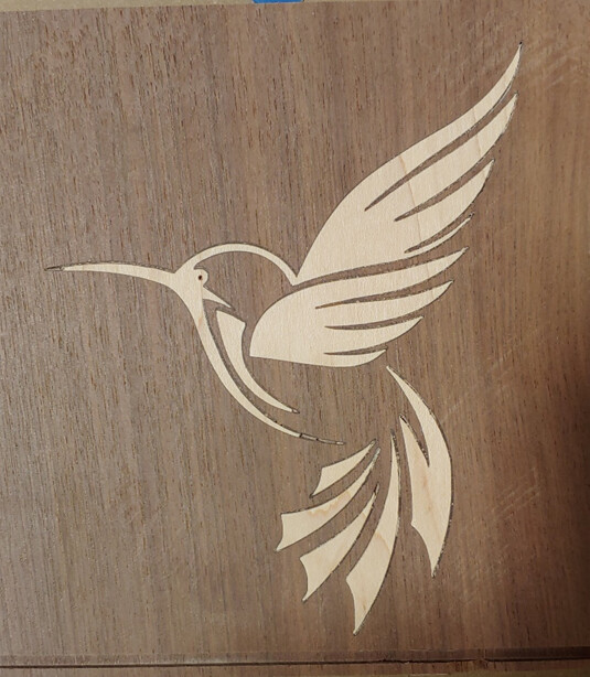
It still isn’t good enough, so I am open to some suggestions on making this work better.
That is where I am at on my journey with the Shapeoko Pro XXL.
I also have a couple of questions for this community;
- What is the best lubricant for the x and z rail as well as the ball screw on the HDZ?
- Is there any way to add a delay at the beginning of all gcode files that are created that gets the spindle up to speed because as of right now it doesn’t get to the rpms it needs to before it plunges in the wood? Anything setting in VCarve that allows this option?
I would like to thank this community again for all the great content and forum as it makes solving problems and coming up with ideas easier.
Supply list:
Cabinets – Qty 2
8ft 2x4 – Qty 5
MLV – Qty 1
Ceiling Lights – Qty 1
Fein Turbo I Shop Vacuum (Rockler) – Qty 1
Anti-Static Dust Hose 10ft (Rockler) – Qty 1
Dust Right® Dust Separator (Rockler) – Qty 1
7’ Hose extension and adapters – Qty 1
Power Strip – Qty 1
Spindle and VFD kit – Qty 1
4 Core Wire – Qty 1
Thermistor for VFD fan – Qty 1
10’ VFD coolant tubing – Qty 3
Hose fittings – Qty 4
Flow indicator – Qty 1
Fluid temp sensor – Qty 1
Keyboard – Qty 1
Monitor and Keyboard arm – Qty 1
10’ Barn door Hardware – Qty 1
Barn door roller – Qty 1
5/4 Edge Glued Pine – Qty 2
4/4 Edge Glued Pine – Qty 2
Window glass – Qty 1
E-Stop – Qty 1
Automatic Control Switch – Qty 1
Smoke Detector – Qty 1
ER 11 Collets – Qty 1
VCarve Pro – Qty 1
Carbide 3D reference posts:
SO3: XXL Mega-Enclosure and Dust Collection
What do you think about my enclosure design for the pro XL?
Instructions for fitting a 2.2kw (or other power spindle) and VFD
VFD Parameters (Huanyang model)
Carbide Motion PCB v3.0b pinout


