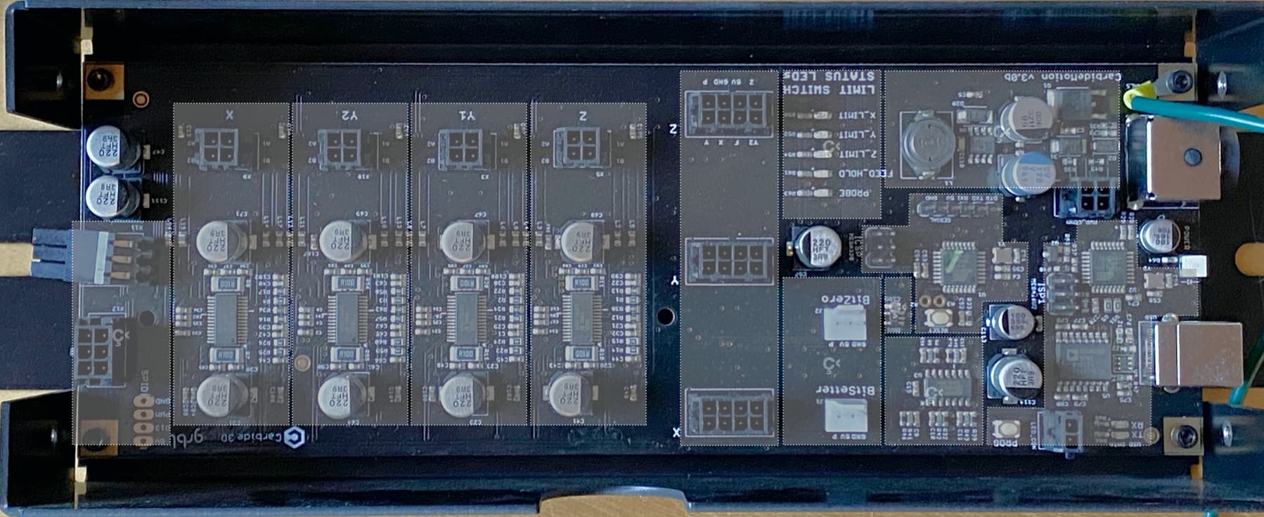
I’m struggling to find documentation for the Carbide Motion v3.0b controller PCB that came with my machine. I’m interested in how the Bitsetter, BitZero, as well as the auxiliary external connector are connected to the micro controller.
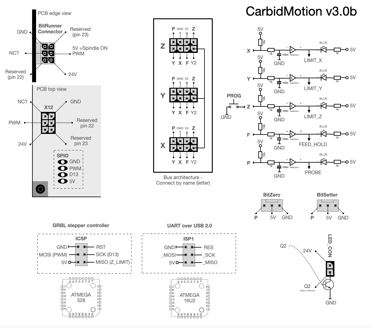
With it being kind of awkward to measure on a board that’s still installed in the machine, I’ve only been able to identify the Bitsetter connector, which seems to have the DC power supply ground on the rightmost (as installed in the enclosure) pin, +5V on the center pin, and A5 on the leftmost pin which needs to be pulled to ground to trigger the probe.
Is any documentation available on this, or have any of you perhaps already gone out of their way to identify the pinouts of the other connectors?
I don’t think there is (or will be) an official/supported documentation, but search for @Norway posts, he has done some of the “reverse engineering” work in this post that you may find useful:
Some of my notes. I think this is the degree of what I can assist with without being kicked out of the forum. I reckon that C3D support is careful not to give too much advice regarding warranty liability… “Y2” is interconnected in the X, Y, Z connectors, but else unused? “LIMIT_?” signals goes directly to CPU. BitZero and BitSetter has the exact same signals.
A tip for an emergency stop if the grounding clip from the BitZero has fallen off during probing - press BitSetter
I wouldn’t worry about being kicked off - I’m sure people have seen schematics of an Arduino Uno with some stepper drivers and Schmitt inputs before.
In your schematic, are the inverters intentional? I thought U3 was non-inverting, and your schematic makes it seem like all the LEDs would be illuminated unless the input signal is pulled low against the associated pull-up resistors.
Any idea what the 6 pin connector that I would need to use for a cable on the bitrunner is called? I ordered a few 6 pin molex things on amazon and none were right.
You are right @rafl, my fault. 74HC7014D is a Hex non-inverting precision Schmitt-trigger. I updated the schematic published earlier rather than posting a new one as these things gets copied and forwarded.
Did you measure one of the capacitors in the RC filter out of circuit to find their value? As shown it seems to have a 1.6kHz cutoff frequency, which I thought was surprisingly high.
Can’t remember, but I probably did since my notes say 100n and the resistance is 1k. I have a multimeter that can do that measurement. The Schmitt trigger will reduce debounce and at the same time be a protection circuit for ATmega 328 and a driver for the status LED. End stops only need to trigger once to define the edge, but with a quick response to achieve the desired precision I guess.
I’ve wondered about these frequencies too, but I’ve seen much higher in other controllers. I guess it comes down to the trade-off between frequency cutoff and response time, but do you know if there is an ideal cutoff frequency? @rafl How low do you think it should be?

 Late night work
  Fixed it