Insulating scales for a micrometer

Background:

I have a problem. I like measuring tools. I am not (quite) a collector, as most of those that I acquire are for use, either in the shop or in one of my field kits, but when I see an orphan at a good price and in usable shape, it tends to follow me home.

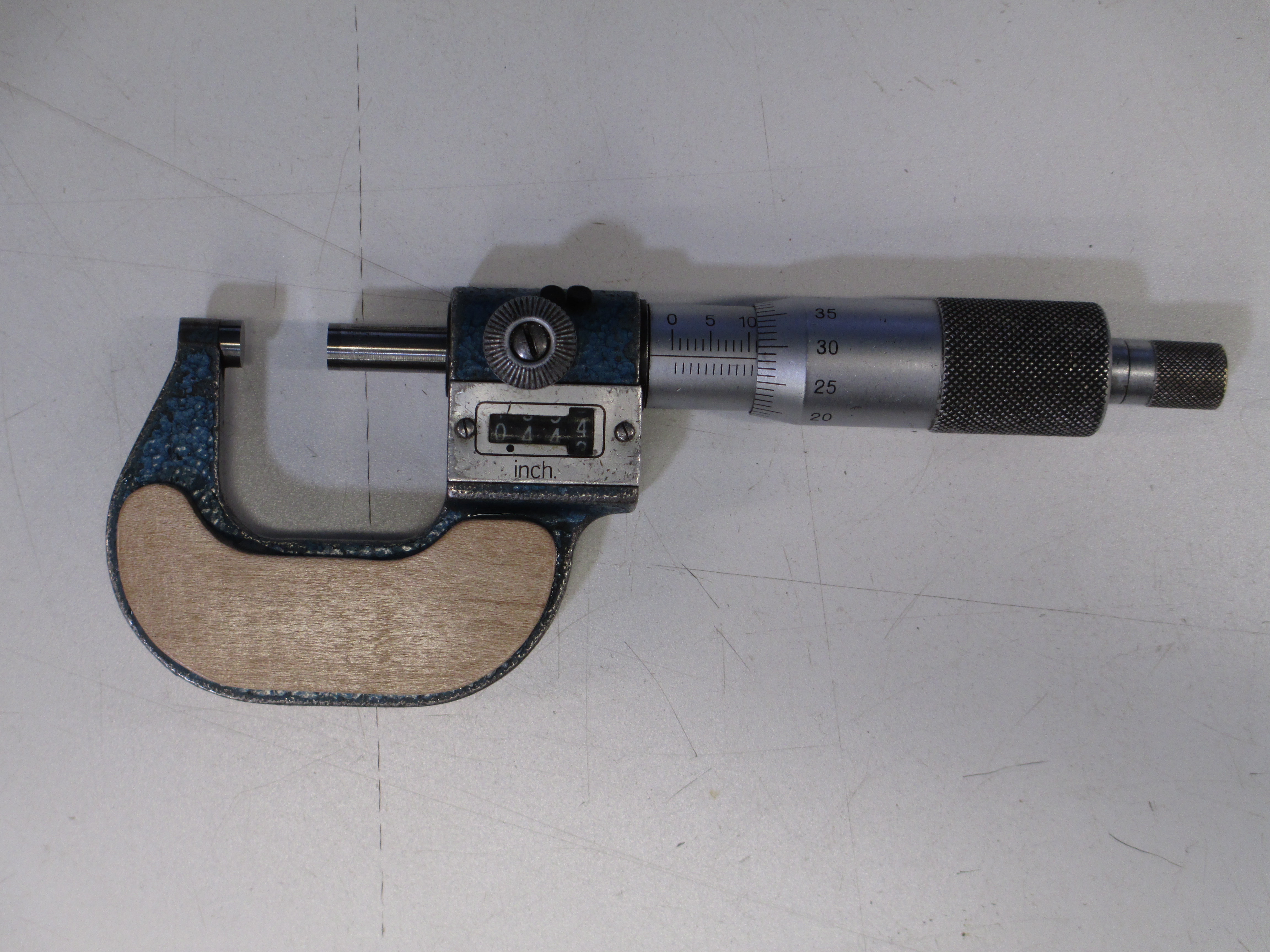
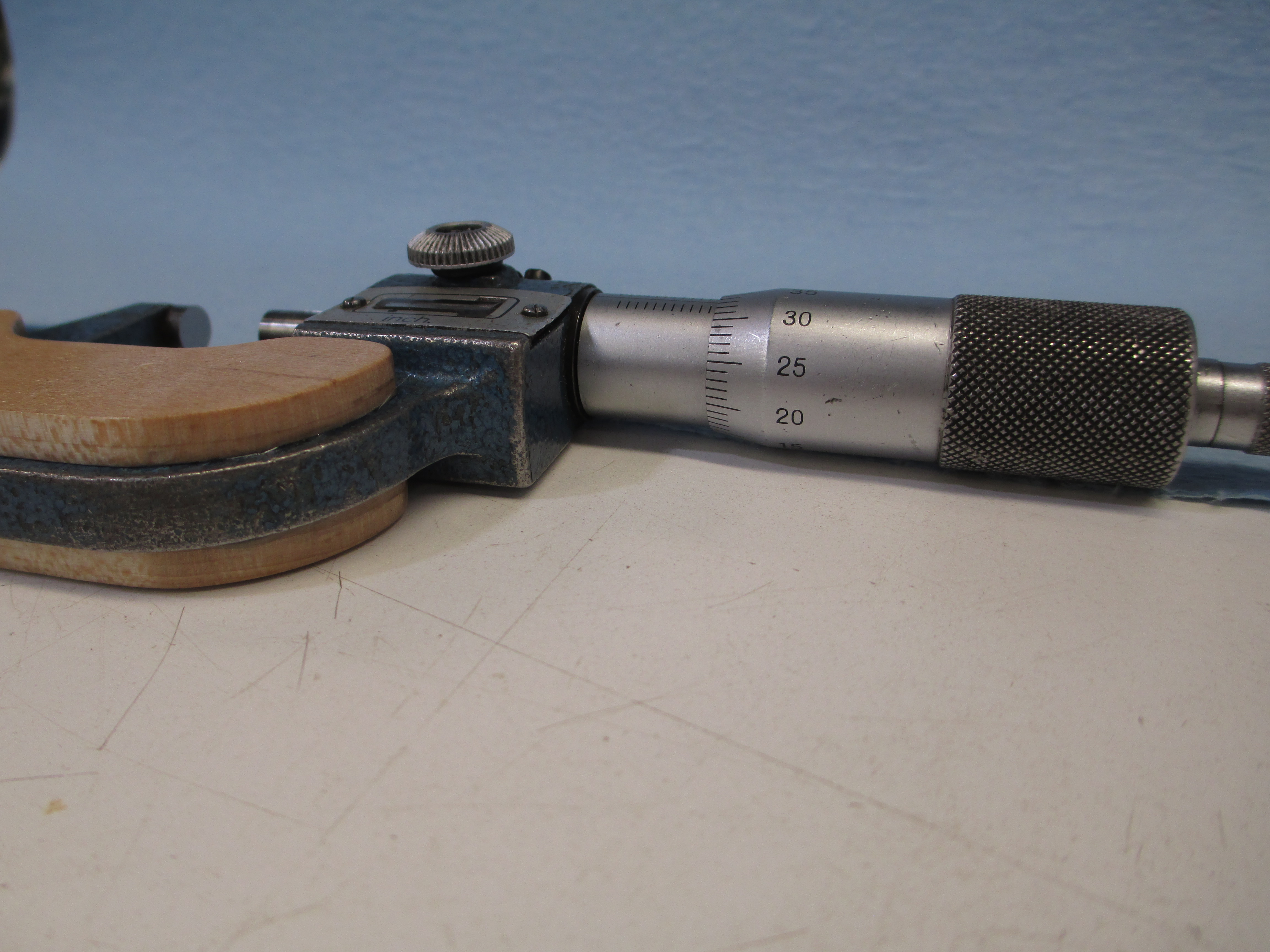
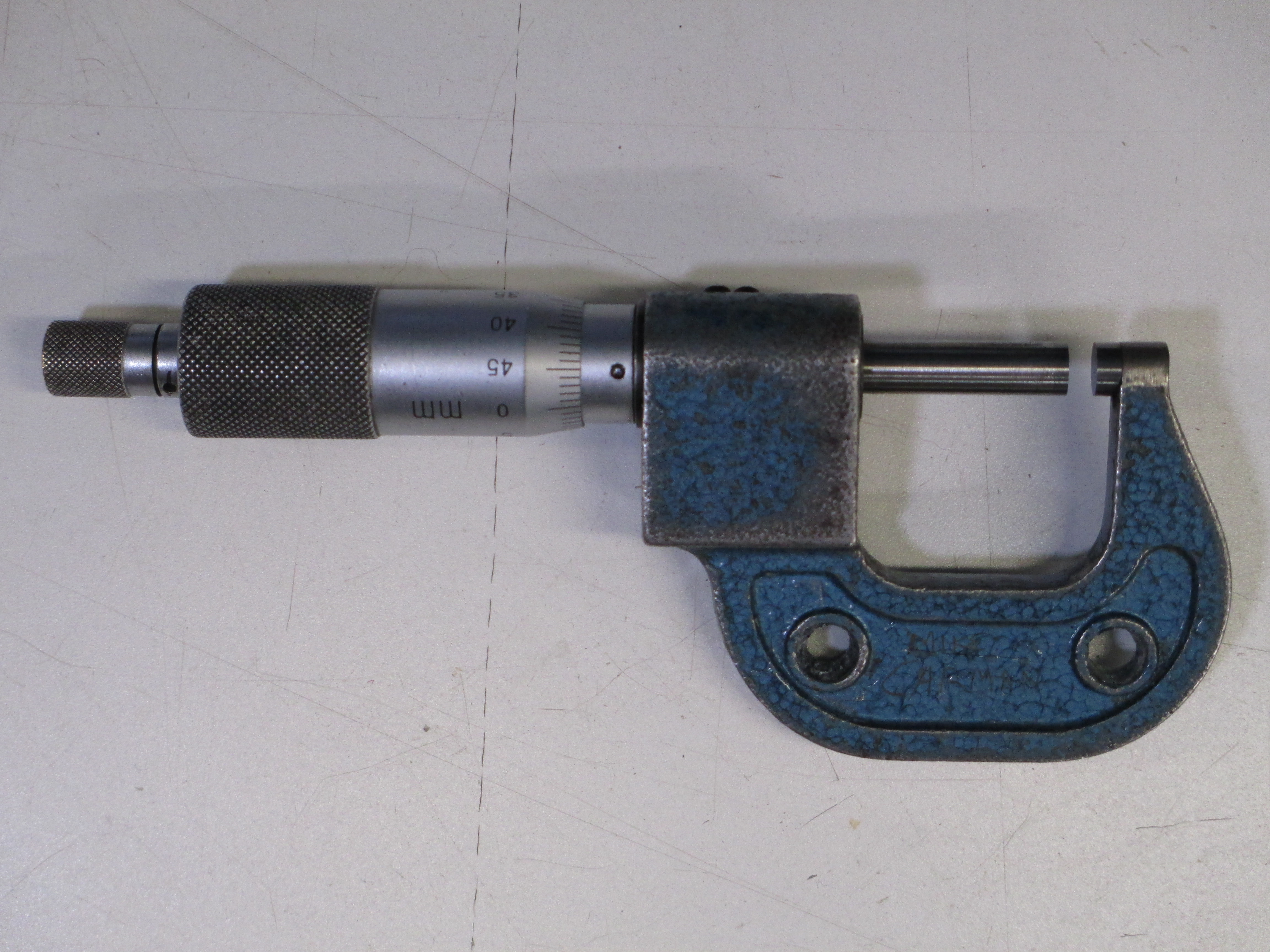
In this case, the orphan is a Mitutoyo Combimike 159-101, a metric and imperial mechanical micrometer, with metric read on the barrel and thimble to 0.01mm, and imperial on the mechanical counter, to 0.001" (a real neat design, as the groove for the mechanical counter is at a slight helix to compensate for the gear ration not being exact for the metric to imperial conversion)

It has seen some use and not a lot of love. The insulating scales on the frame were long enough gone that a previous owner had engraved his name in the frame. The paint is worn and chipped. It was way out of calibration-- the thimble zeroed at -0.15mm and the counter at +0.020", approximately.

After the repairs and calibration were done and the tool checked over the full range(not for this forum), it was time to improve the appearance from

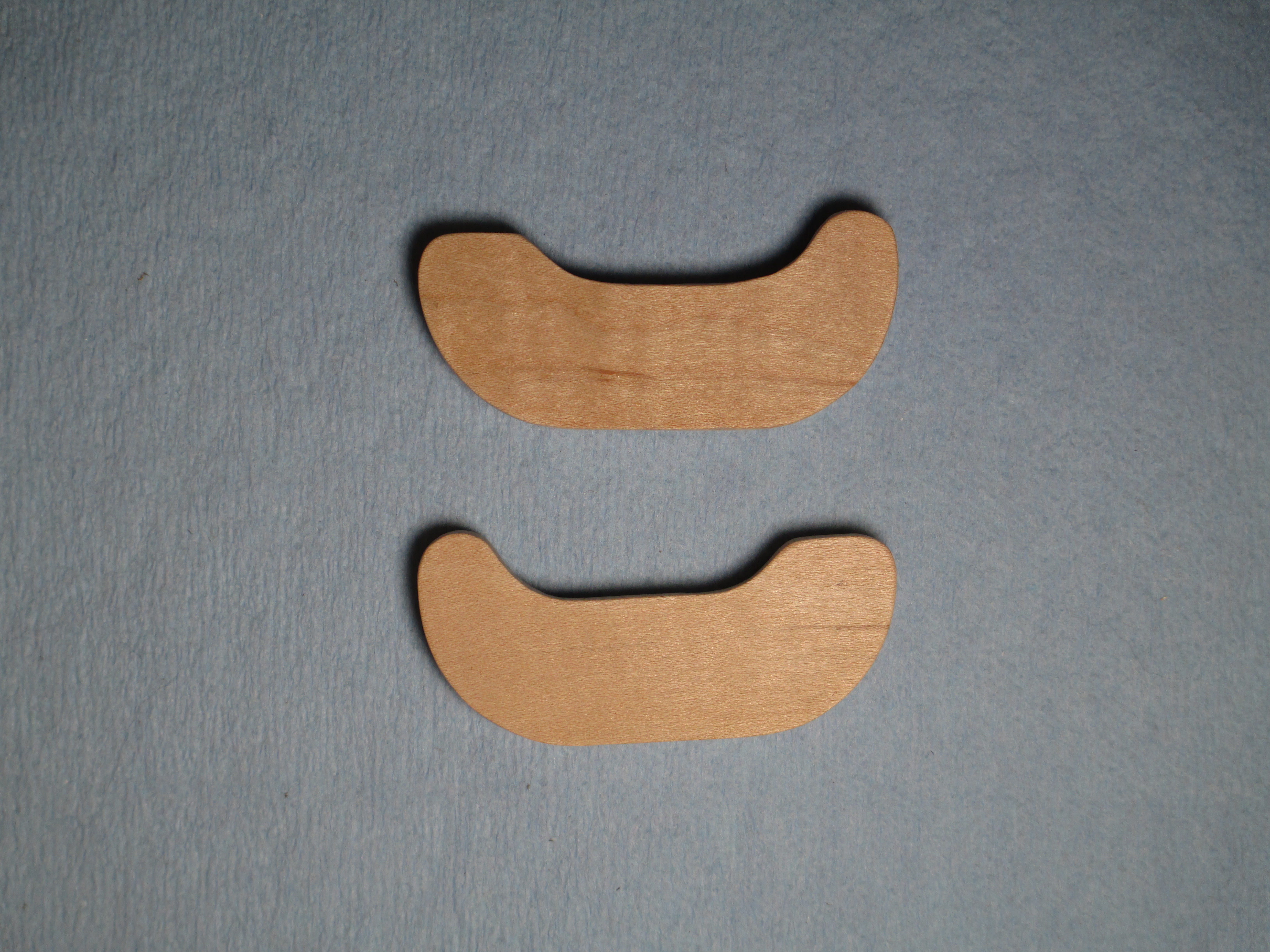
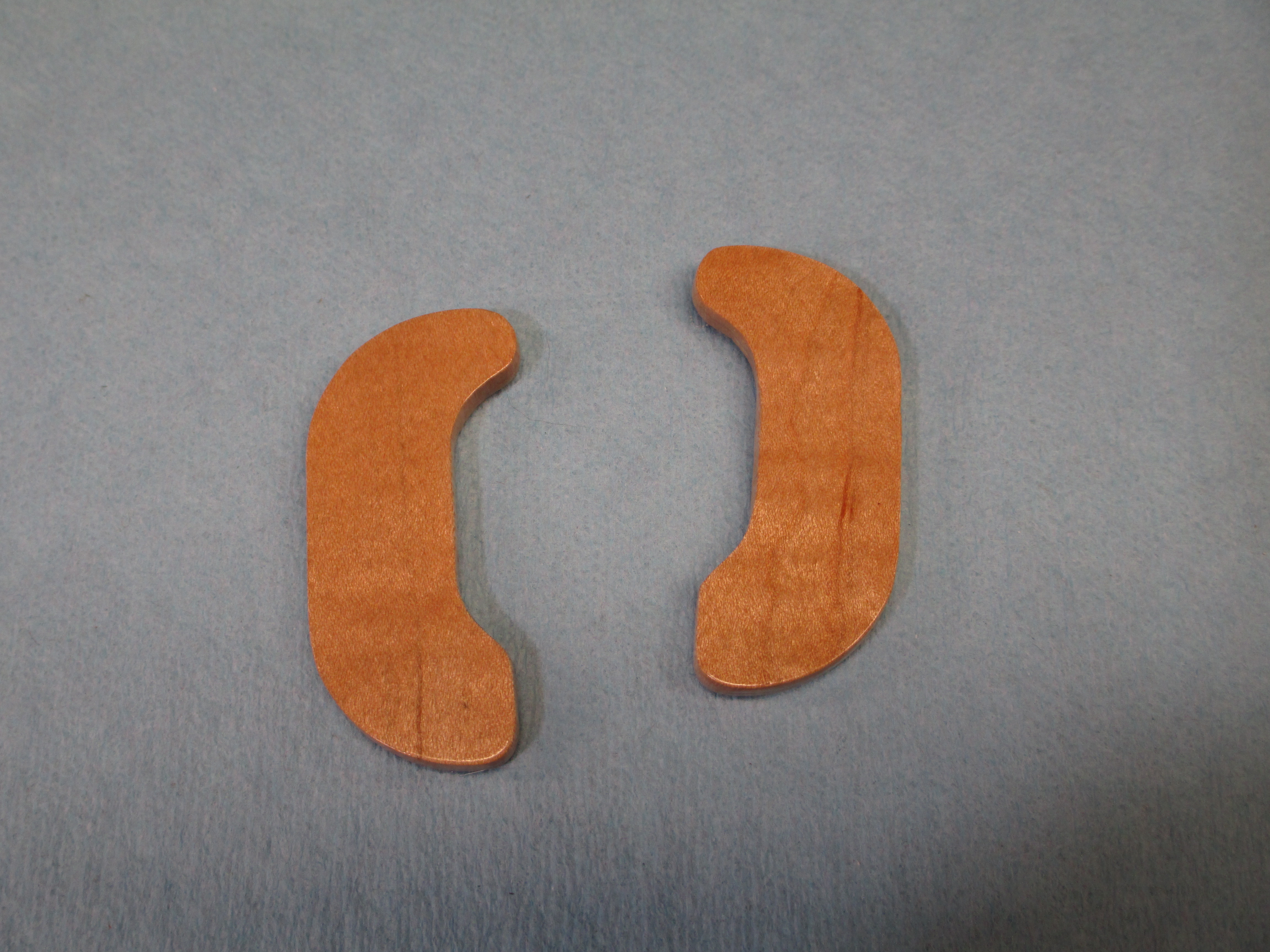
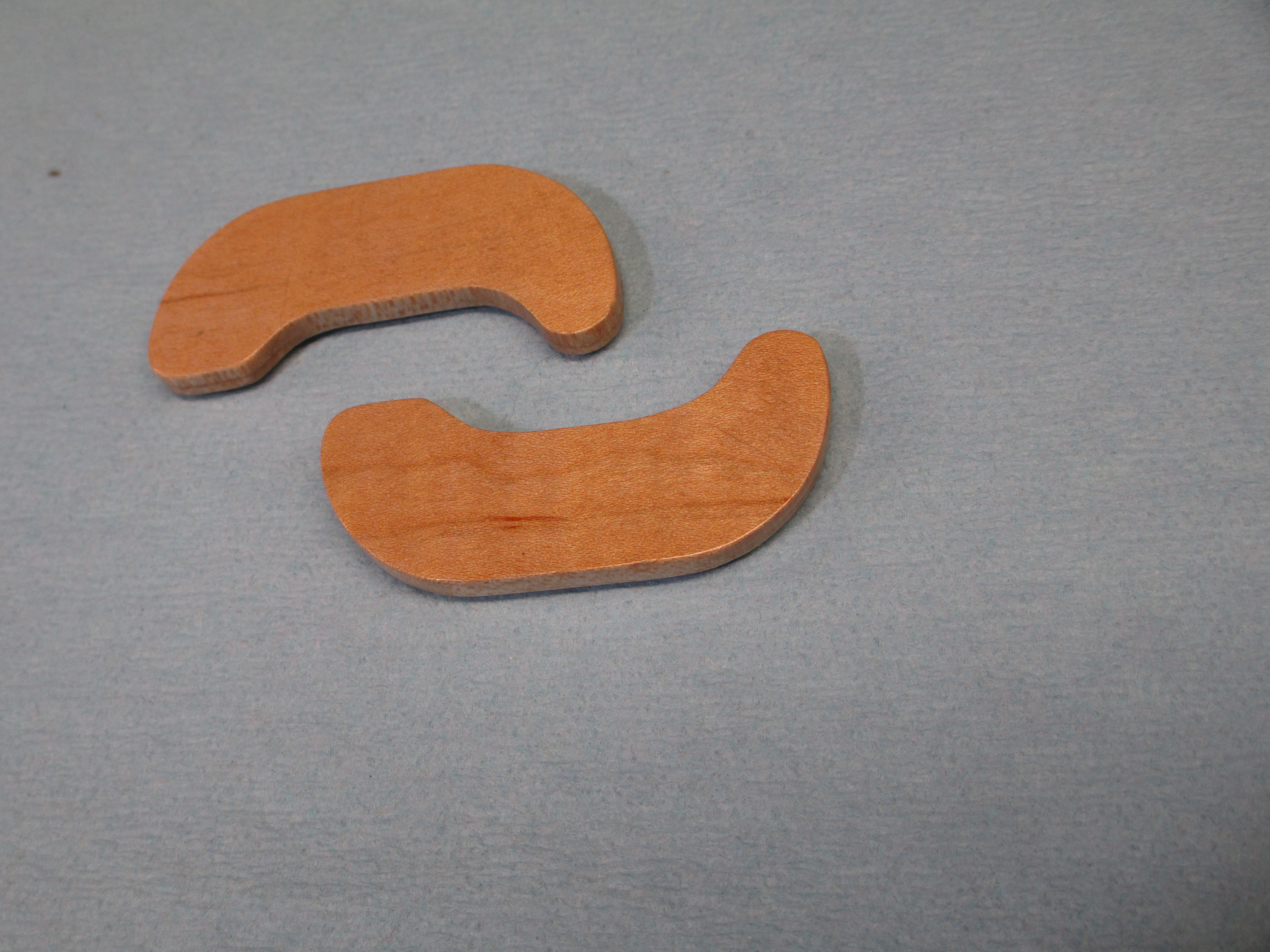
The wood I chose is another piece of my friends maple tree, with really nice grain. Absolutely lovely wood.

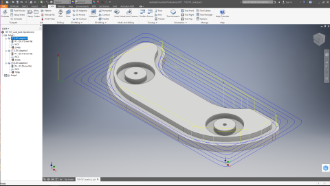
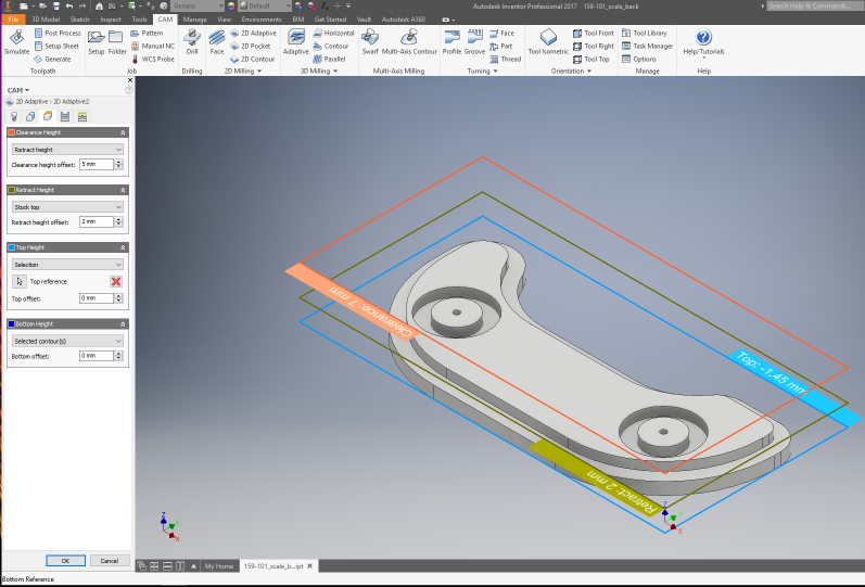
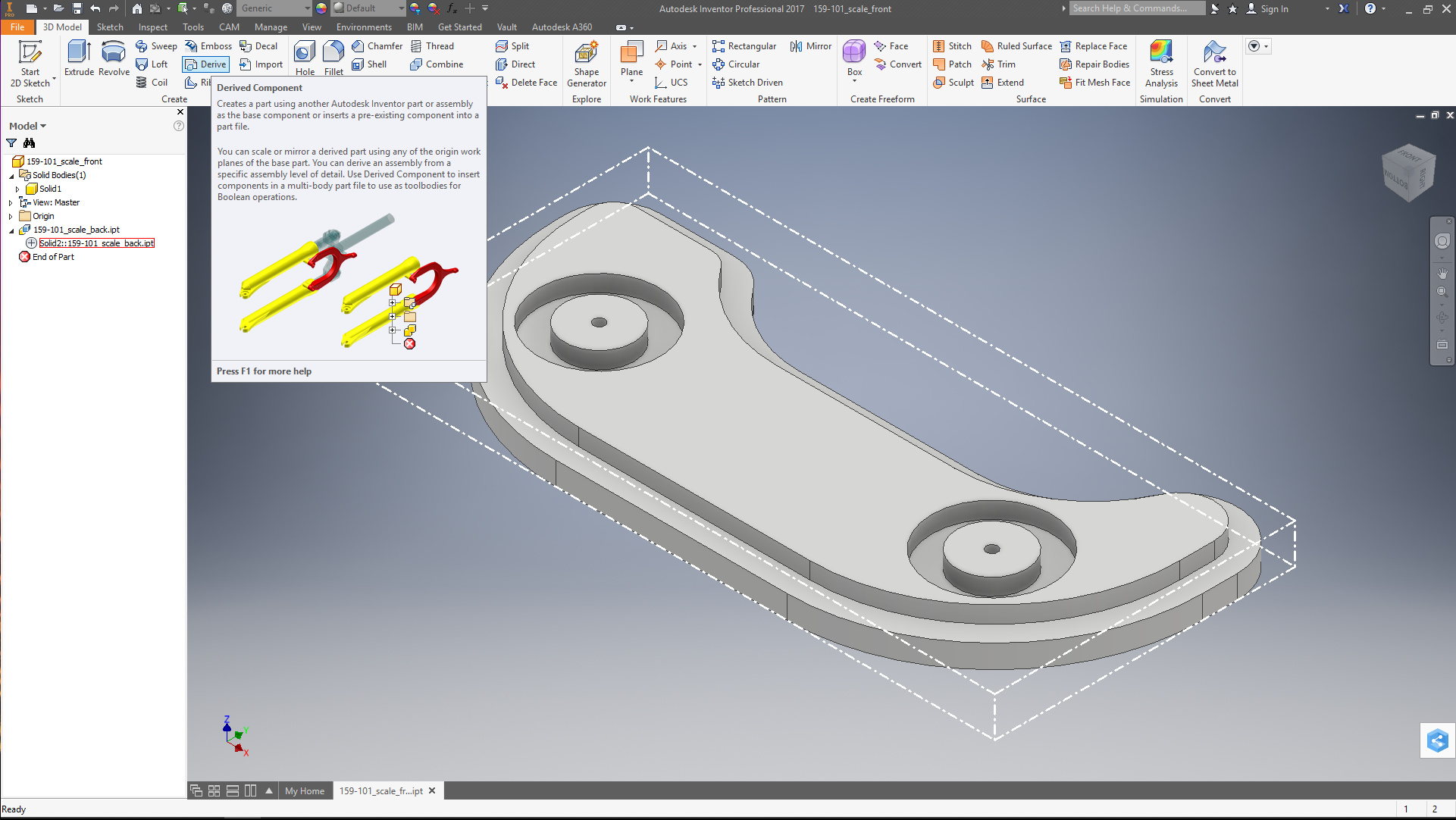
The CAD/CAM work was done in Inventor (Fusion360 would be essentially identical, and it could be done in Carbide Create with a bit more work). I won’t show the details of building the model itself (measure, measure, measure, then profile and extrude), but there are a few key points. I wanted to be able to run a few test pars in Renshape to get the fit right, and to have a uniform overhang from the pocket, so I modelled the pocket actual size

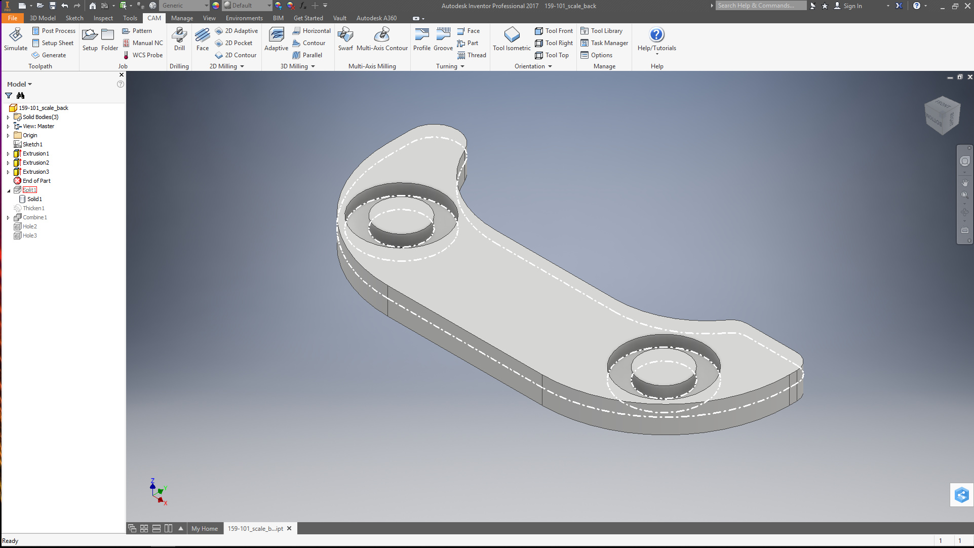
extended the profile down another 2mm, and split the piece into two parts. This allowed me to

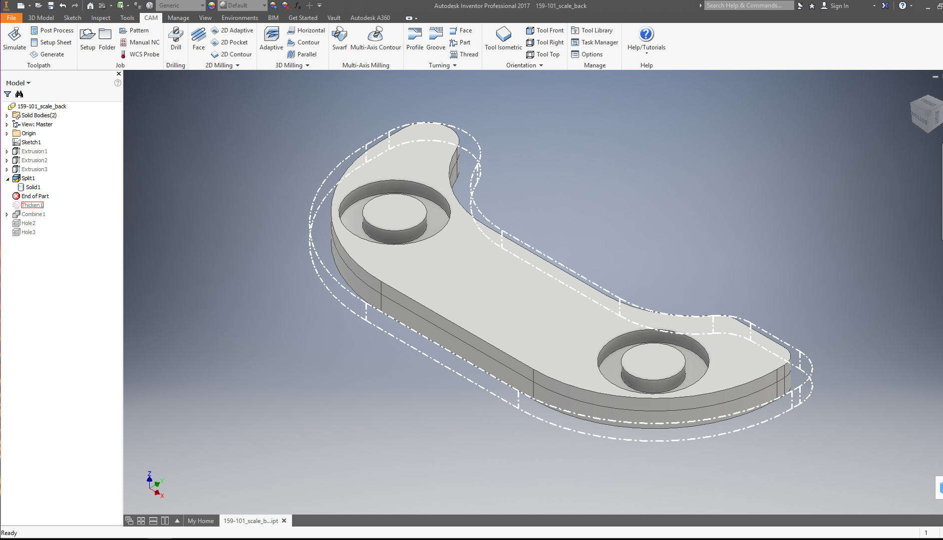
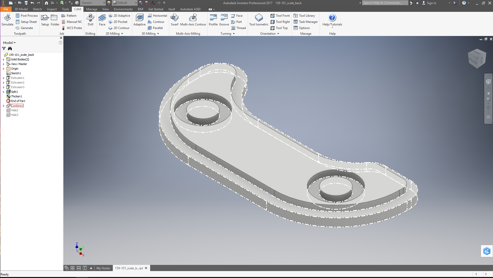
thicken the part above the surface and

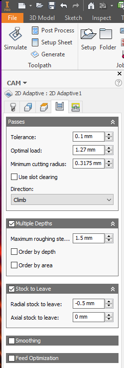
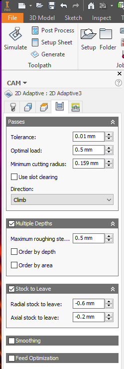
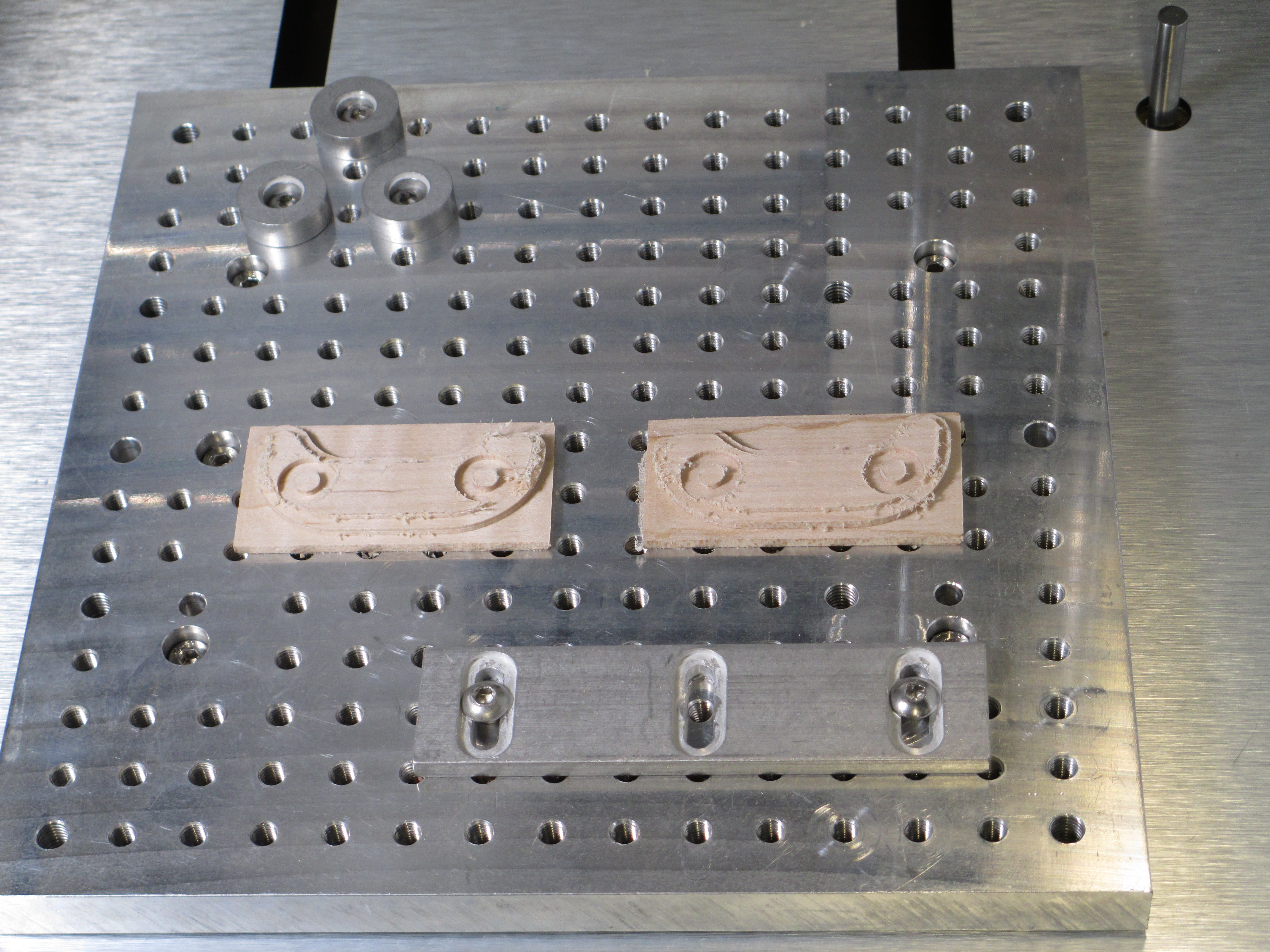
I ran about 5 test parts in Renshape for the first side (the back) to get everything to my liking, though two iterations were for CAM parameters (next post) for appropriate clearances to fillets and draft on the frame.

(continued)
recombine the pieces. I could now adjust the overhang as an independent parameter.

2 Likes

The CAM could be done with the free version of Inventor, Fusion360, Carbide Create, or and 2.5D capable CAM.

First operation was for the profile that fits into the frame. scales_d-first-cam-2dadaptive

Nothing special (select the profile at the bottom of the region and bBob’s your uncle) other than one CAM parameter:

Note the “Stock to Leave” is negative. That gave clearance for the radius and draft where the web meets the flange of the frame. Second time was the charm for this.

Next was the profile for the over-flush portion of the grips.

scales_e-second-cam-2dadaptive

Note the height selection for the top is selected as the plane between the reduced part and the exposed part.

Then came the grooves for the flange around the through holes

Again, the “Stock to Leave” was used for clearance (second time was the charm on this, as well), and axial clearance was left, as the flange edges around the holes was a bit dinged, and some was raised a little. I could have done this with any of several tools, but due to the small width of the groove, and the small diameter of the tool, the fastest and least likely to damage the tool was a trochoidal (adaptive). For this, not a bit deal either way time wise (only a few minutes), but these small tools cost a lot.

For the other side, I made another part as a derived part.

flipping over the y-z plane (a check box on the derive dialog) to reverse left-to-right. This means the top side scale will follow changes to the bottom. The cam ops were copied directly from the first side, and all parameters copy except the region selections (propagating these can lead to really big issues in some cases, like trying to cut from the wrong side through the finish part) so I will not show this.

(next up: the product)

3 Likes

Now the machining:

I won’t show the test parts, since I took no pics. Ran them, test fit without removing the material from the machine bed, decked the material and ran the revision.

For the finish parts, I cut the stock with a hand saw and decked it to 5mm in the machine after mounting (3M 0.002" 467MP adhesive). The pieces were mounted so the Y and Z references were the same, and the X differed by 80mm so I only needed to zero once (the bar at the bottom is parallel to the x axis, and I know the Y absolute location, so I used a parallel between it and the work). Decked the pieces (CAMed up a surfacing op at Z=0 for the stock size) and ran the jobs. About 20 minutes after I pulled the material from the small cuts box, I had

Whaled through this at 10KRPM and 2m/min with a 3.2mm two flute, and 10KRPM, 1m/min with a 1.6mm two flute for the circular groove.

I did not cut all of the way down (I left 1mm) to insure that the material would no pull free during machining. Clean up took about 5min by hand. If this was for production, I would make up a fixture and flip the part to clean up the rest. 1 min of machining to do it, but a couple hours to set up the fixture for locating and holding, so a fretsaw and Vixen file it was.

The grain is somewhat apparent here, but what really makes it pop was a light sanding with 400 and 800 followed by a few shots of lacquer.

It is really tough to get a good photo of.

Last was mount the scales. They were bedded in epoxy.

The thicknesses were to provide good support when the tool is lying flat. They match the counter box and thimble, so the tool isn’t lying on a corner or supported by the thimble.

Now, one pimped out Mitutoyo.

7 Likes

Beautiful! It’s always wonderful to see great old tools with nothing really wrong with the “working parts” brought back to life!