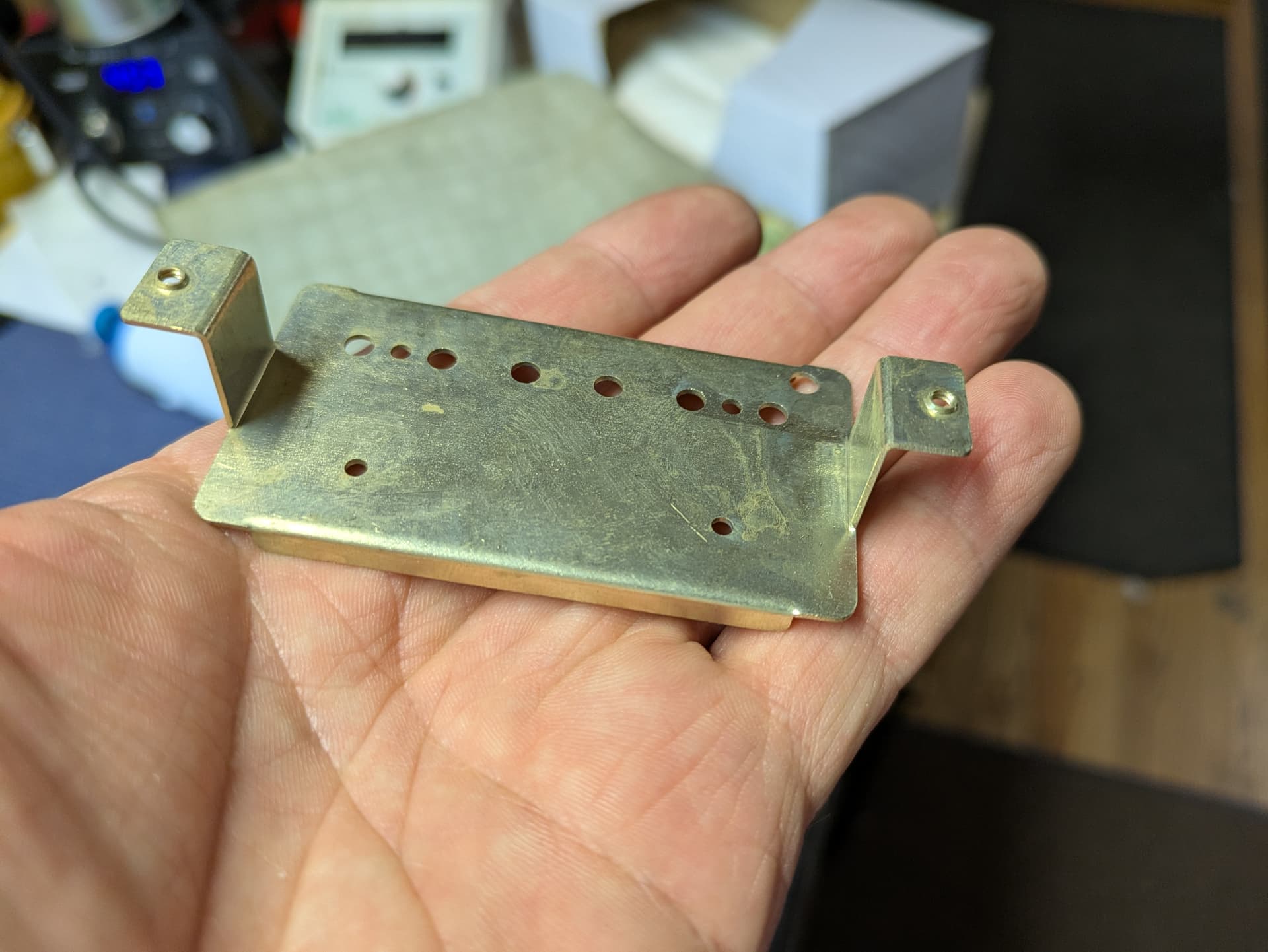
I’m wanting to use a v bit to engrave a logo on the bottom of the base plate in the picture I am attaching. For a work holder my idea is to make a recess in some MDF the thickness of the metal and come up with a way to have it stay in place. (maybe screws or if someone has a good recommendation) But my real question is how do I make sure my machine doesn’t hit the legs as it moves from part to part? Does making retract height more than the length of the legs avoid knocking into them, or is when the machine moves from work piece to work piece another adjustment?
Do you have more than one piece to do?
Regardless, a tall retract height will avoid the legs. Assuming you are using CC, all retracts go to the same height. Of course, this may end up taking a lot more time, because it will retract to full height every time.
EDIT: Feature request here, go give it a like if you think it’s a good idea.
The movement should be consistent for a given file — I usually set up a proxy of the complex part as cut out using Lego Bricks with connections oriented to allow them to break away if the machine moves into them, set the zero w/ a 1/4" probing pin, and run the job — if it hits anywhere, I add a no-op toolpath such as a very shallow Drill toolpath at an already cut away area to adjust how the machine moves and test again.
1 Like
Yes, a higher retract is the “safe” solution. But as mentioned it will add a lot of time to the path as it will retract to that height after each vector.
Fancier CAM software offers local & transition retracts, or uses a solid model to represent the part & retracts higher when necessary.
You can play around with multiple toolpaths & changing the cut order to ensure the paths begin & end at a spot where the rapid to the next part won’t collide.
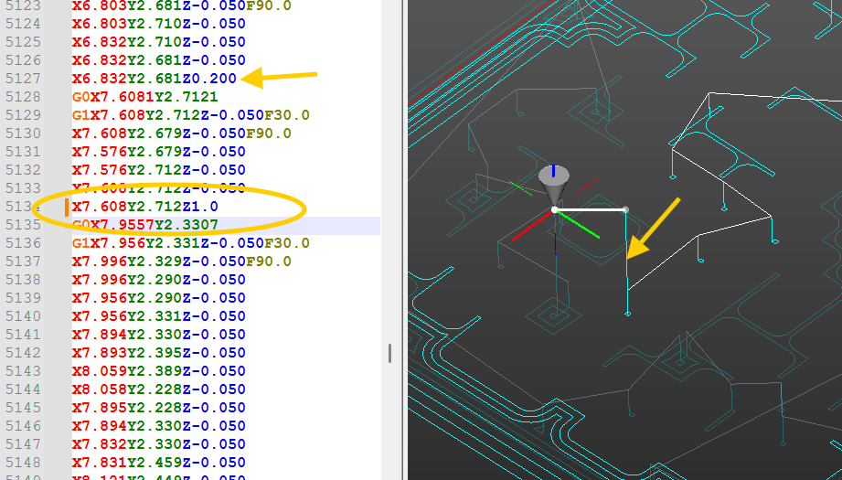
I would set the retracts to a low local height, then just edit the Gcode anywhere it looks like the retract needs to be higher. This is NCNetic plugin for Notepad++. Click on the retract in question & just change the height (In this case, from 0.200 to 1.0)
1 Like
Thanks for the replies. Both what I expected to hear but also some ideas. I am new to this so my CNC isn’t fully integrated into my work yet. Ideally I would like to do batches of these, but I’m not in a full production mode so one at a time as a last resort isn’t a big deal. I’m a luthier and this is supplemental to repair work for the time being. After I posted this I had the idea of using wood blocks (same idea as the legos I guess) and double stick them into the locations of the legs on some MDF and just do some test runs. They would just get knocked over and nothing gets damaged. The retract height taking a long time isn’t much of a concern right now either. Yeah, batches would be nice to do but I’m in the mindset of making dozens not thousands of these. I’ll look into the no-op tool path if it really does take way too long to do. I’ll let you know how it goes.
1 Like
Be sure to consider the size of your logo and the distance between those two legs. You want your router, router shaft, collet and bit to fit in between the two legs while engraving. Likely any dust collection boot will need to be removed. The retract height will prevent running into the uprights during rapids but will not keep you from bumping into the sides of the uprights if your logo is too wide for the router to fit inside them.
I use painters tape and super glue very successfully on a variety of projects. You put painters tape on the bed of the Shapeoko and painters tape on the bottom of your part and put super glue in between. Give it a few minutes to dry before machining. When done I use a putty knife to lift the tape off the spoilboard and peel it off the project. I use TiteBond medium viscosity super glue and just 2" wide 3m blue painters tape.
This topic was automatically closed 30 days after the last reply. New replies are no longer allowed.