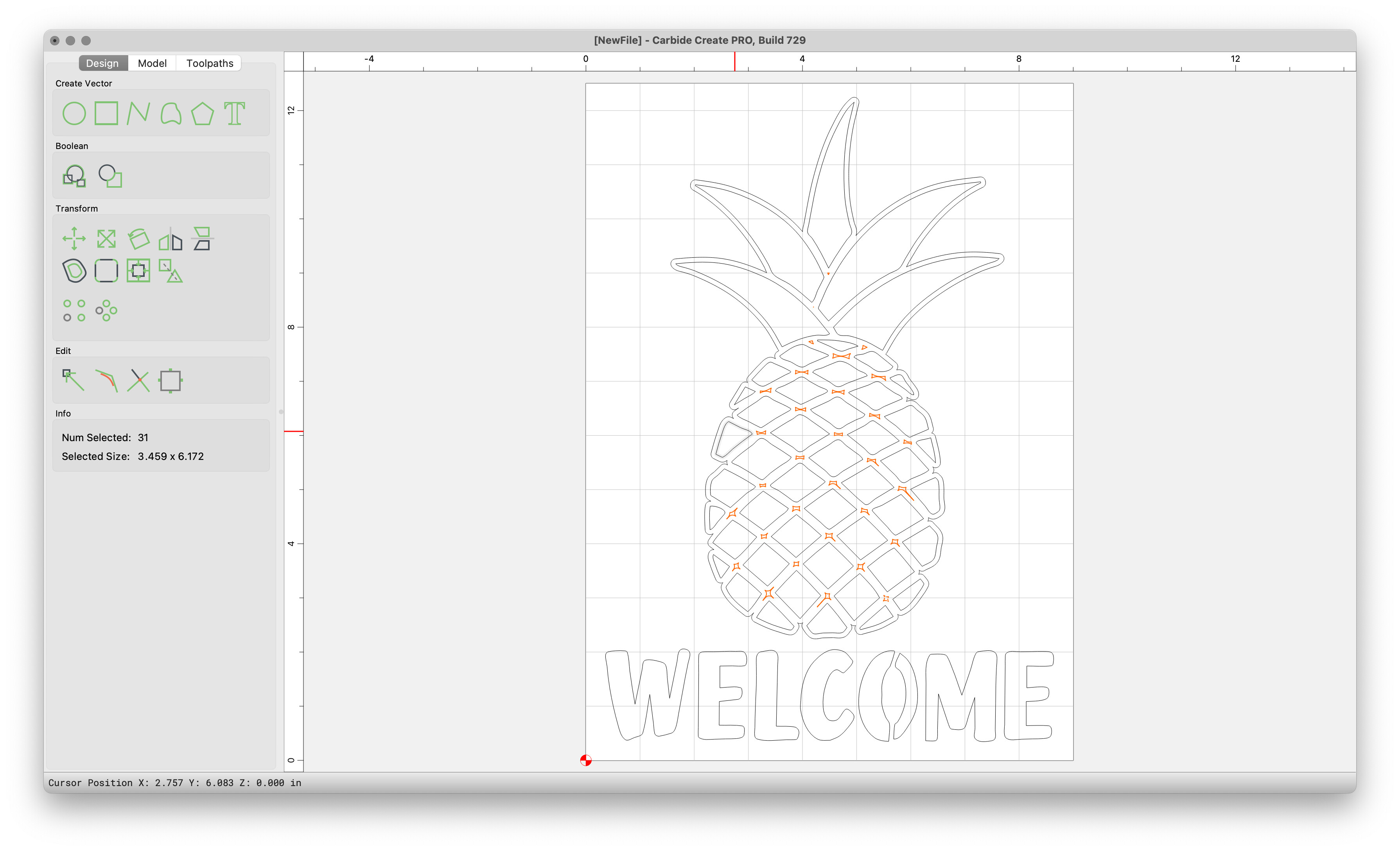
like the title says I want to create a toolpath that will be in the middle of various shapes, like a vcarve path, but don’t want the z axis to move up and down (change depth) along the path like a vcarve would. for example if I want run a roundover or vbit along all of the white lines below but not have different depths. a contour path for each shape would leave some bits in the middle. and a vcarve will create deeper spots at all intersections. I might be overthinking this but who knows.

Easiest way is to offset to the outside:
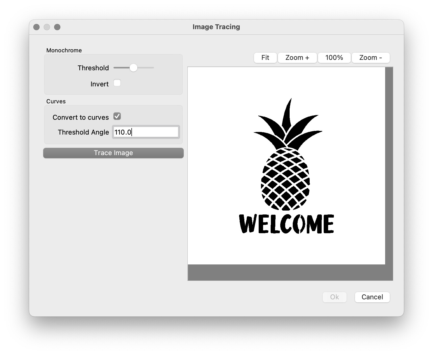
Import the image by Image Tracing:
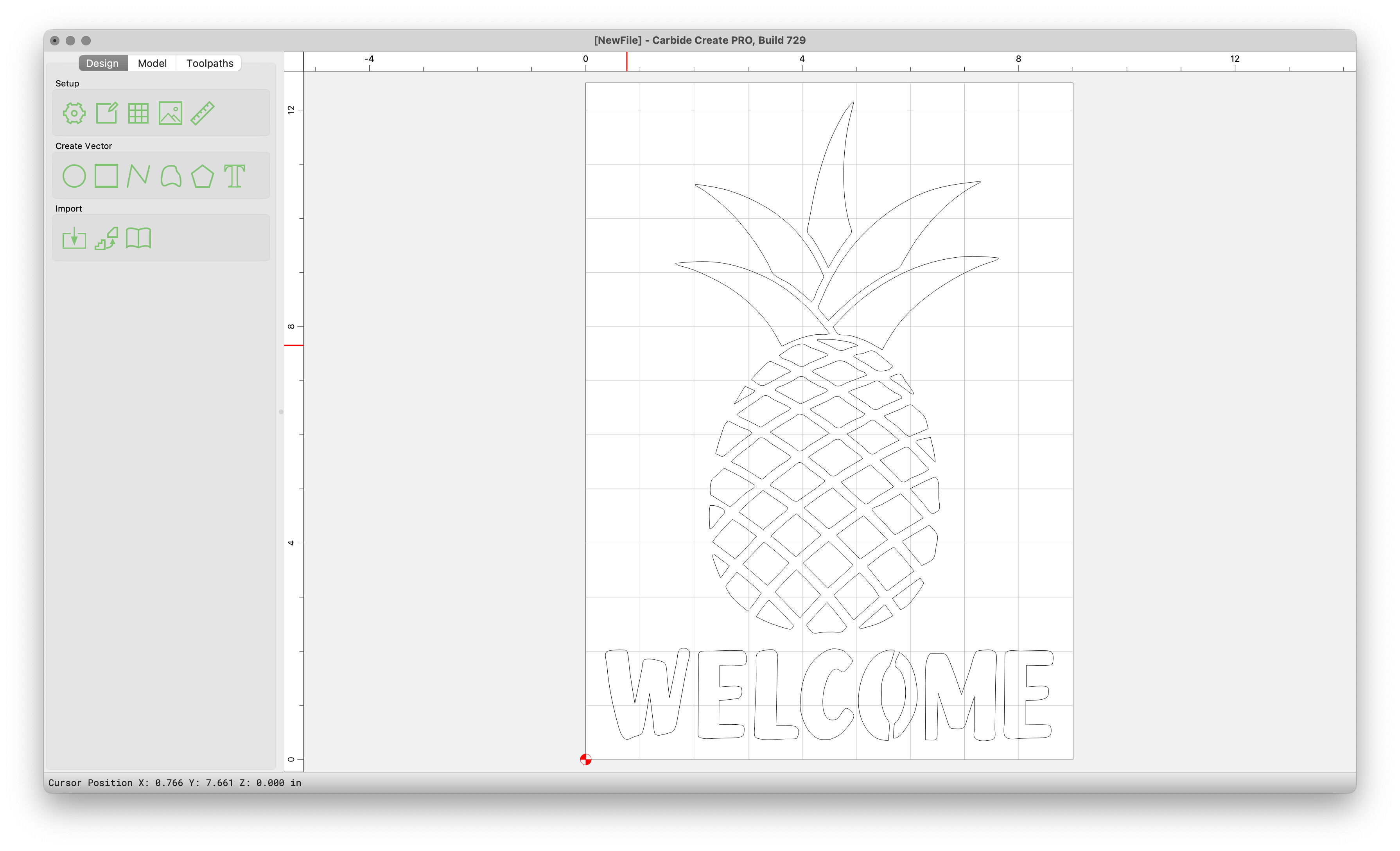
Select the regions where you wish things cut thus:

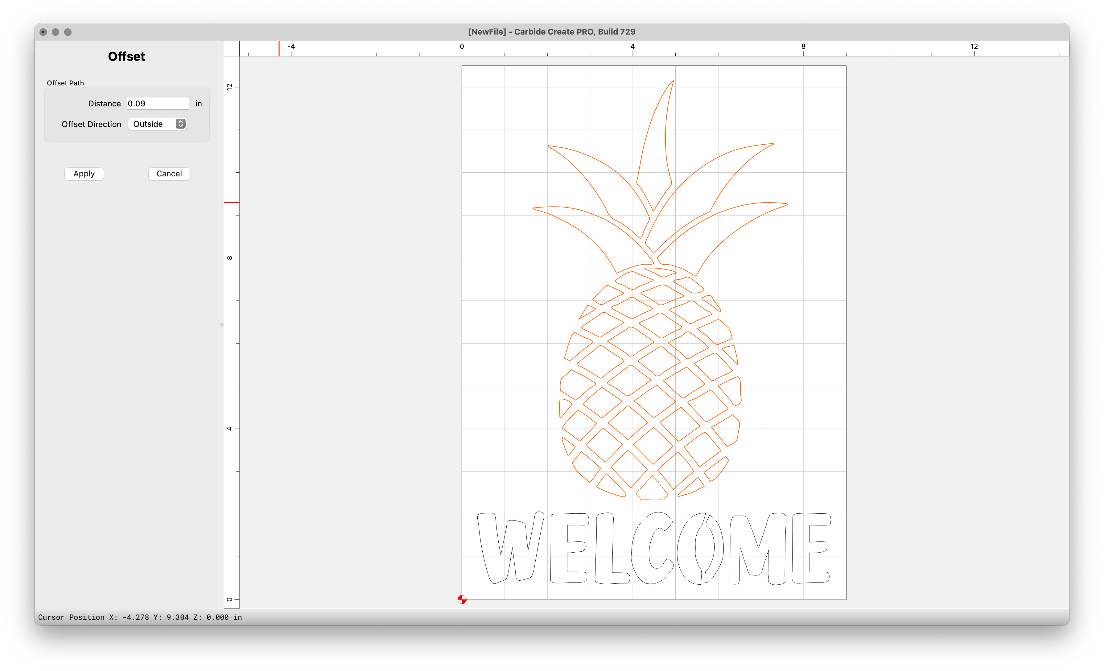
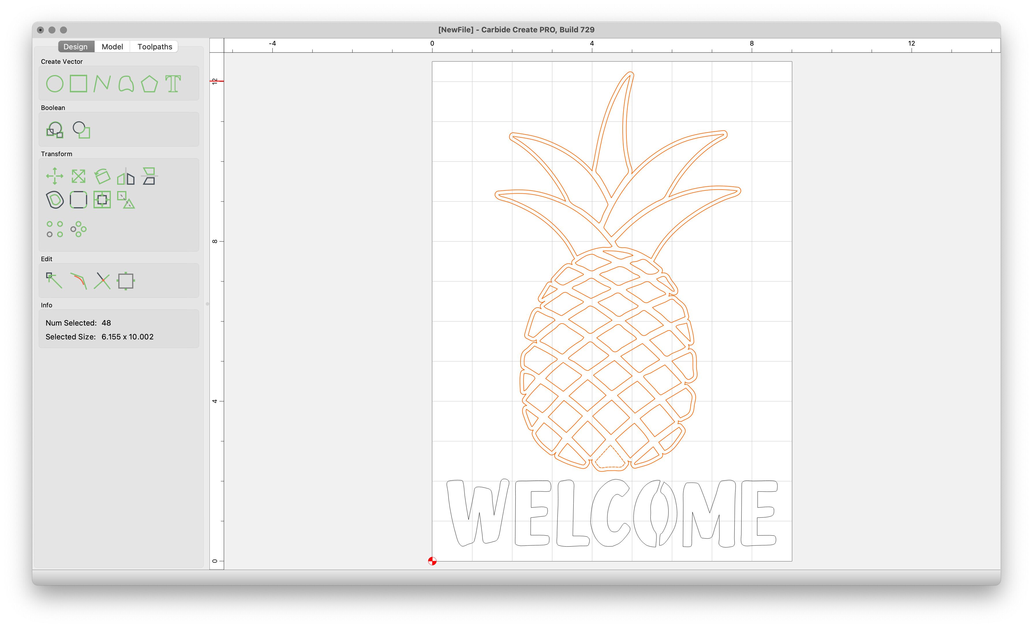
Offset to the outside by the width desired:
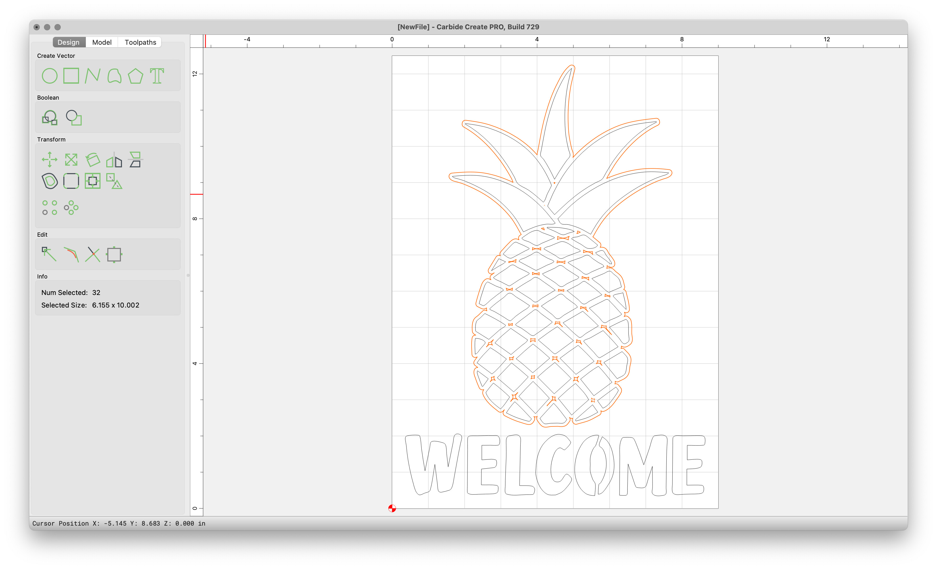
Deselect the outside (which we wish to keep):
and delete the small bits, then select what one wishes to cut (optional step, clean up the edges of the design via node editing), then select what one wishes to cut:
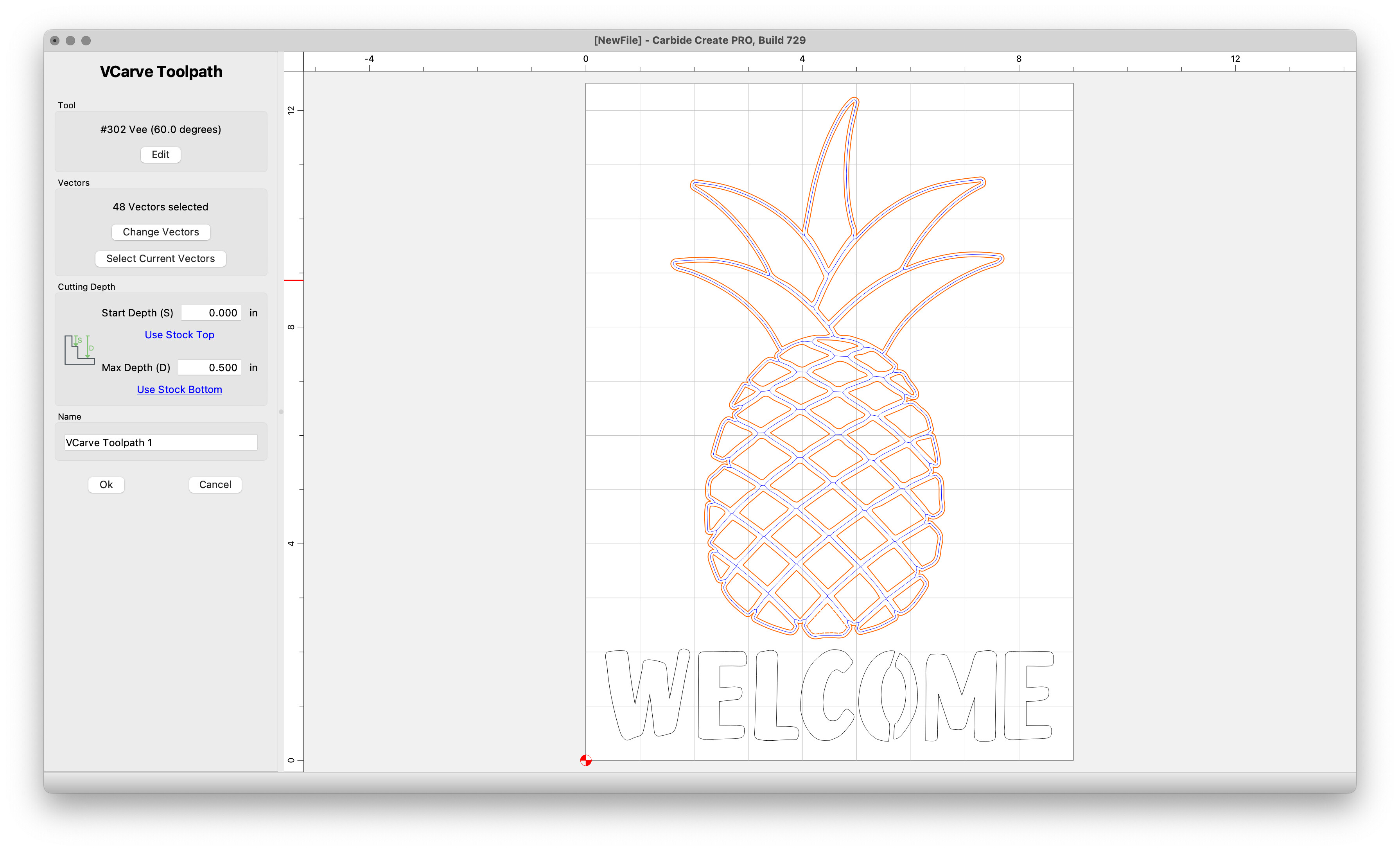
and assign a V carving or Advanced V carving toolpath:
ya thats what I did already, but it got me thinking if there was another way. I am sure it will be fine, like I said I was just wondering if I could get that path but use it as a contour in order to avoid the depth changes that are inherent with vcarves (because I had planned on running a roundover bit). Guess I will run it like it is with 60° and figure out from there if I need to switch it up and manually lay out a path.
If the space in-between the spaces is even/regular enough you can offset to the outside by slightly less than half the width and then use a no offset contour w/ a V endmill in a recent version of Carbide Create — it won’t be exact, but it will work.
The other option would be to node edit/draw in the interstices.
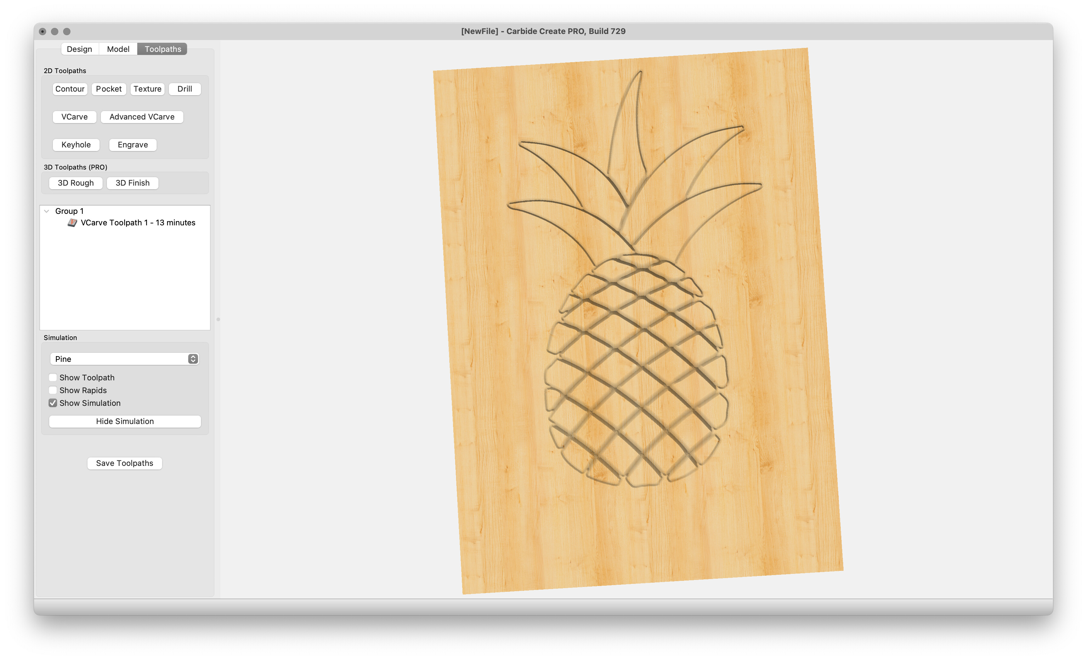
You could just run a Vcarve and set the maximum depth to say .125".
Run it and see what happens. If you are not happy you can always make the max depth deeper or the start depth deeper.
1 Like
You can use “Trace” command.
like I said earlier, I had already used the trace command to get the image and a vcarve to get the path. I originally wanted to use a roundover bit which is why I wanted a set depth as I was worried about repeatedly plunging. In the end I just ran it with a 60° v bit as a standard vcarve.
But the idea of being able to create median paths between objects that don’t have to follow vcarve logic could be helpful in certain builds which is why i was asking if there was some workaround rather than trying to perfectly line up a bunch of off sets or manually placing a bunch of straight line vectors and editing nodes.
just wanted to touch back on this. Decided to try something and had ok results, so figured I would share for anyone who might want to do the same.
I haven’t actually tried cutting this way yet but it should work (I think). As a workaround I created a vcarve tool path that I wanted to follow then screenshotted the onscreen image, saved it, and then used that image to trace. It wasn’t the cleanest line to follow, but I am guessing if I play with the image zoom in or out a little and change the threshold I can maybe clean it up. Again the whole point of this is so that I can maintain a constant depth through the cut instead of changing the height in the corners.
this project was a one off so I don’t really need it anymore now I just want to figure it out for my own sake.
2 Likes
This topic was automatically closed after 30 days. New replies are no longer allowed.