I am very new to Carbide create and motion. Is there anyway for the spindle to jog the perimeter of the work to ensure it is zeroed and lined up correctly before you start milling?
There isn’t a native feature for this this.
You can create a separate file which has a stock thickness greater than the clamps (so as to clear them) and run a perimeter pass thus.
When you load your file in CM, You can see the paths your router is going to take. If need be adjust your clams to avoid collisions. You can also adjust the retract height taller than your clamps to avoid collisions.
You can create a perimeter using the ‘Offset Vectors’ function, then program a contour path on that to show the outline. You would then set your Z Zero higher than usual so that no cutting occurs.
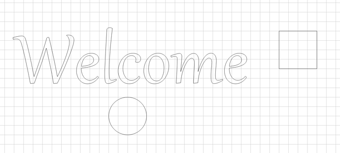
Here’s a few random things I dropped in a project as an example:
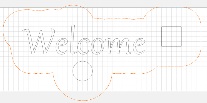
Select everything, do ‘Offset Vectors’, and choose direction ‘Outside’, and use an offset value that is larger than any closed area in the project (for example, the circle or square). I used 2" in this case:
Now select that, and do 'Inside Offset by the same amount, and delete the outermost one:
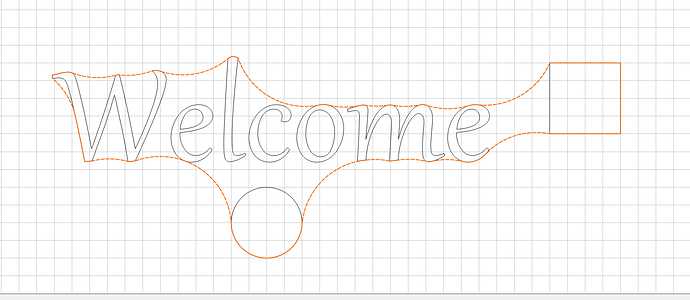
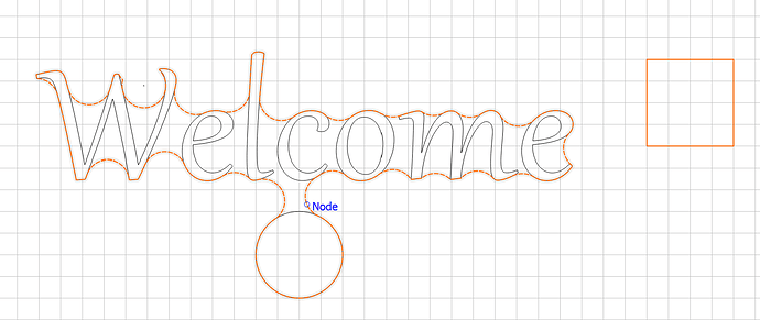
If you want your outline to hug the project closer, just use a smaller offset. Smaller offsets may end up with more than one outline vector. Here’s the same, using offsets of 0.5":
First let me say, Will Adams will never guide you in the wrong direction.
In Carbide Create the feature you ask about isn’t there. However, if you follow a few simple steps, you should be fine.
To me, it sounds as though you either have experience or have watched videos of lasers.
- When starting a project, I make sure to have the dimensions of my work piece spot on in Carbide Create.
- Then design the project on those dimensions. This assures me that the cuts will be where I put them.
- Most of the time Bottom Left is my Zero point. If different than that I usually triple check my zero point is correct for Carbide Motion. For my machine SPXXL the zero holds true project after project, unless there is a limit switch failure, or I have changed it for that specific project.
- When loading the program into Carbide Motion I always check the ISO View of the preview. If all looks well, I continue with the setup and Z- Zeroing.
If all the previous has been done correctly, I have yet to have anything off-kilter. Knock on Wood! ![]()
I hope this helps.
How do you view this path in motion? Thanks for the response.
When you load the file you can click on the different views to see the tool paths. You know where your bit is starting from and you know where the bit will go when the job is completed. Looking at the paths will help you paint a picture as to where it is going.
Good luck
This topic was automatically closed after 30 days. New replies are no longer allowed.


