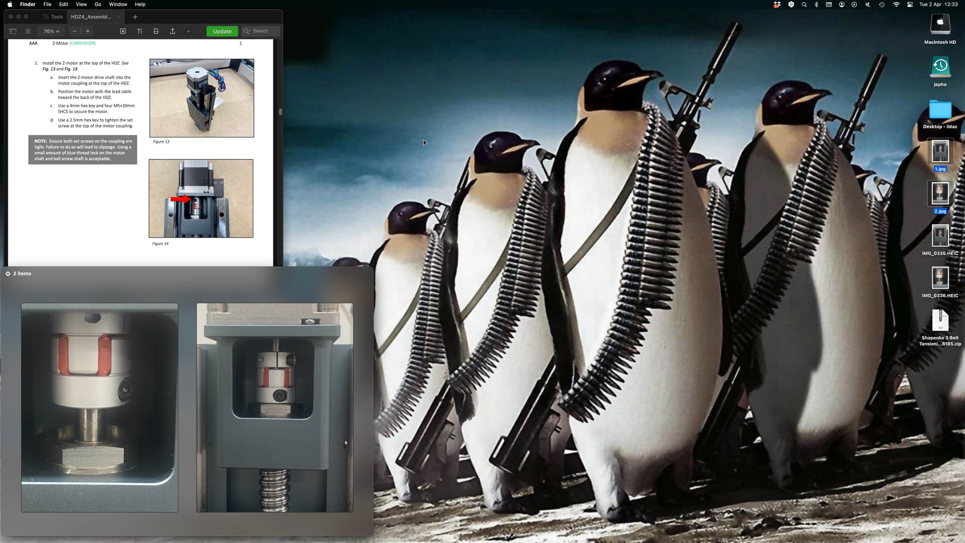
I am looking at page 18 of the assembly guide for HDZ 4.0. The lower image on page 14 shows a red arrow pointing to the coupling between the supplied stepper motor and the ballscrew. I appear to have a much larger space between the coupling and the ballscrew. The nut just under the coupling in the assembly guide image suggests that there is not much in the way of space to spare.
I have taken a screen shot so that I can show all three relevant images together. The images show how much space lies between the coupling and the nut if I raise the coupling so that it grips the motor shaft sufficiently. Alternatively, the space that remains above the coupling if I leave it resting on the nut.
My intuition is that the coupling must grip as much of the stepper motor shaft as it can to make the best connection. It is not clear to me how I ensure that the coupling is gripping the flat of the stepper motor shaft. I would appreciate some assistance with assembling this part of the HDZ upgrade correctly. Thank you.
I can’t recall if the coupler is machined so that the flat has to engage a matching flat section (I don’t think so, that would probably be expensive to make) — it’s pretty rare for a slipping coupler to be a problem for an HDZ so long as it was tightened correctly initially (they have a huge mechanical advantage in terms of applying forces).
I’m sure @Luke will know the specifics of the current coupler setup and be better able to advise/explain.
OK, thank you. The image in the assembly manual mislead me. Is there any particular way to know that the flat on the stepper motor shaft is optimally engaged? Do you have the torque settings I should use?
A further issue is I have just discovered that there were no extended proximity switches in the packet. So two of them are too taught and wont fit in the control board without applying strain to the cables.
The machine is a standard sized SO3 and the items are are on page 7 of the assembly handbook for HDZ 4.0. All of the items listed at the bottom of the page under the subheading Proximity Switch Baggie are absent. I do not require item ‘S’ as noted in the listing. I am missing items ‘P’, ‘Q’ and ‘R’. What photos are you in need of?