I managed to remove stock through 2D Contour and Adaptive clearing.
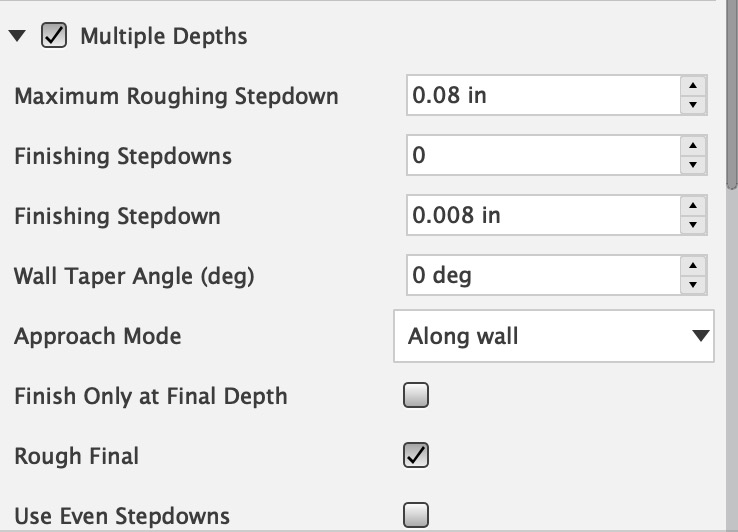
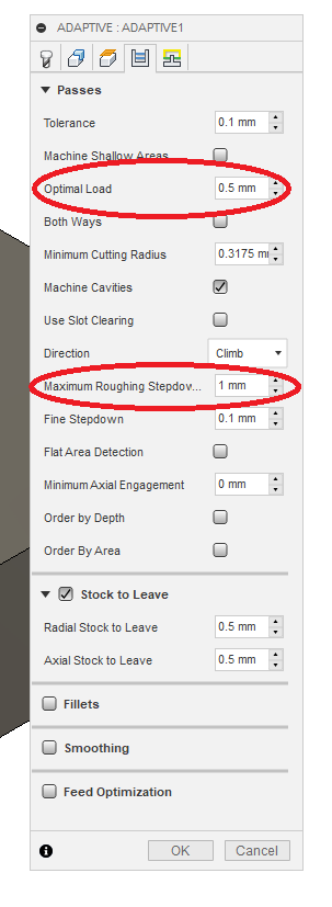
Now in the 3D Adaptive operation, I don’t understand how to reduce the amount the cutter cuts into brass. The first tool path cut into the left inner ring deeper than I’d like it to and then on the 2nd pass it went so deep that I immediately stopped the operation in fear of breaking my end mill. In the Passes tab, I reduced the Maximum Roughing Step down but that didn’t help.
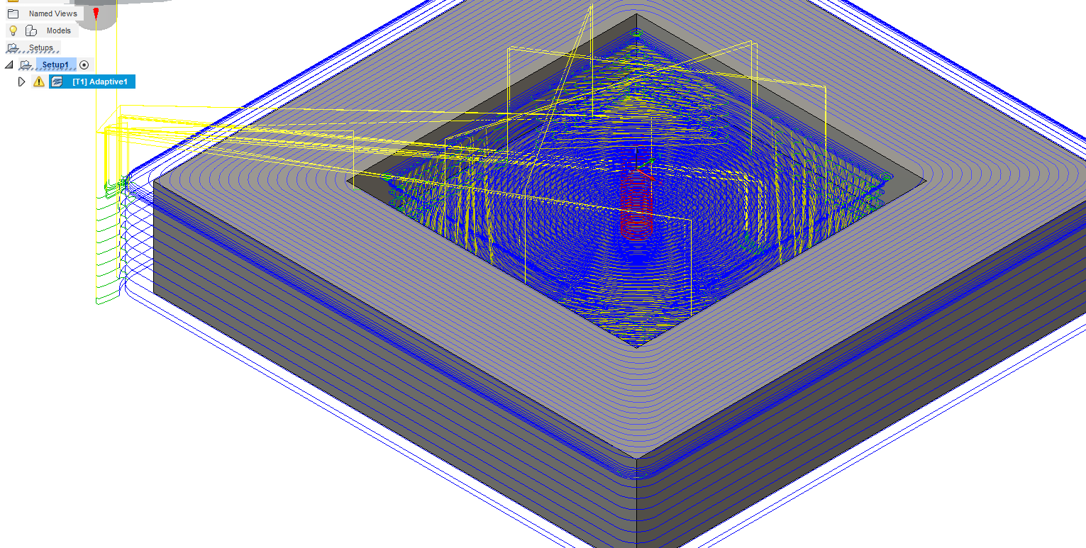
The 3D Adaptive tool path shows multiple depths alright but the problem is initially because it’s roughing from the previous operation, it cuts too deep into the brass.
My Optimal Load shows as 1.27. Is that the problem? Should that be less?
The optimal load defaults to 40% of the tool diameter. This is a good value for many materials and situations, but needs to be taken with a large grain of salt on a smaller machine and with smaller tools, especially in tougher materials.
As noted by @neilferreri, there is a tradeoff between depth of cut and tool engagement. In many cases, you get better tool life and greater efficiency with greater depth of cut and reduced engagement, but there is a limit. When the engagement is too low, the chips don’t take the heat with them, and, at the limit, the tool begins to rub (tool deflection, machine stiffness, and the material properties all contribute, so there is not single rule to know where this begins).
Keep in mind that the end of the tool isn’t the most efficient part: the edge speed drops toward the center, the corners on a square-end tool are the weak points, and this is where the deflection will be maximum. Greater depth and reduced engagement spreads the wear over more of the cutting edge, reduces deflection in general, and takes a lot of the work away from the corners of the tool, as well as giving more consistent cutting-edge speed.
The worst case is slotting, where the work is all done with the end of the tool and at all times, there is a point on the end of the tool that is stationary with respect to the workpiece, as well as a portion of the cutting edge near the center (on the ‘climbing’ side) that is being dragged backwards, and therefore rubbing, not cutting. (Slotting also tends to push the tool to the left, and has poor chip evacuation with a tendency to a lot of chip recutting. I really hate slotting.) Using a tool engagement less than about 40% avoids these issues, so it is really a balance of other things that control.
@enl_public - Thank you very much for the detailed explanation. I’m still new to CAM and it can get pretty complicated sometimes, especially if you don’t have anyone to compare with.
Much appreciated!
I would say scallop was the right choice, as it gives a uniform surface stepover, giving a consistent finish quality from flat to nearly vertical.
Morph spiral is useful for arbitrary regions that are somewhat round and within maybe 45 degrees of level. Further from level gets poor results, as it tries to use near constant stepover in x-y, rather than on the surface. Elliptical, amoeba shaped, whatever. Regular spiral doesn’t do a great job if the region isn’t basically circular or annular in profile.
Better finish can be achieved several ways:
Using a ball end that is larger radius or smaller stepover. There isn’t a lot of benefit to a stepover less than 1/4 the ball end diameter, with the smaller diameter tools. Use rest machining with smaller tools and correspondingly smaller stepover to get into the corners.
Using a consistent surface angle and using a vee tool with a matching angle. This can be a bit difficult, as very small issues with machine calibration, squareness, or tool angle will leave hard edges in the work piece that can be tough to get rid of.
What ever you do, you will not get a perfectly smooth, mirror surface. I would final finish with 400 grit wet-or-dry (wet, with kero, WD40, alcohol, or other thin coolant) on a wooden mandrel (flat for the spokes and convex, slight radius for the concave) to take the scalloping down, then your choice of final finish (finer papers up to polish, scotchbrite for a buff finish, scuff with courser paper, whatever)
@enl_public - It took me 3 repeat reads of your reply to wrap my head around what you mean. Thank you! I’m not sure I can swing all steps but it’s good to know and attempt to follow
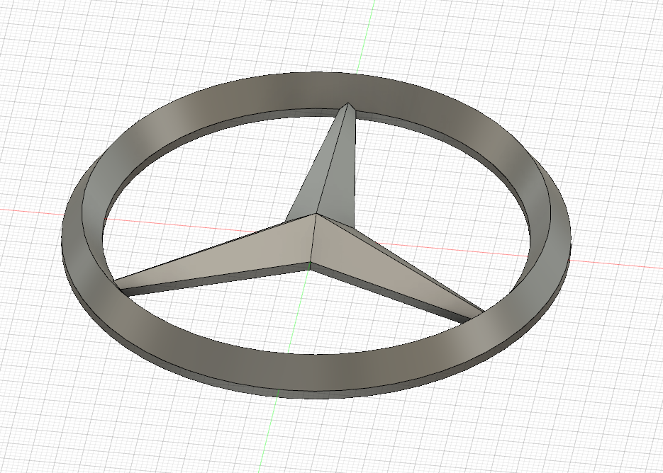
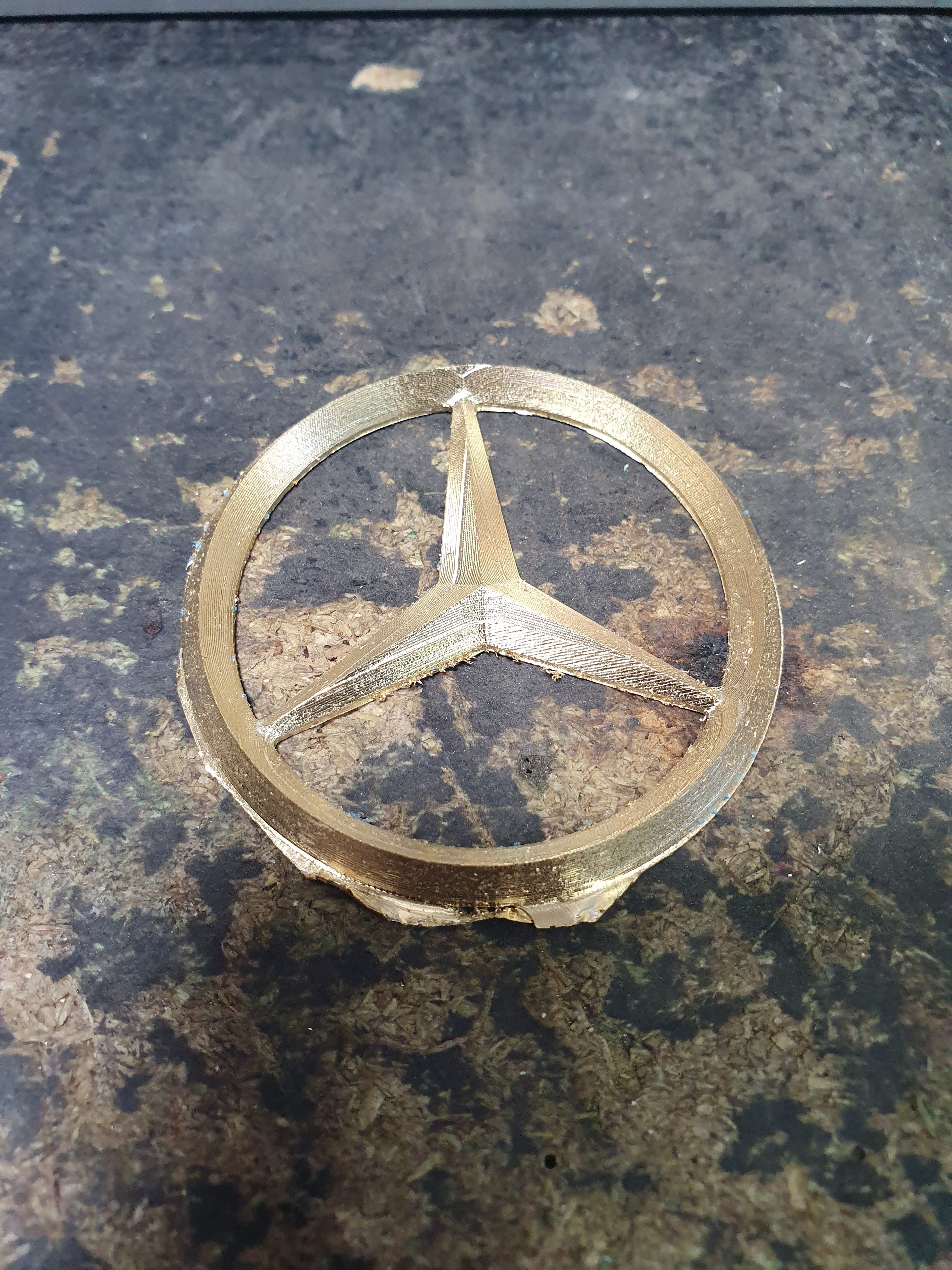
This is eventually going to be a belt buckle for a customer. Never done one before but figure I’ll learn a lot in the process. And I have.
Morph spiral generally provides a much smoother toolpath than scallop and I personally see awesome results up to almost 90 degrees…if setup correctly. Its also one of the versatile toolpaths imo.
Also not sure if I agree with 25%D on the ball milling, depending on part shape and desired runtime…smaller steppovers = better finish.
Not sure how to make it clearer without writing a book (which is something I tend towards and active work to avoid) while Inventor builds toolpaths. Trying to get the cycle time for a part down to <30min. Initial (using just 3D-adaptive to get a starting point value) came in at 1.5hours, with 4 (5?) tools. Hard part is limiting an operation to the correct region, while getting all of it. It is a decidedly non-trivial part, with deep, narrow slots and compound-curved surfaces that meet flat areas that must be FLAT (so square end tool), with surfaces that must be avoided and risk of tool and toolholder collisions.
Of course, 5 to 10 minutes for a path gives time to shift focus, which can help give a fresh look if it doesn’t meet requirements.
(other sidetrack is a circuit board for a stepper-type gauge movement, sensor, and uController)