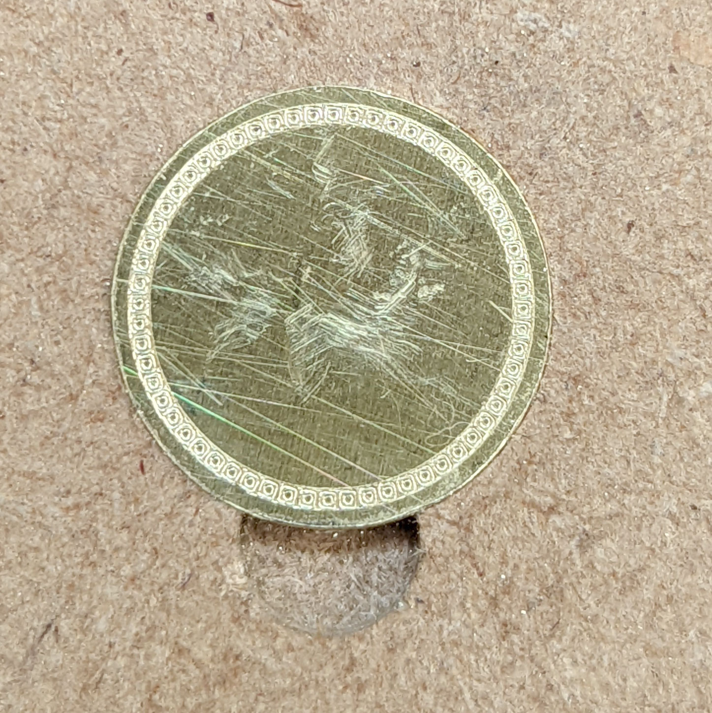
Much appreciated! Also Rob, could I request you to have a look at an issue I’ve been battling with for 2 months, with the same file? After etching the pattern, the cut out circle around it doesn’t cut concentrically.
Many thanks!
Gunter
Much appreciated! Also Rob, could I request you to have a look at an issue I’ve been battling with for 2 months, with the same file? After etching the pattern, the cut out circle around it doesn’t cut concentrically.
Many thanks!
Gunter
The inconsistent cutting is probably mechanical — create a new post or e-mail support@carbide3d to open a support ticket on it?
Thanks Will, I’ve been communicating with support since 10 May!
Gunter
The person you’ve been working w/ has been in and out of the office for a while — we’re checking if someone else can chime in.
Things to check:
I’d be immensely grateful if you could fix this as I have been at the end of my tether with this issue for 2 months now!
Yes, I’m combining drag engraving and cutting. First drag, tool change then cutting. I suspect things go off after tool change but don’t know this for sure. I have also tried running both toolpaths separately but that hasn’t helped.
I used 3 Mcetchers (2 I purchased and 1 sent by support) in case something was wrong with one of them. All yielded the same result. I experimented with various degrees of twisting the screw at the end of the Mcetcher, none change the issue.
I have used a 10 degree vtip engraver (as a substitute for the diamond drag tool) but again, after the pattern is etched and the tool is changed to a 1mm end mill, and I think it’s that cut that isn’t concentric.
I have created a chamfer around the circumference with a larger Vbit and it seems to follow the perimeter fine.
Yes, I’m cutting a slot (contour tool path) around the perimeter. Again, over the last couple of months I’ve experimented with various depths of cut with very similar results.
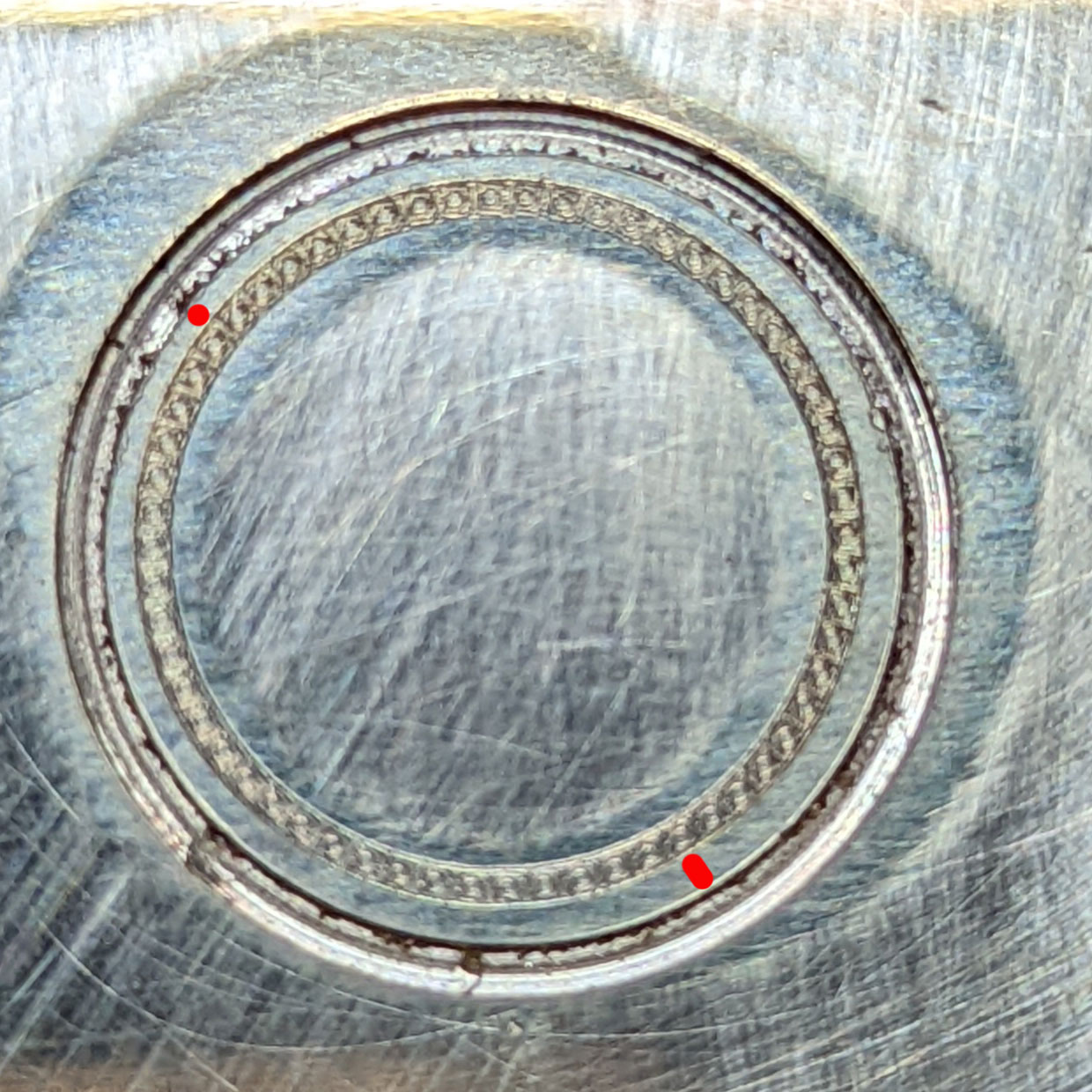
I also experimented using the Mcetcher instead of the 1mm end mill - just to see if the concentricity
is achieved and it seems to which, to me, indicates that something with the tool change might be the case.
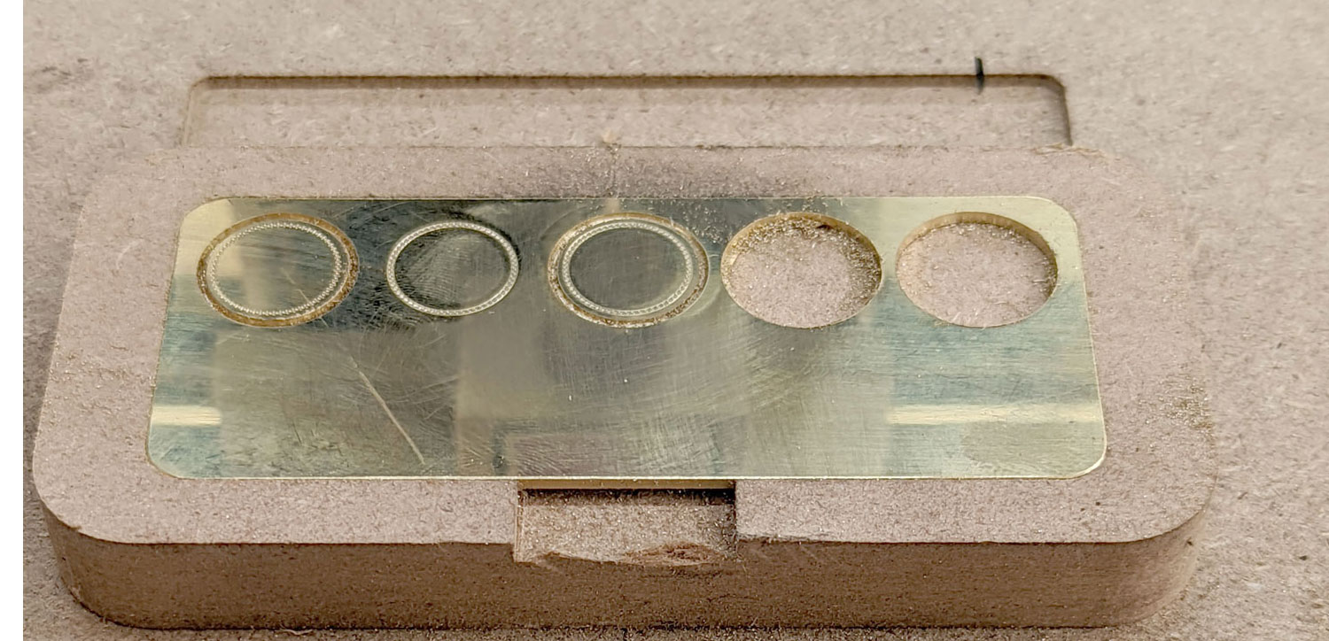
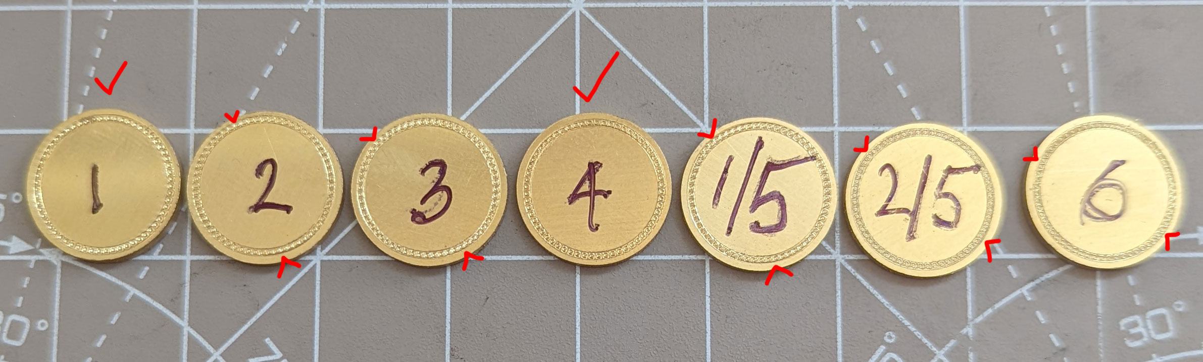
In case this helps, I checked the variance in diameter of the cut outs on various numbered tests:
[https://photos.google.com/share/AF1QipPdCNs8arzbo0QauIKK8A4-BEhB-6E0iv_Lcf4oBXNsCR0JrR7YJculTkzubiaWJQ?key=TFNLZXFsc09yUVNvTmVwYjhud2c1UHFRQXk3cjZn](https://photos.google.com/share/AF1QipPdCNs8arzbo0QauIKK8A4-BEhB-6E0iv_Lcf4oBXNsCR0JrR7YJculTkzubiaWJQ?key=TFNLZXFsc09yUVNvTmVwYjhud2c1UHFRQXk3cjZn)
Please do let me know if you need any additional info.
Gunter
I’m going to yield to what the folks this is assigned to at support come up w/ — hopefully they’ll have a resolution presently.
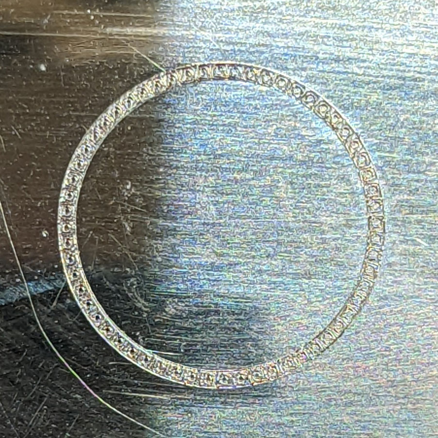
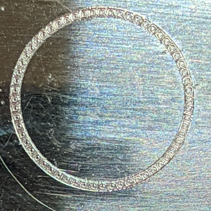
I reduced the pressure on the back of MC Etcher and ran the etch twice:
First etch:
Second etch:
I’m on the Nomad 3, how would I measure the runout?
I tried to measure the (runout?) cut outs in previous testing here:
Gunter
Did you run the cutout toolpath again?
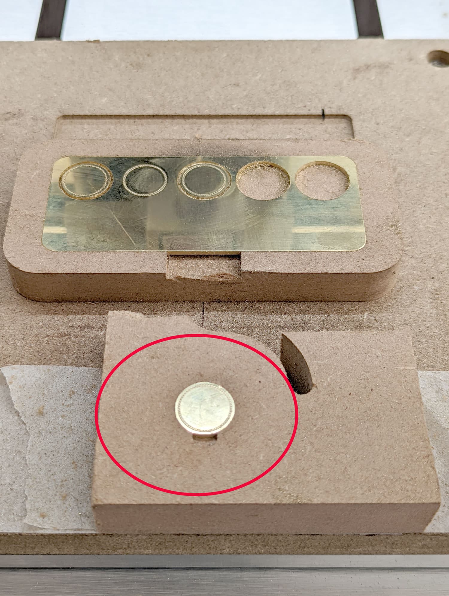
I spent the weekend on a last ditch effort to try one last method to test this. I decided to create a second
jig down from the centre line for only 1 pc, rather than 10. In the original jig, I cut out one disc.
With the disc firmly in the 2nd jig, I ran the pattern file with MC Etcher and results are good.
I repeated this twice to make sure it wasn’t a fluke, and the second one was as good as the first.
After 2 months at this, I’m relieved that my Nomad 3 CAN produce this result. However, I need to produce small batches of these discs and doing them individually one by one is going to take too long.
So, all we need to do is repeat this in the 10pc jig so I can bang them out.
I really hope you can help with that. I attached the latest file I use for the 10pc operation.
MASTER 10pcs to cut out of 100x50 brass sheet with pattern NEW.c2d (956 KB)
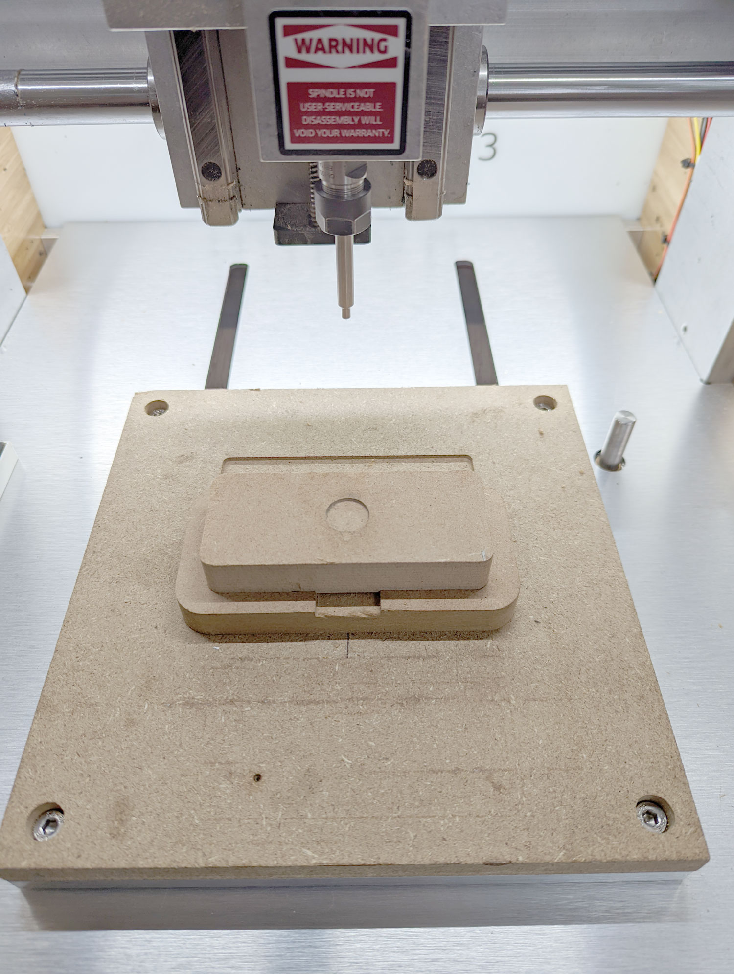
To create a cleaner workspace I made the single piece recess in mdf again, this time at 0,0:
Now, I’m getting the same non-concentric etch again ![]()
Gunter
Have you tried always using a new blank for the recess?
Or, have you tried making a fixture which you can secure the BitZero to and zero against?
Or, make a fixture which is conductive and which you could zero against inside the recess?
I wonder if the problem isn’t a variability in the homing process. Please contact support@carbide3d.com
Will, I use a new blank each time in the recess.
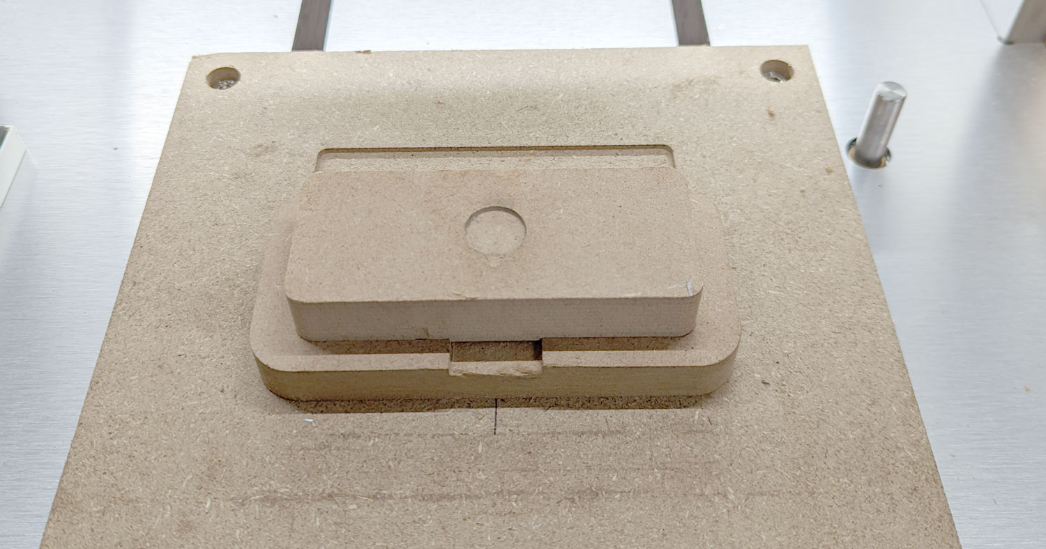
The original recess was designed to cut 10 pieces:
I then created another mdf jig that would fit within the recess for the 10pc plate to try etching one at a time:
I’m afraid, I don’t understand your other 2 questions.
I’ve been working with support on this for 2 months and I believe they’re sending me another replacement machine. My worry though, is that the issue persists on the new machine too.
Gunter
I will yield to what is determined on support.
This topic was automatically closed after 29 days. New replies are no longer allowed.