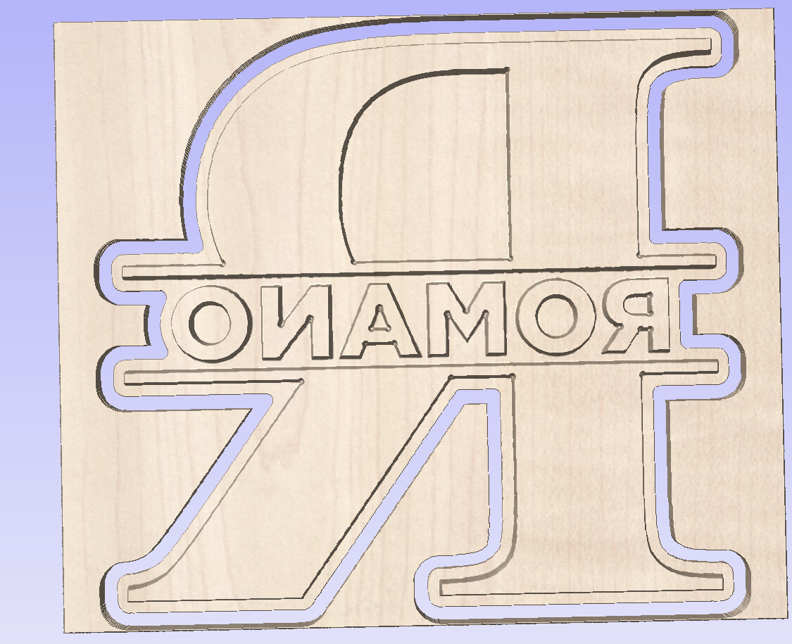
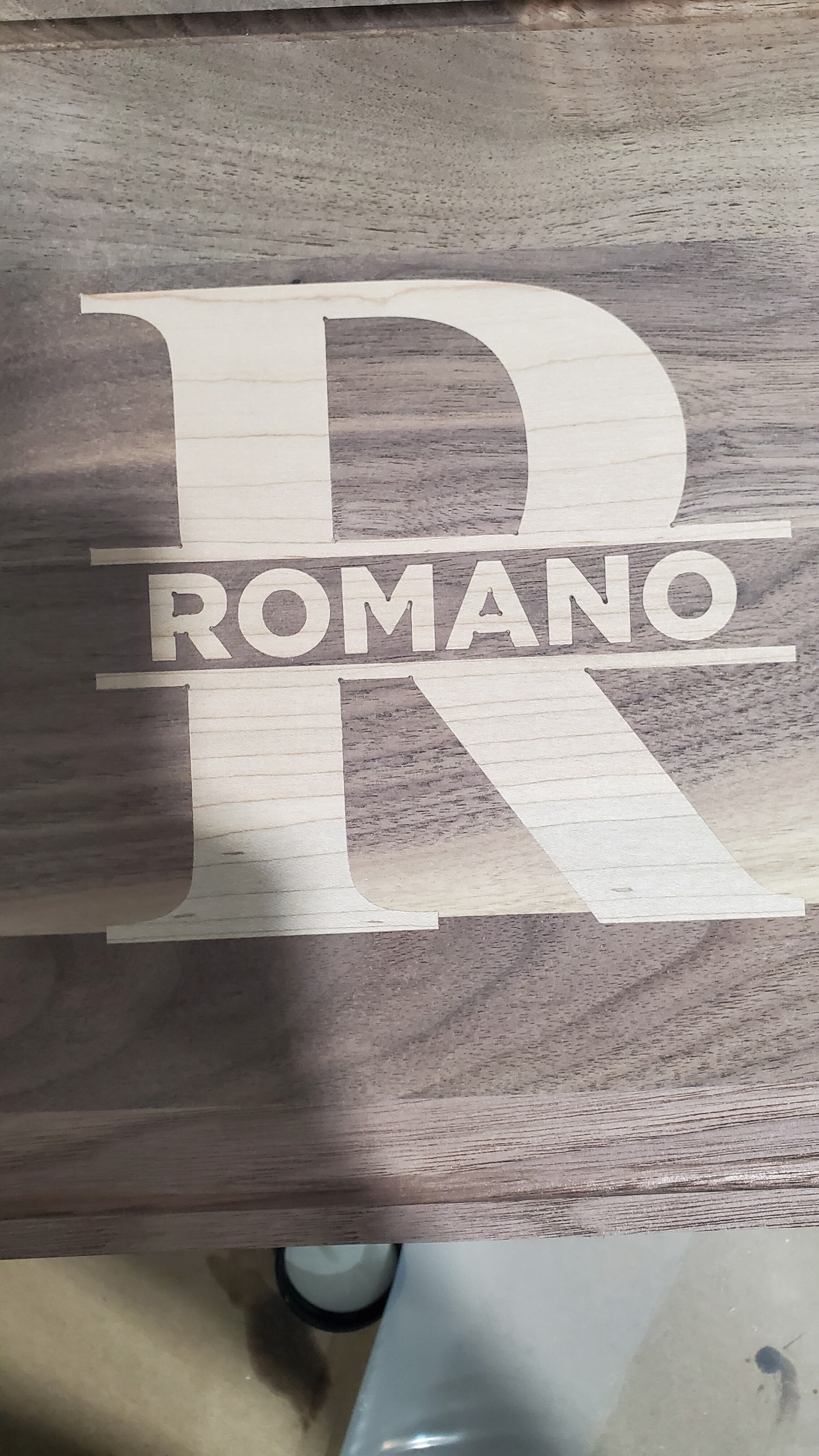
Im trying to make an inlay design, granted I am using Aspire, and for the plug side, the internal corners of the design (Like inside the letters) are rounded in. I am using an Amana 46280 bit, Ive seen people use it with great success, but Im me, so it has to be wrong lol. If anyone has any ideas on how to get around this that would be greatly appreciated.
Hey Nick!
Can you post the tool definition you have for the bit to make sure that looks like the bit itself?
And if possible the .crv file?
I believe the tool geometry should be fine, and how do I upload the file? it says its a not authorized file format? Thanks for your help!
You’ll need to zip 3rd party files in order to upload them here.
1 Like
Inlay.zip (412.4 KB)
Does it look ok if your start depth is at zero?
The male inlay won’t look great on its own…you’re looking at the part that won’t be seen from that angle.
no it still shows it on the final project. Not too sure what to try. Kinda tempted to put it in as a 12.4 deg v bit instead of a taper ball but idk if that would work. The model shows sharp corners but now sure if it would do anything weird
I followed the Vectric tutorials on this, and the various others on this forum, and if I’ve understood it from this your issue is that the inlay tool path is trying to use ‘a Vee’ cutter to run up vertically into the corners to make them sharp - but you have (and it should know) selected a Ball Nose cutter. I suspect the tool path is errantly (by Vectric) being created assuming a Vee.
After having made 10 or more inlays using this process, with Vee cutters, it does work correctly. I’ve never tried selecting a Ball Nose.
I see…I missed that you used a ballnose.
Yes, Aspire is assuming your bit has a perfectly sharp point when V-carving.
2 Likes
Perhaps try reclassifying the tool entry as a V-bit and not a ball end mill and re-running the preview?
I’ll give that a shot. So put it in as a 12.4 degree .25"? I did that and the corners look fine in the preview. Just want to confirm that those settings should be good
It’s a bit confusing since v-bits are specified for the full angle… but from looking at the tool it does appear the full angle is 12.4 and not the 6.2 in the spec.
Yeah I think the 6.2 is the half, so 12.4 would make it like a V bit right?
Alright well putting it in as a V mill didn’t work at all. Way too much play in the inlay now. I hsve zero idea how to correct for this
You would either need to use software which supports this tool geometry, or offset the toolpath geometry to allow for the radius tip and manually work up toolpaths.
Whats what im thinking. Just a quick sanity check, the diameter of the but is .03, so on each side of the female part would be .015 too much, to total error in the female part woukd be .03. The male side would have the same error, so in total, I woukd have to offset the make side by .03 to add .06 total to compensate? That sounds about right? Lol
I think we had a similar problem discussed on another thread. If the mill has a ball at the end, and you are pretending it is a v-bit, you probably have to estimate where the tip would be if this was truly a v-bit. It will be beyond the ball based on the triangle made by the angle.
You’d probably then have to jog that distance up in Z after zeroing, and then re-zero Z.
This topic was automatically closed 30 days after the last reply. New replies are no longer allowed.