What’s the width of the cutting slot that goes all around the piece ?
1 Like
Im doing a roughing and finishing pass contour with a max 6mm stepover though it only seems to be moving about 2mm. The total width of the contour seems to be about 7.5mm
Did you check the actual diameter of your endmill ? It may not be 6.35mm as advertised.
it is, its the stock 201 that came with the machine
At this point I think you should try a simple shape (square) with a simpler CAM approach (no roughing/finishing passes, just a single basic contour cut at low DOC) and see if it cuts accurately?
Please try re-tensioning the X-axis belt — that number seems a bit small, and usually the X-axis needs greater tension than the Y-axis. Then recalibrate the X-axis and verify the Y.
Ok, I will try those steps next.
So after a whole lot more test cuts and calibration, Ive managed to reliably cut a 100x100mm square (with a small 3mm DOC) to within acceptable tolerances (0.1mm).
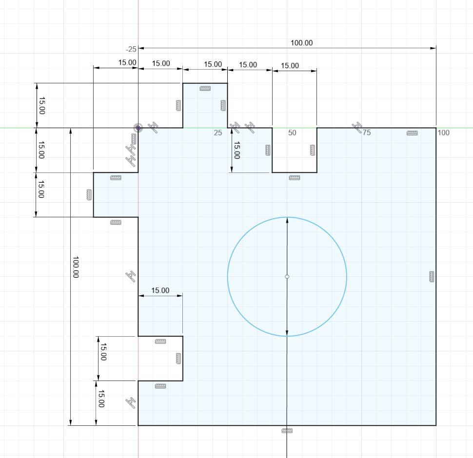
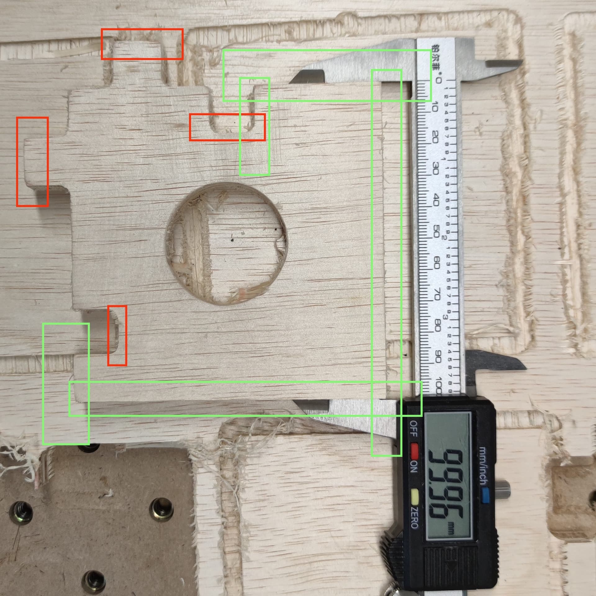
However, doing a test cut with a modified version of my previous file still yields issues with the grooves and fingers. I’ve removed the roughing and finishing pass on all toolpaths and the overall dimesions on exterior corners (excluding the finger joints) are accurate. The circle is about 2mm smaller than it should be but is otherwise circular (and not oblong). Ive attached a photo with correct dimensions in green and wrong dimensions in red.
I’m now inclined to think it’s got something to do with the gcode or CAM side. I’ve attached the gcode and f360 file as well.
Side note: I do hope to eventually migrate to cncjs completely, once i figure out how to use the neil’s macros for the bitsetter in there. Does all the calibration i’ve done in CM via MDI carry over?
I’ll try and have a look at the files later today (unless someone else does before then)
Yes, the $ values are stored by GRBL in the controller’s non volatile memory, and are used/applied regardless of which g-code sender is used.
Well I had a look at the two files, and re-read your latest post, and I can’t pinpoint anything.
The fusion360 when imported had invalid toolpaths/I had to re-select the contours, but other than that looks all ok. The gcode is fine too. Assuming a 1/4" endmill is used, that center hole should indeed be 40mm in diameter, from the gcode (33.65mm from one side of the circular motion to the other, plus 6.35mm, is the expected 40mm). Same for those finger joints. Running that gcode file should grant the correct dimension, so there is something mechanical going on. But if so, I don’t get how you can have both the correct dimension in X and Y on several parts, but not all. The circle being 2mm off is particularly weird.
I would normally ask you if you feel any play/wiggle in the router/Z axis, but you would likely not get the correct shape/edges if it were the case.
The only remaining lead could be deflection (but that would be a pretty severe case to give 2mm error on 40mm)
For the sake of testing, could you rerun that same piece, but toggling both contours from climb milling to conventional? (“Passes” tab, “Sideways compensation”, toggle to “right” instead of left for both toolpaths and regenerate/save gcode)
Snug all v wheels on the machine with their eccentric nuts. Recut with a 50% reduction in feed, maintain the same rpm you have been using. If it looks okay, try recut with your feed turned back up. You may have deflection of the entire router/tool combined. If your path is clockwise, inside notches would be undersized, outside tabs would be too large. Circle may be off different amounts in each axis (x and Y) but will be oversized. If your tool path is counter clockwise, what is undersized would become oversized, etc. Most of what you see seems to indicate a clockwise path with deflection.
This topic was automatically closed 30 days after the last reply. New replies are no longer allowed.