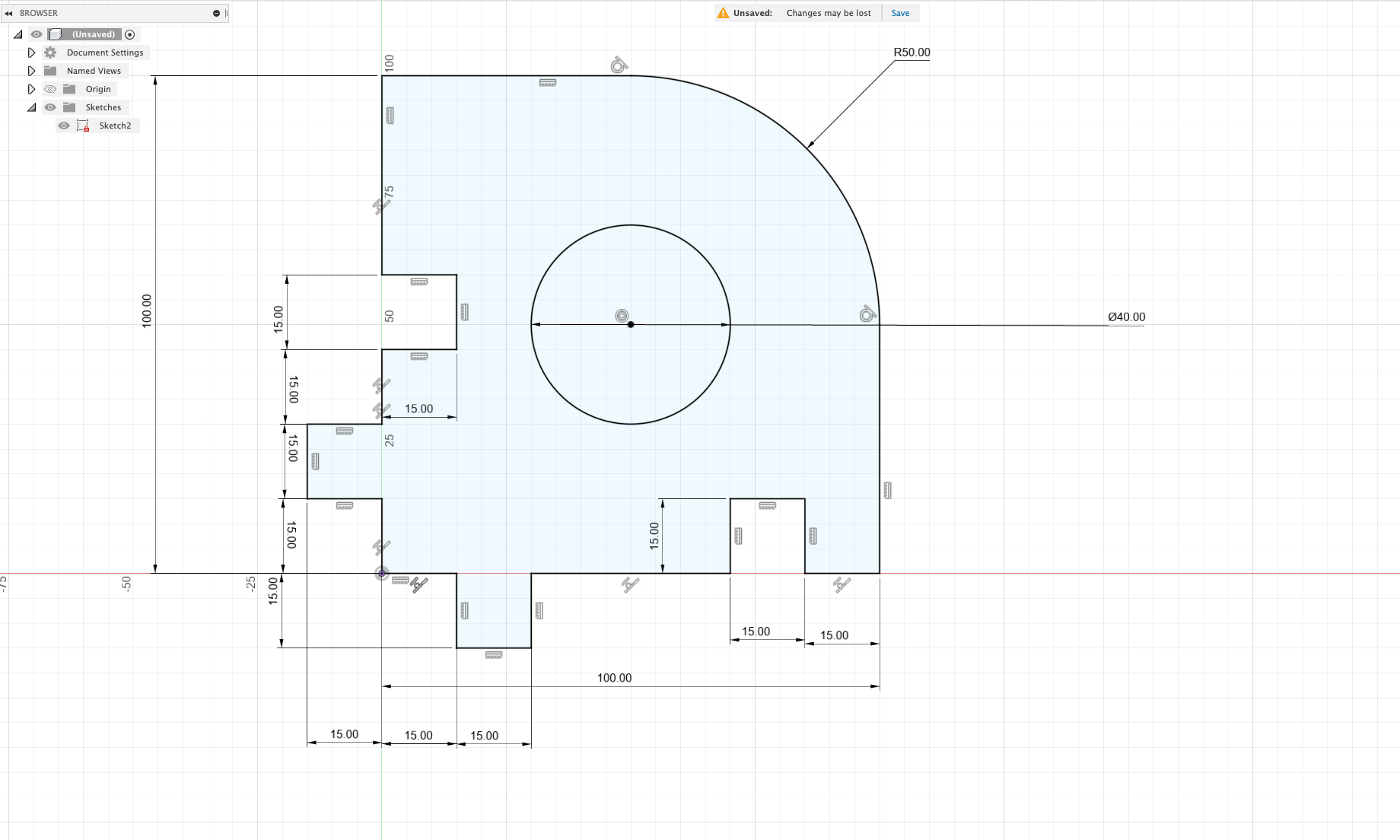
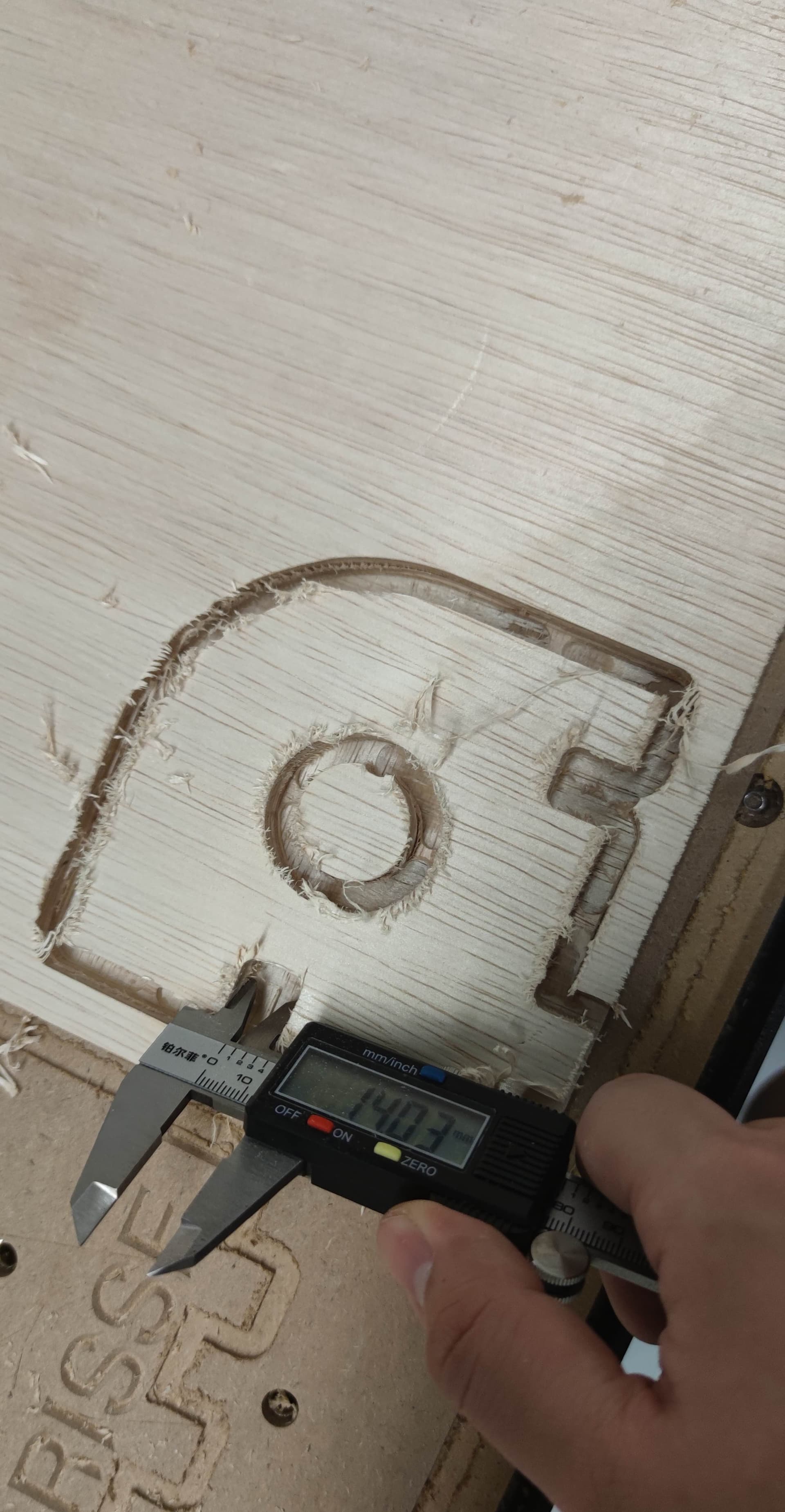
Ive tuned and tightened my belts multiple times and am confident they are as taut as they should be, however, i am still unable to achieve cuts within an acceptable tolerance. I’ve tried cutting both MDF and plywood. The issue is particularly pronounced when i try to cut finger joints and grooves. The protruding sections of the cut are larger than the specified cut and whilst the grooves to hold the joints are always smaller than the gcode. I’ve attached some photos to illustrate this, as well as my f360 file in case it turns out to be a CAM issue.
(EDIT: like Neil says) The Gcode and Fusion file are good, but looking at the gcode, the resulting cut is suspiciously similar to what would have happened if only the the roughing pass of the contour was executed, and it never got to the final contour finish pass.
The cut width for the final pass from the Gcode is 15mm as expect (taking into account the 6.35mm diameter of the tool), and the cut width for the roughing pass before that (the blue line on the left in this screenshot) is 13.73mm, which if you count tool deflection and possible measurement errors, looks close to the 14mm you are measuring.
BUT your pictures clearly show the inner circle being cut, so the job did make it to completion. Probably a coincidence.
Still, can you measure the diameter of that circle ? Is it off too from its 40mm target ?
True. Same for the circle being run after the rough & pass outer contours.
If the circle diameter is off, this will confirm this is deflection, mechanical, or both.
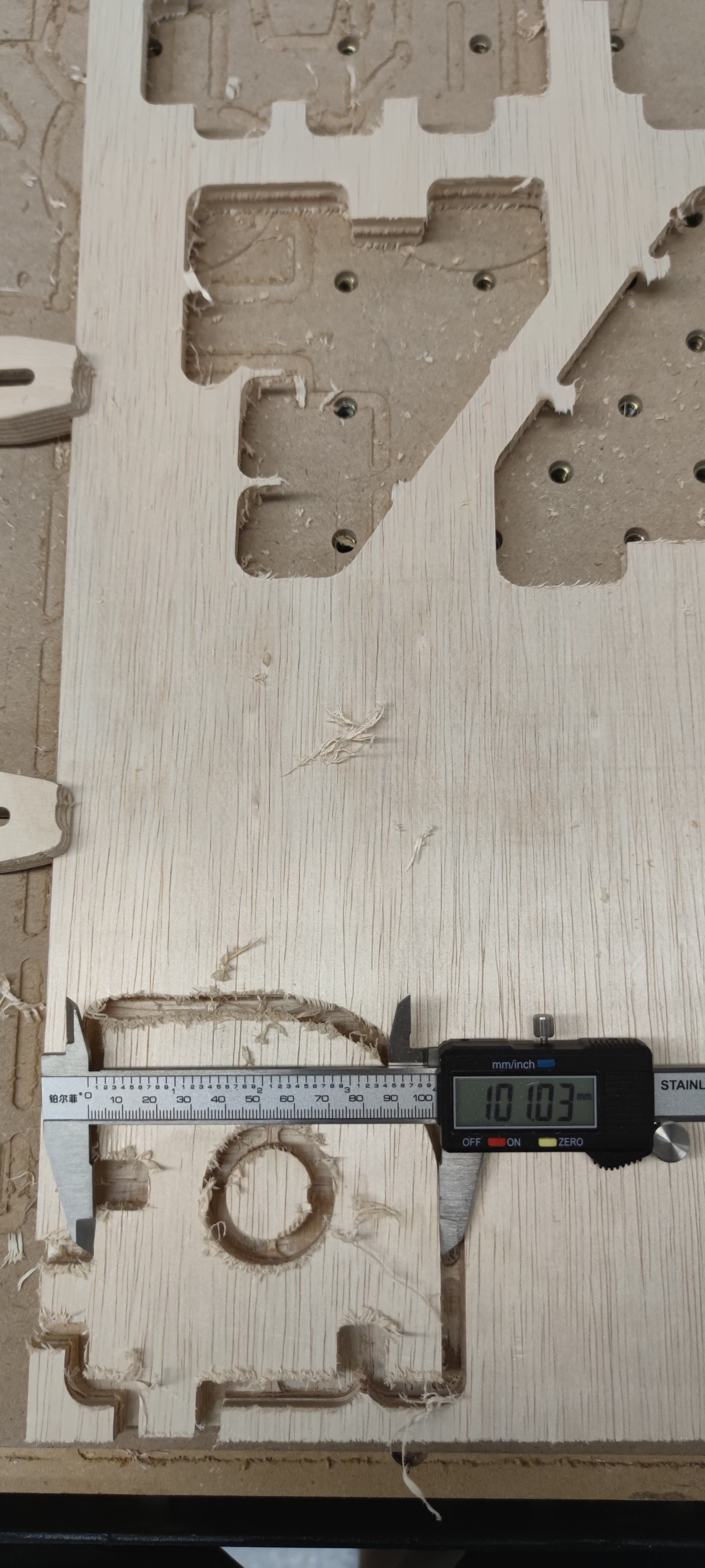
Just to add, the the depth is generally accurate, this particular job didnt cut all the way through because I placed the wrong dimensions for stock depth into the f360 file.
With regards to the top vs bottom are you referring to wether the width of the top face and the width of the bottom is different? I have not measure as I am out of of the office right now but I will do so next week.
The logical next steps (to pursue Will and Neil’s hunch) would be to jog the machine (for example by 100mm, near the surface of the wasteboard), and measure with a ruler how much it actually travelled. If it is not spot on, then some calibration test is a good idea.
I wrote a small bit about belt calibration here, if it helps (see X/Y/Z calibration section)
Ok. Deflection refers exclusively to tool movement during cutting i presume? Whereas mechanical might refer to a belt tension or vwheel friction issue?
As i mentioned earlier, ive run into this exact issue with cutting MDF, taking much smaller DOC (2mm) and had exactly the same result so I’m inclined to think it might be something mechanical.
Right, so this would tend to indicate that this is indeed a matter of calibrating the belt stretch, rather than deflection or something else mechanical. The “jog and measure” test will tell you. Ideally, use the longest ruler/tape your have, and jog all the length: the longer the movement, the more calibration error will show.
Is it possible to command the shapeoko to move by a set amount (say 100mm) via carbide motion or do I have to individually press the xy jog buttons a 100 times? Also, for the sake of ease of measurement, could just measure the movement of a specific point of the gantry (lets say i measure how far the edge with the limit switch moves) over a distance rather than trying to pinpoint the dead centre of the router bit?
So after measuring over a 600mm distance, I recalibrated the X & Y axis for belt tension slightly. The dimensions weren’t too off (603 and 600.8)
$100 = 39.80009
$101 = 39.96229
I did another calibration test cut with the previous file, changing the DOC from 7mm to 4mm. Unfortunately, the results are almost identical to my uncalibrated cut. The inner grooves and protruding joints are still smaller and wider respectively.