My first question.is; Is it a good idea to use a CNC to cut drawers for a full kitchen build? if not - we can go about this with the other shop methods.
If a good idea - I need some assistance in how to setup and adapt multiple sizes for the project. Would be happy to purchase a ready to use file to do this with.
QU2 Any one interested in helping me out. I’m Coachable!! But I’m new to the CNC world and have not dedicated enough time to become good at the machine.
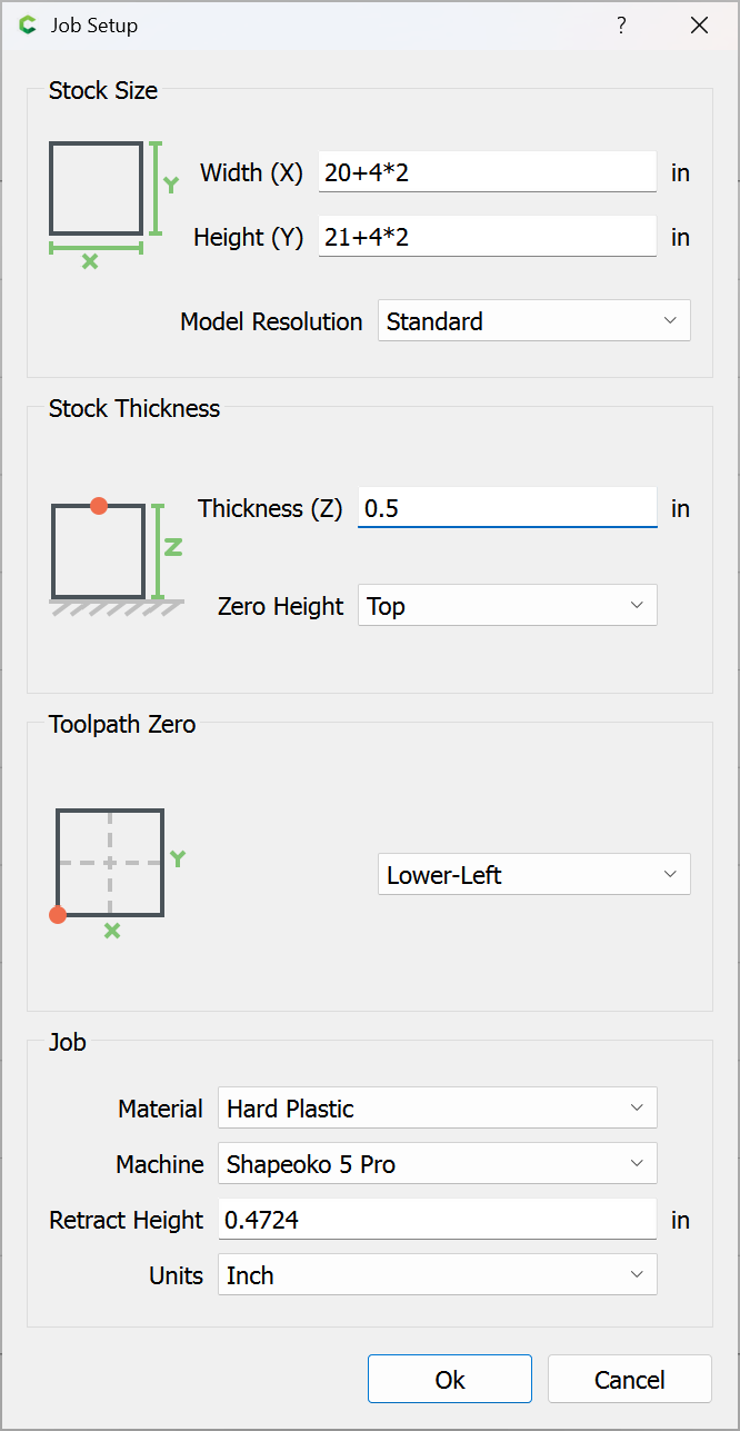
Will be using 1/2 inch plywood with one UV side. Would prefer the finger or box joints to be hidden when the boxes are joined together. Average size would be 4” H x 21” D c 20” W. And I’d hope to be able to adjust the layout myself for different sizing.
I do want to learn and hope this might be a good start.
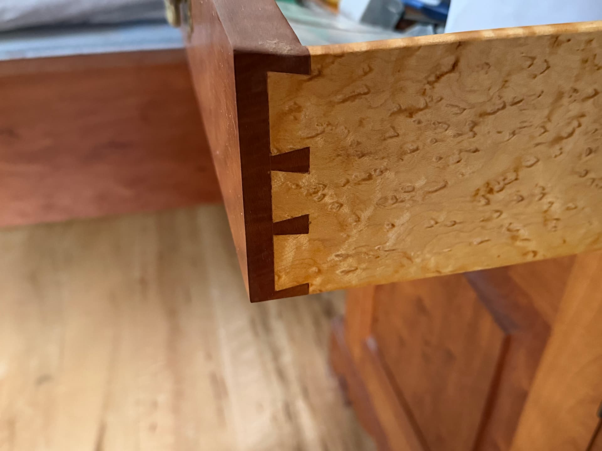
I’ve done traditional box joints using a vertical fixture before:
but doing things thus has some notable cons:
minimum of three setups: 1 - cut to size and machine internal features, 2 - mount all 4 boards and cut two corners worth of joints, 3 - rotate all 4 boards and cut other two corners
possibility of orienting boards wrong when cutting joints
exposed grain makes getting the positioning/Z-axis zero setting critical
width/depth limited by height of table which the machine is on
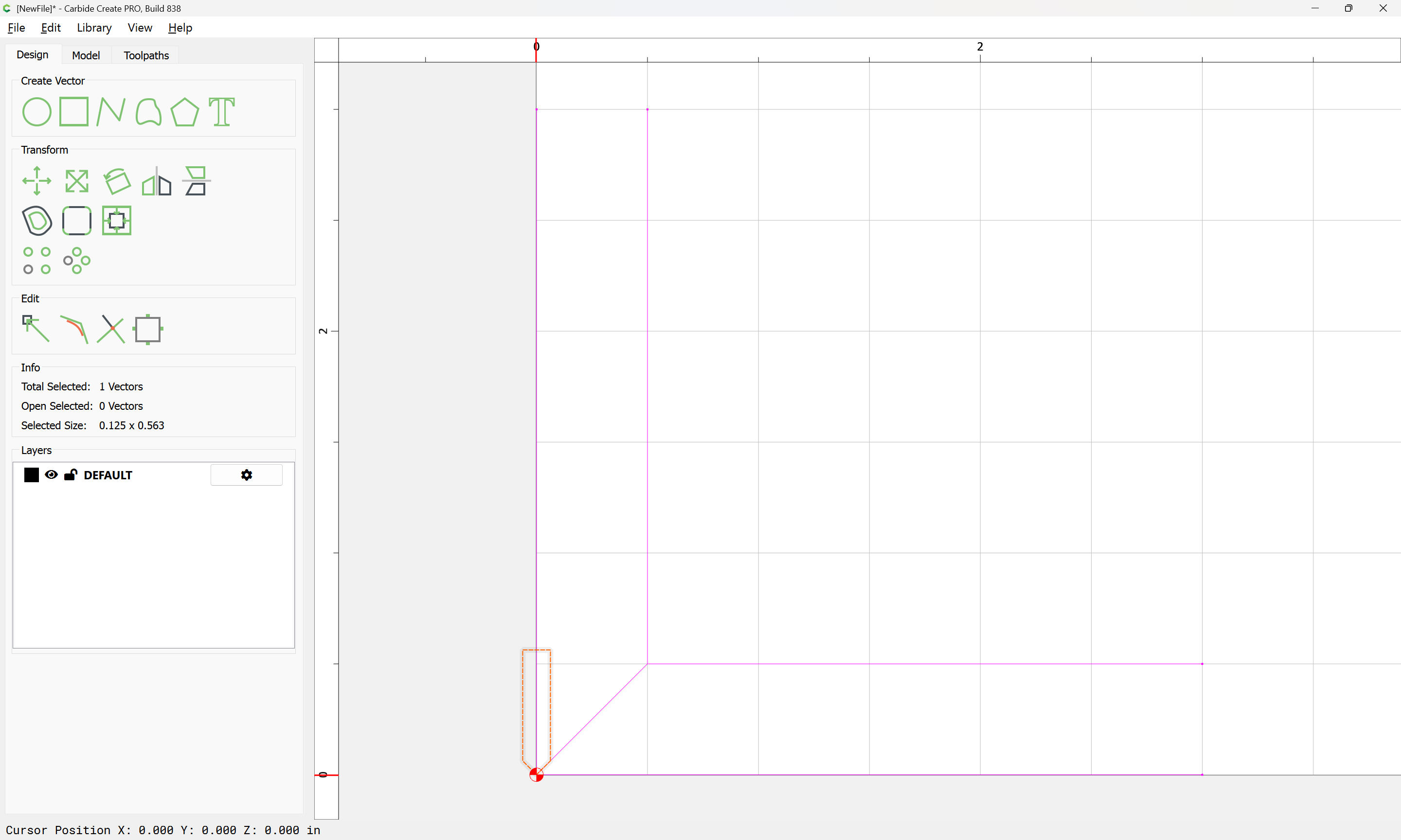
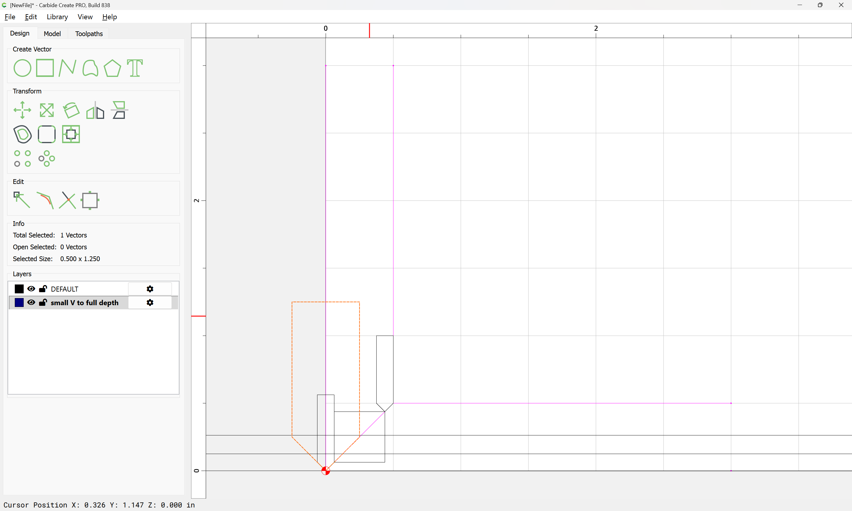
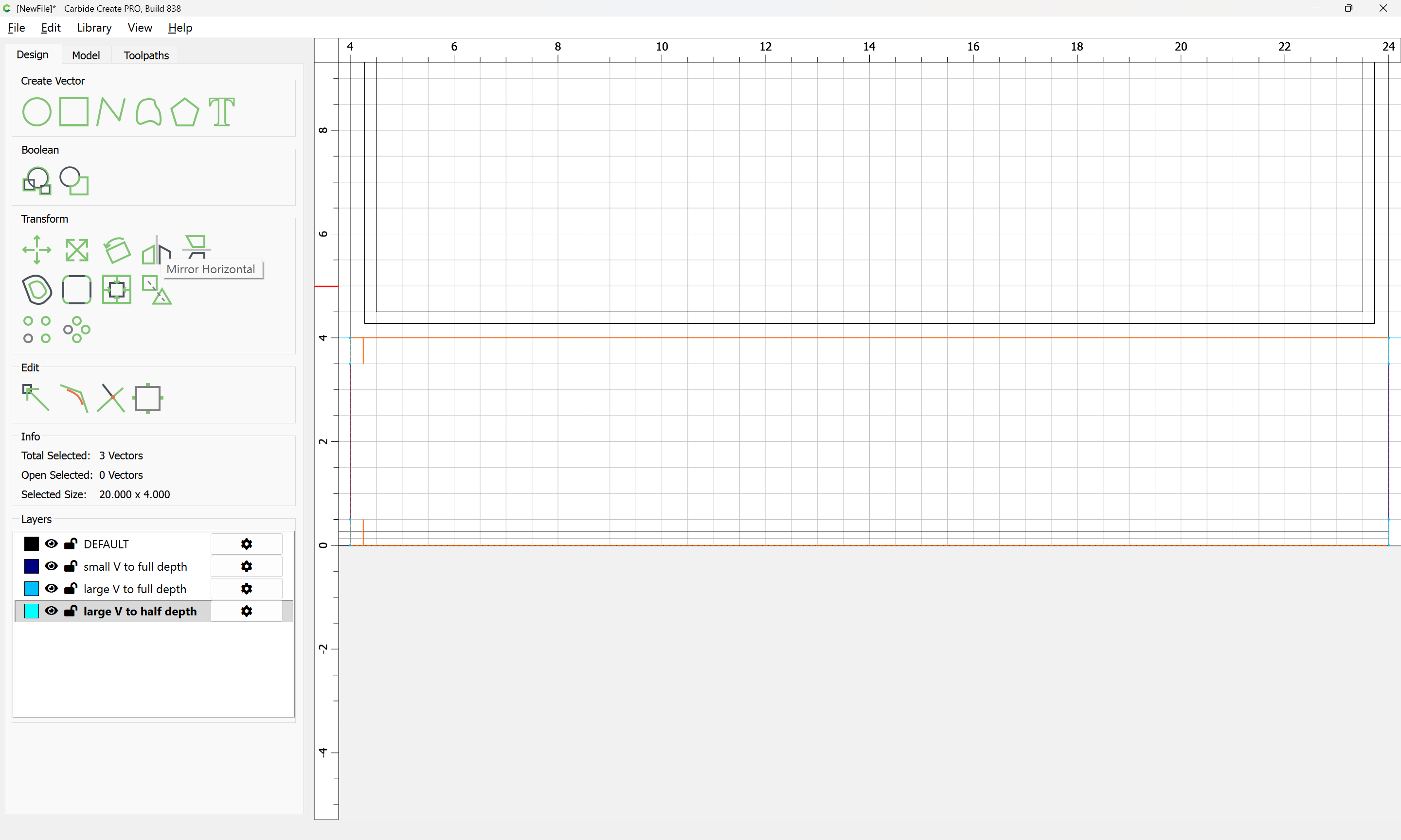
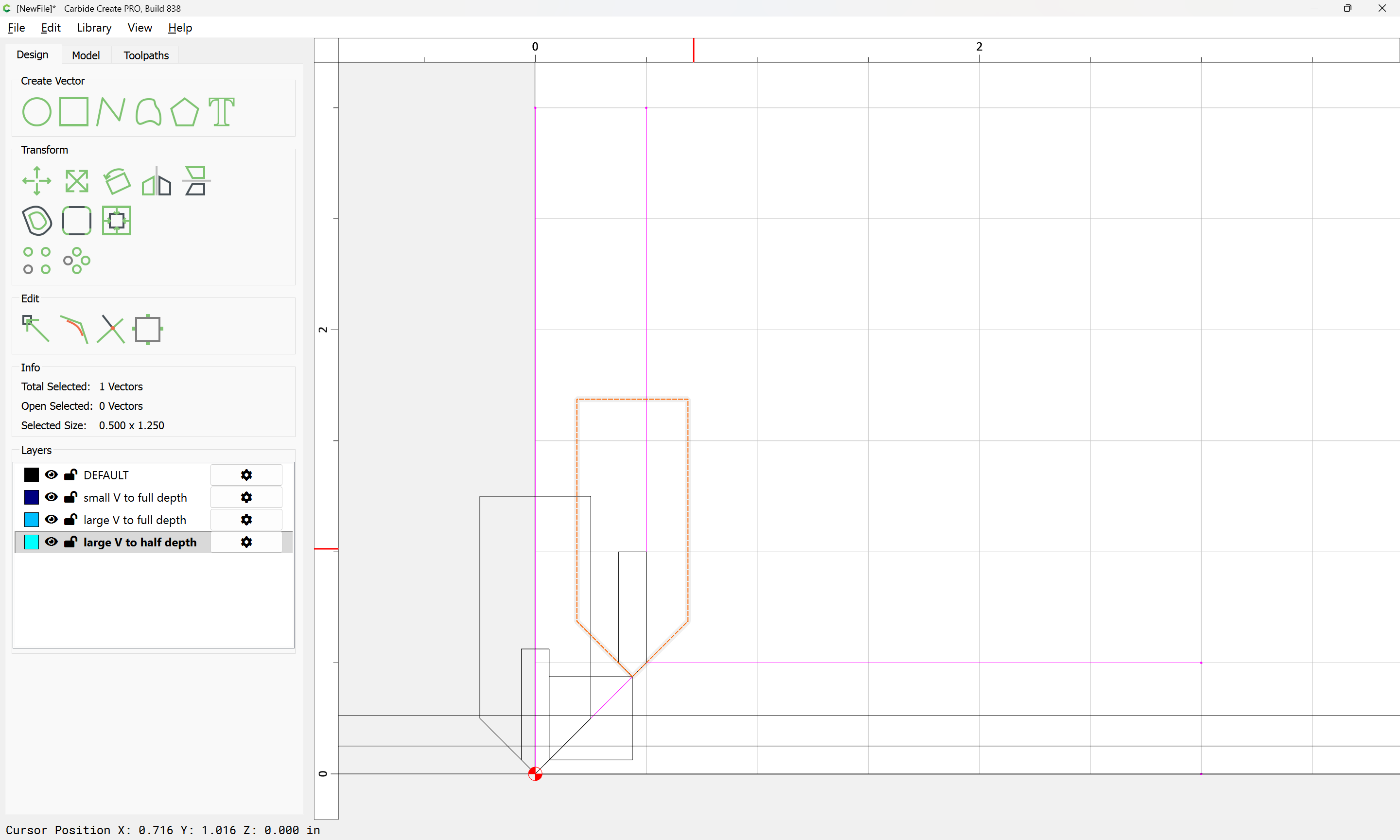
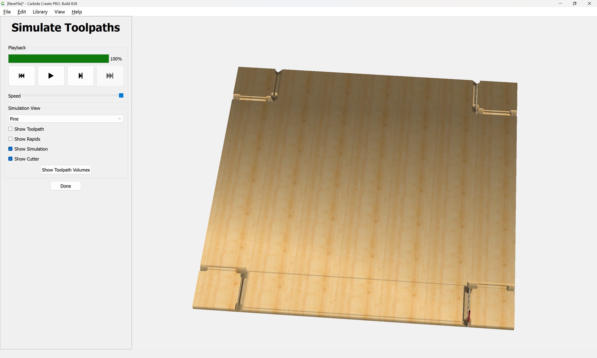
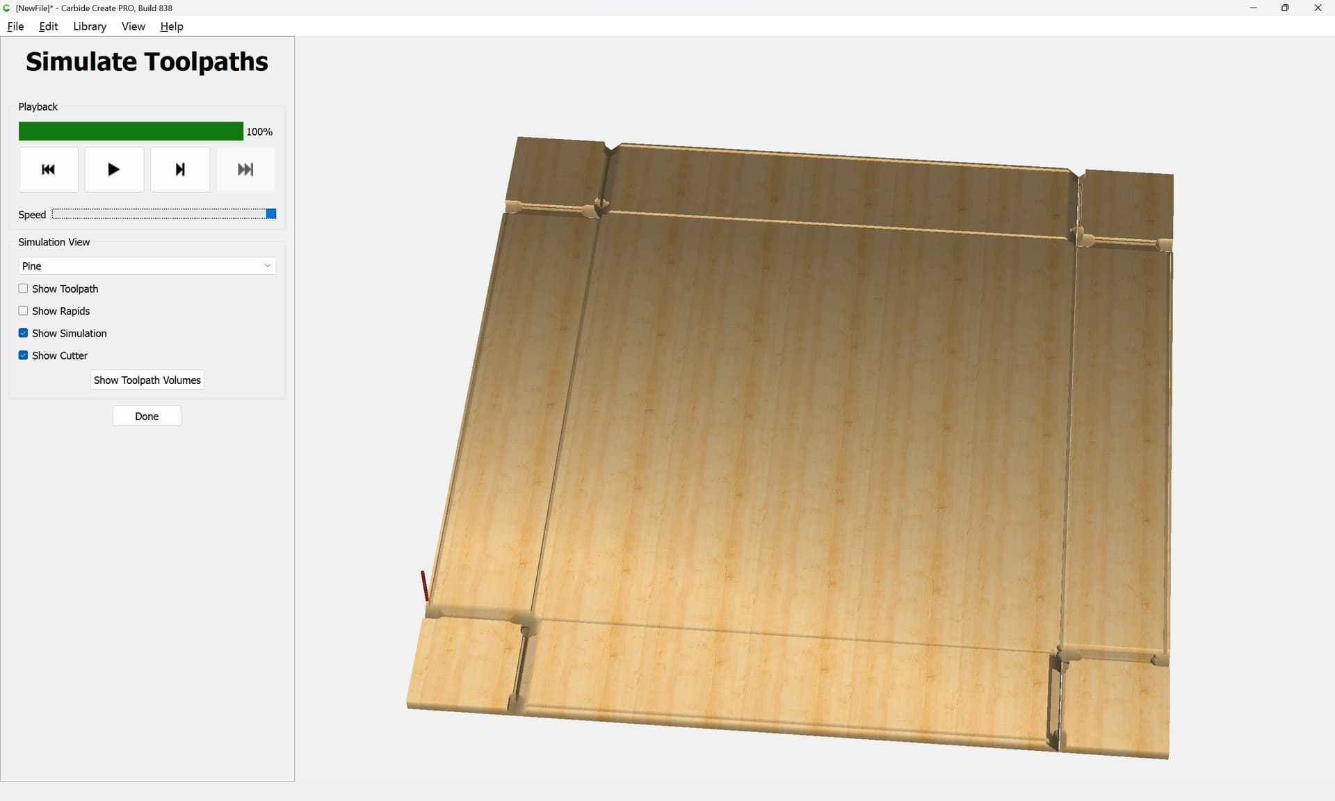
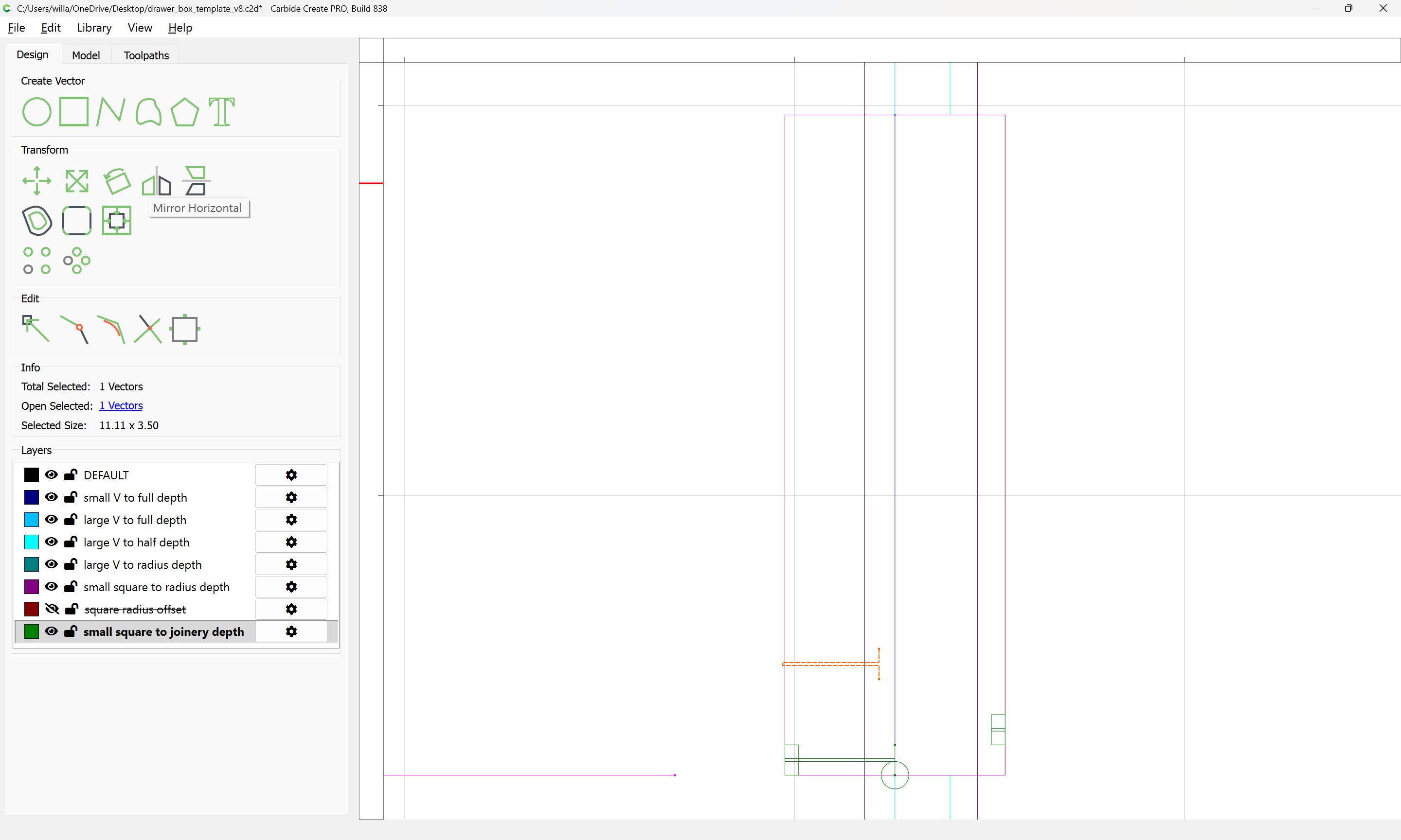
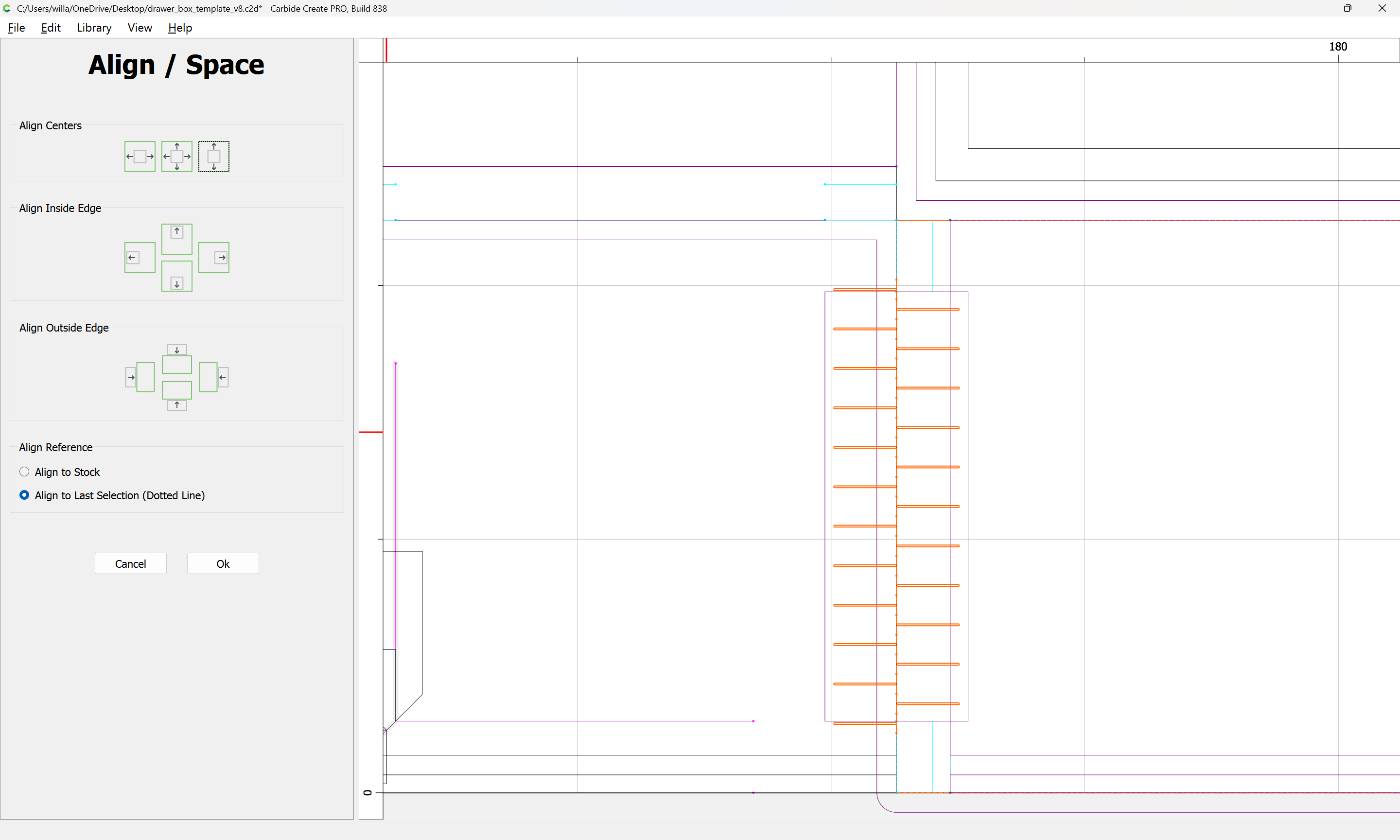
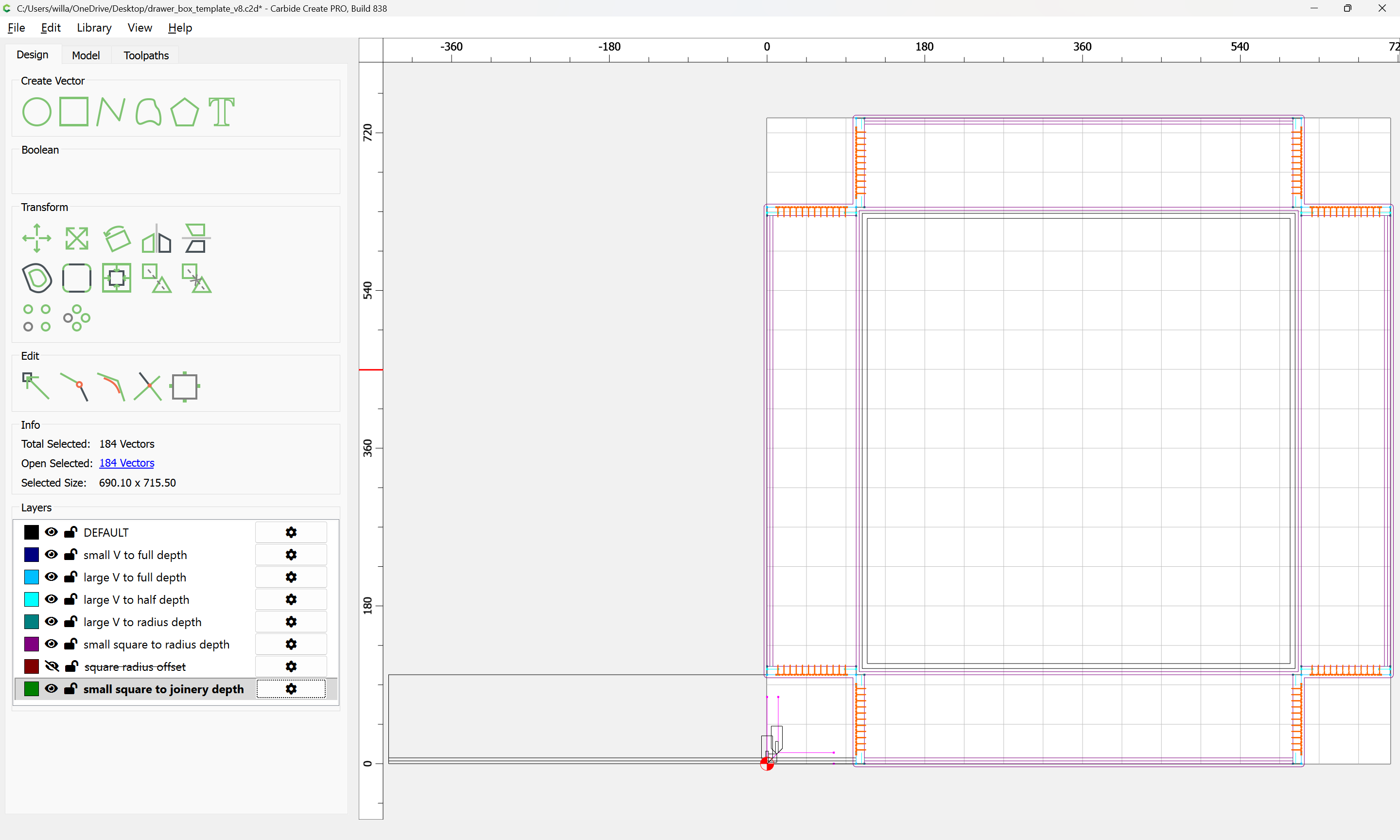
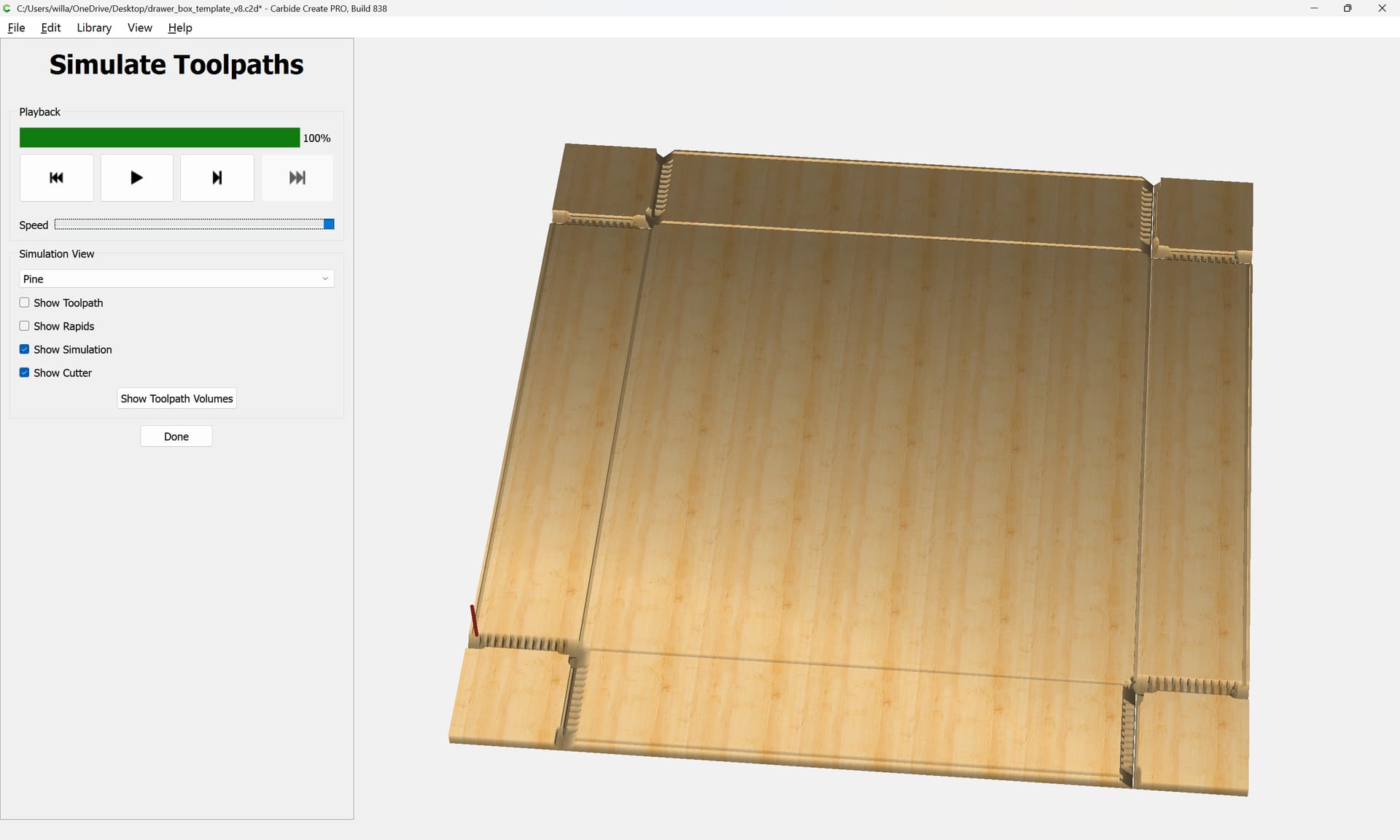
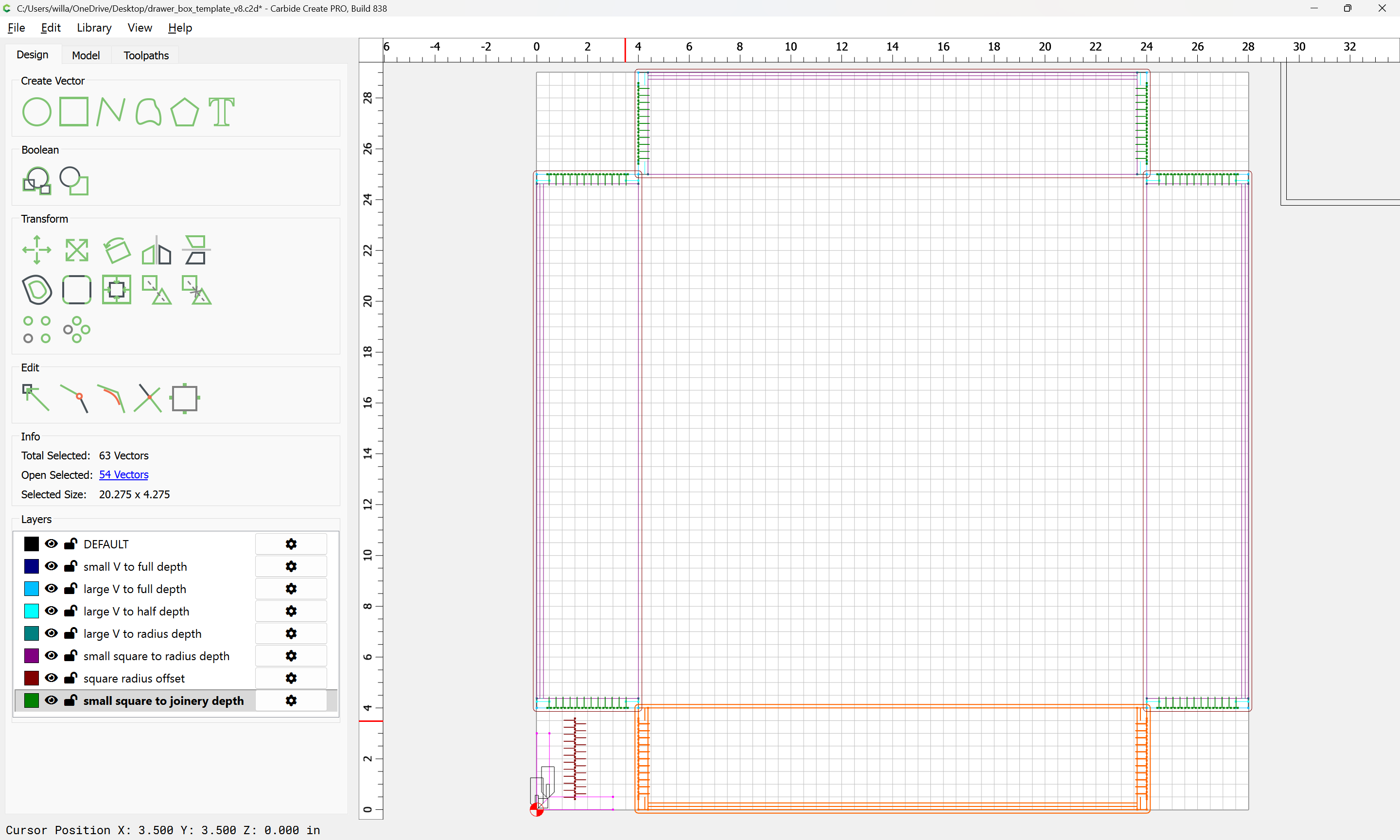
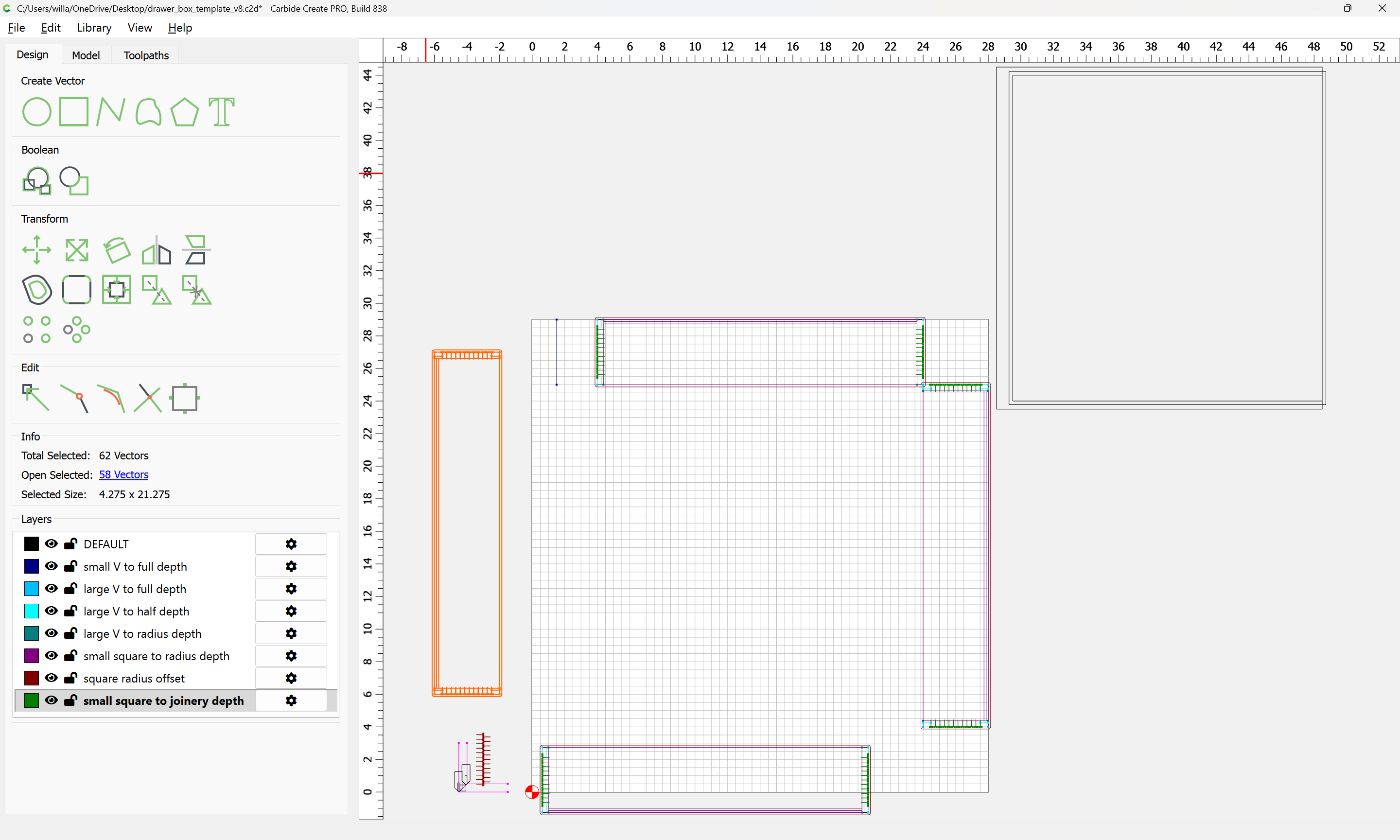
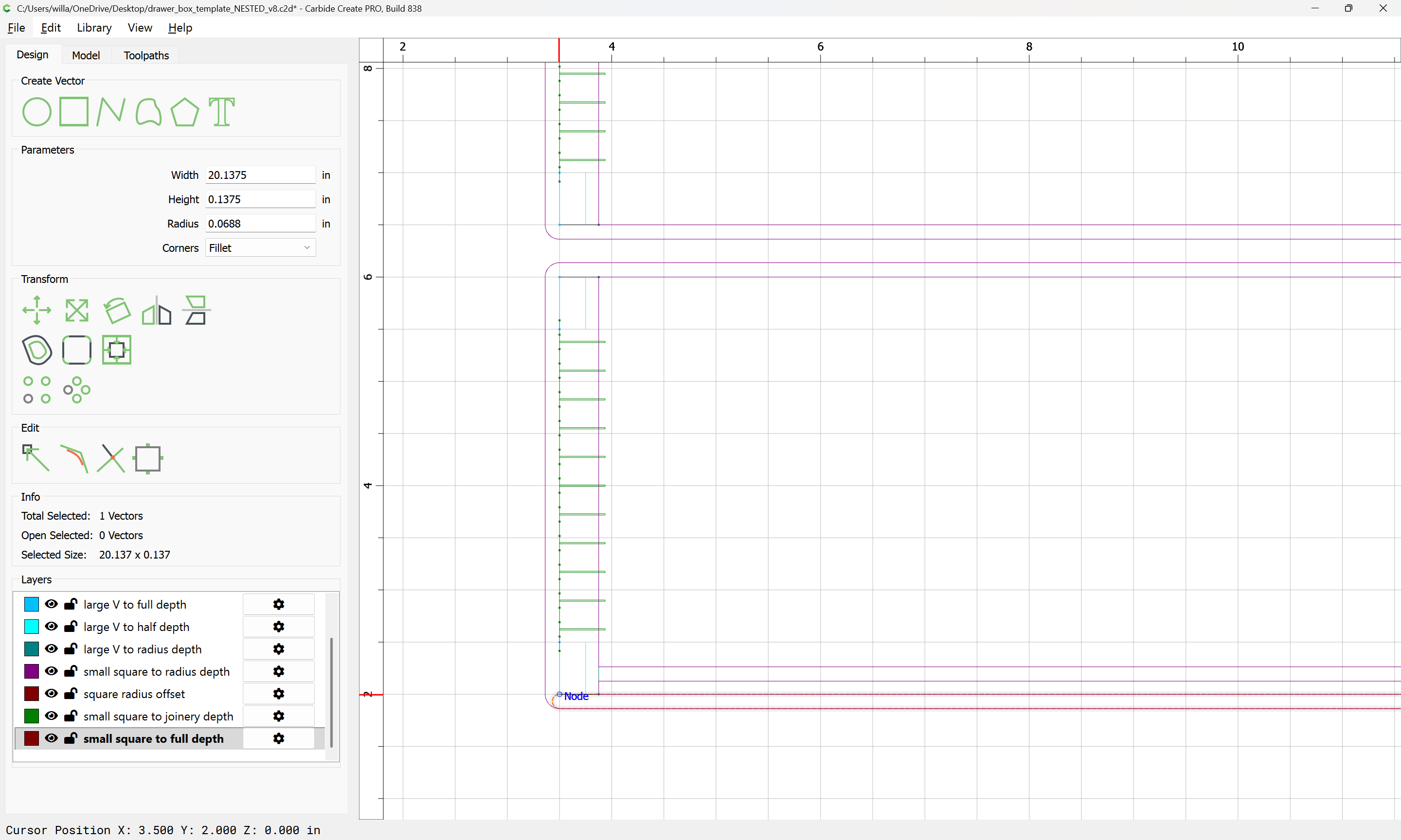
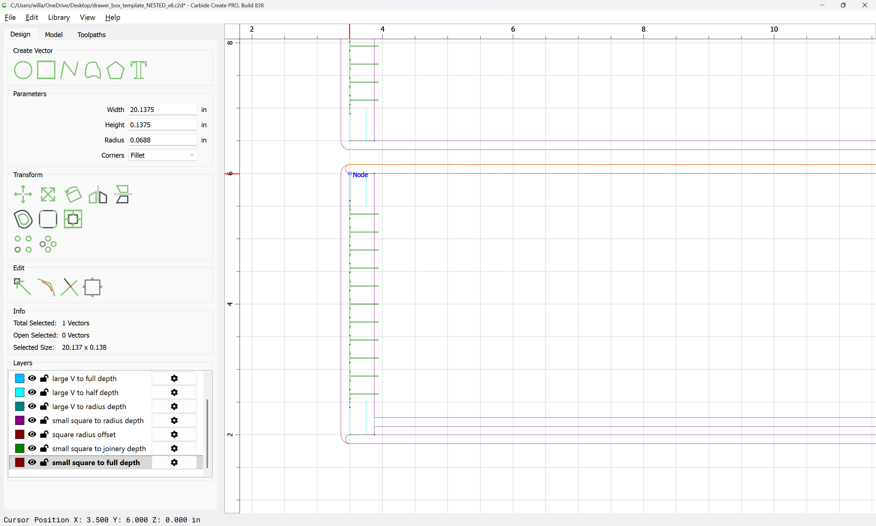
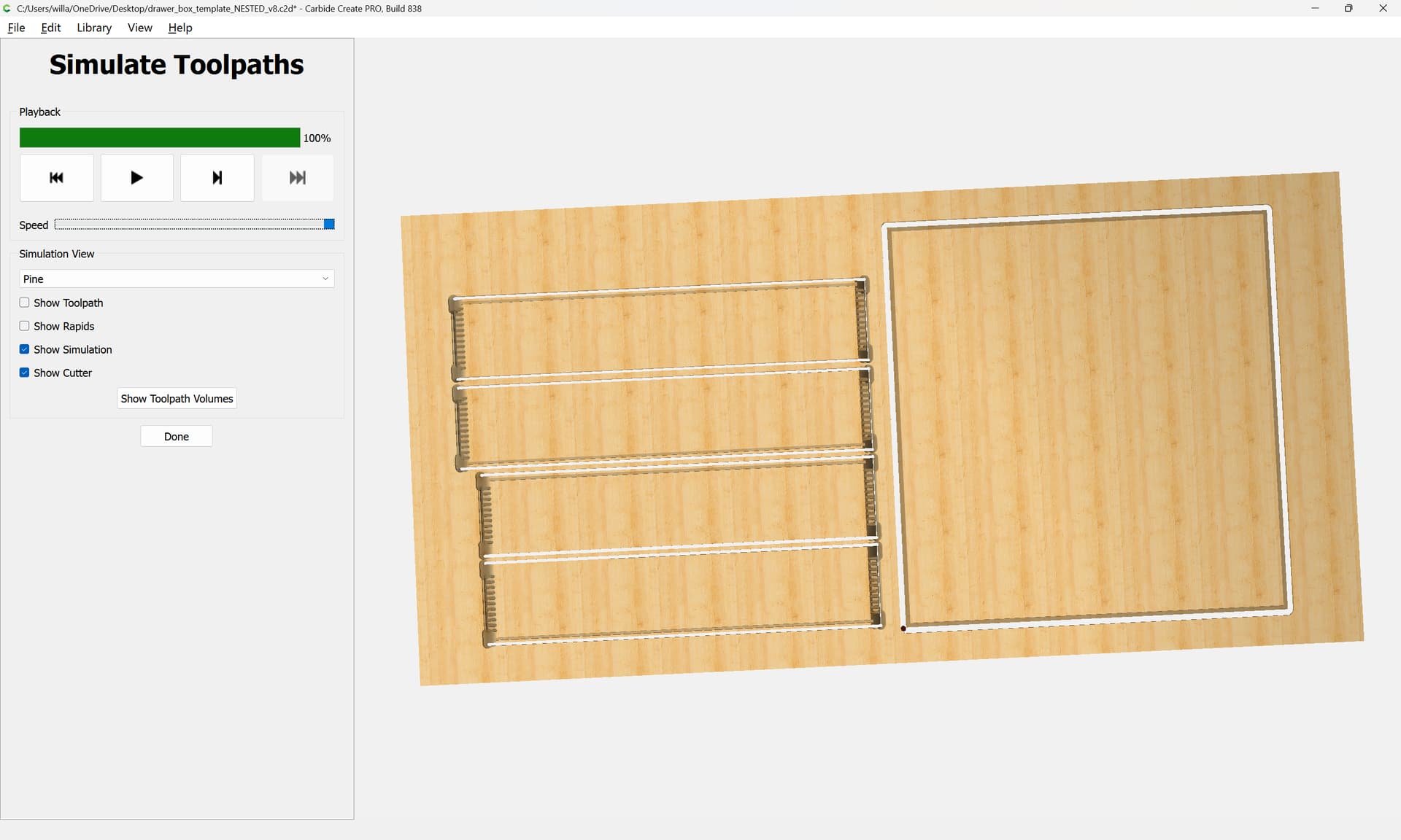
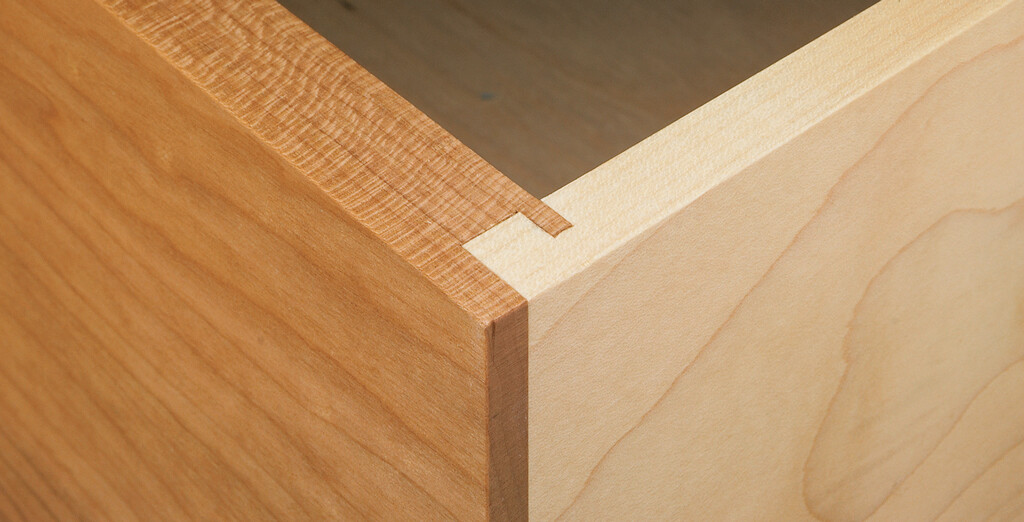
My recommendation would be for full-blind hidden box joints instead:
which allows cutting the entirety of the design with a single setup — one negative is that it requires a small/narrow 90 degree V tool and a matching (or slightly smaller) square tool, and this further means that the time spent machining is increased by the use of the small tools.
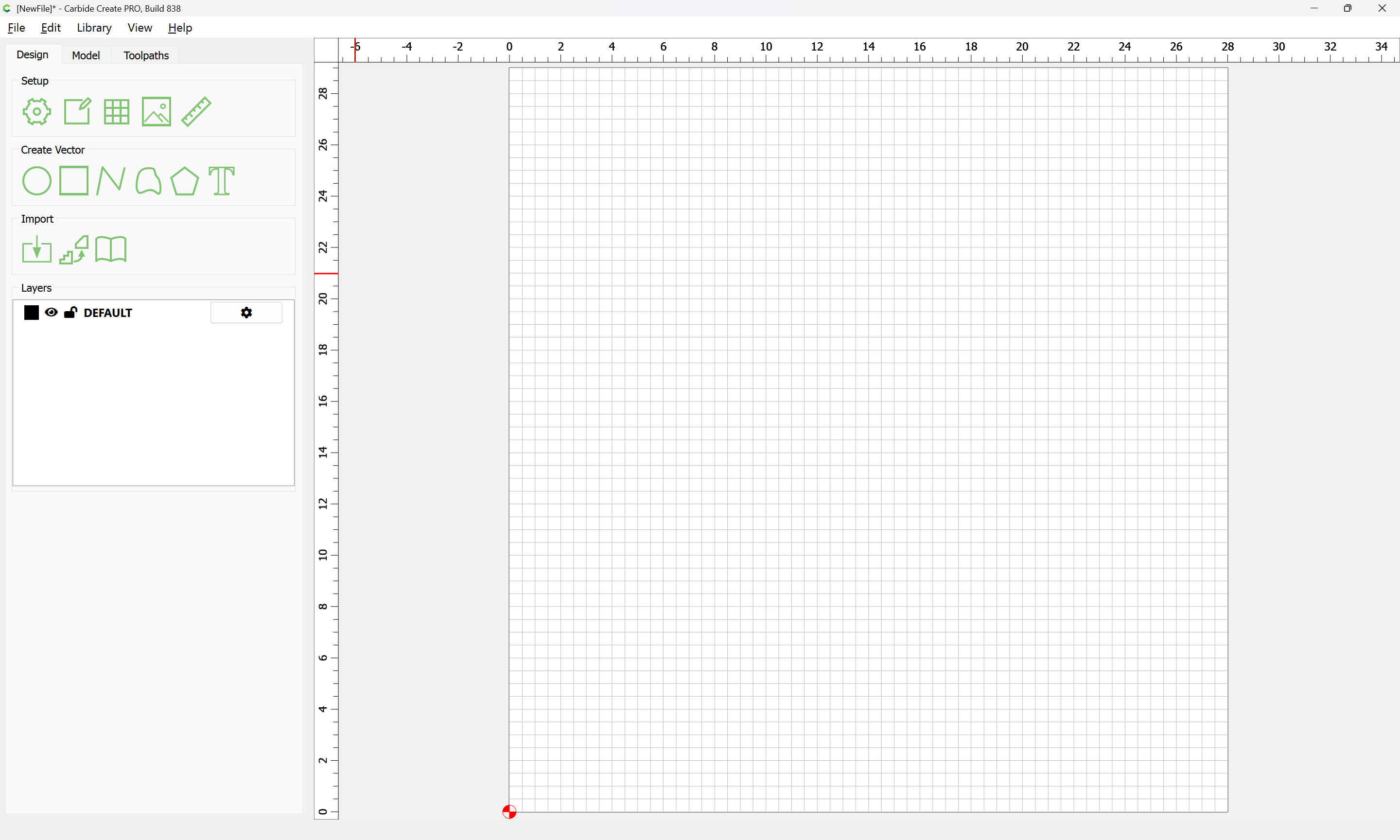
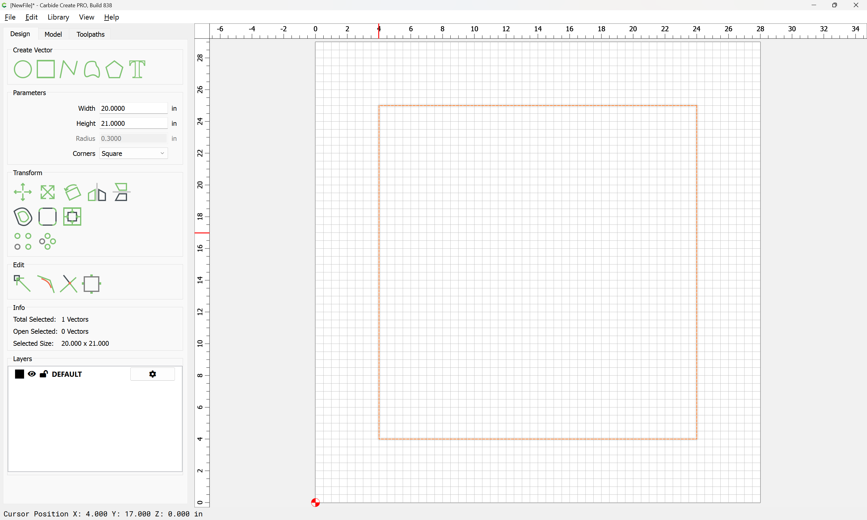
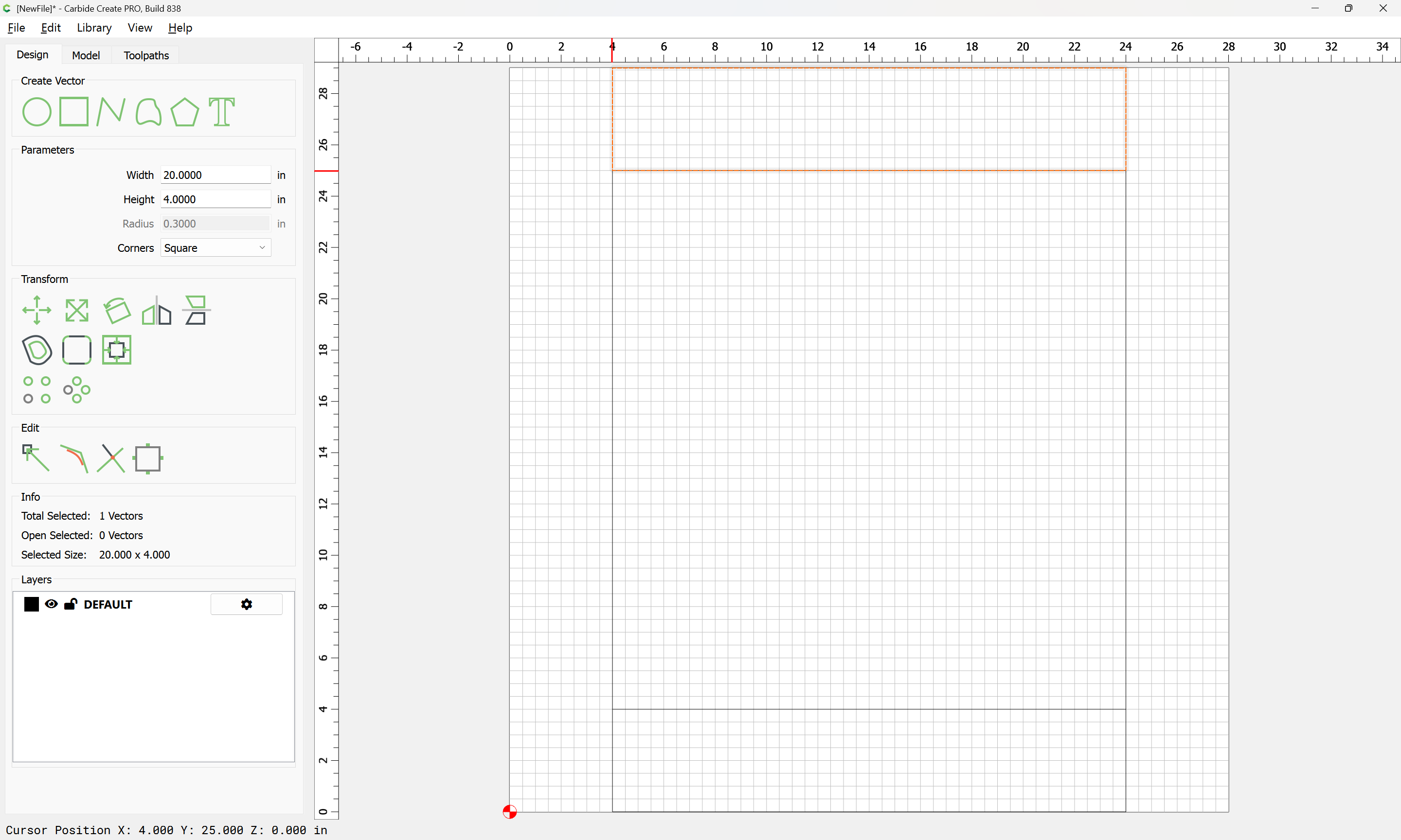
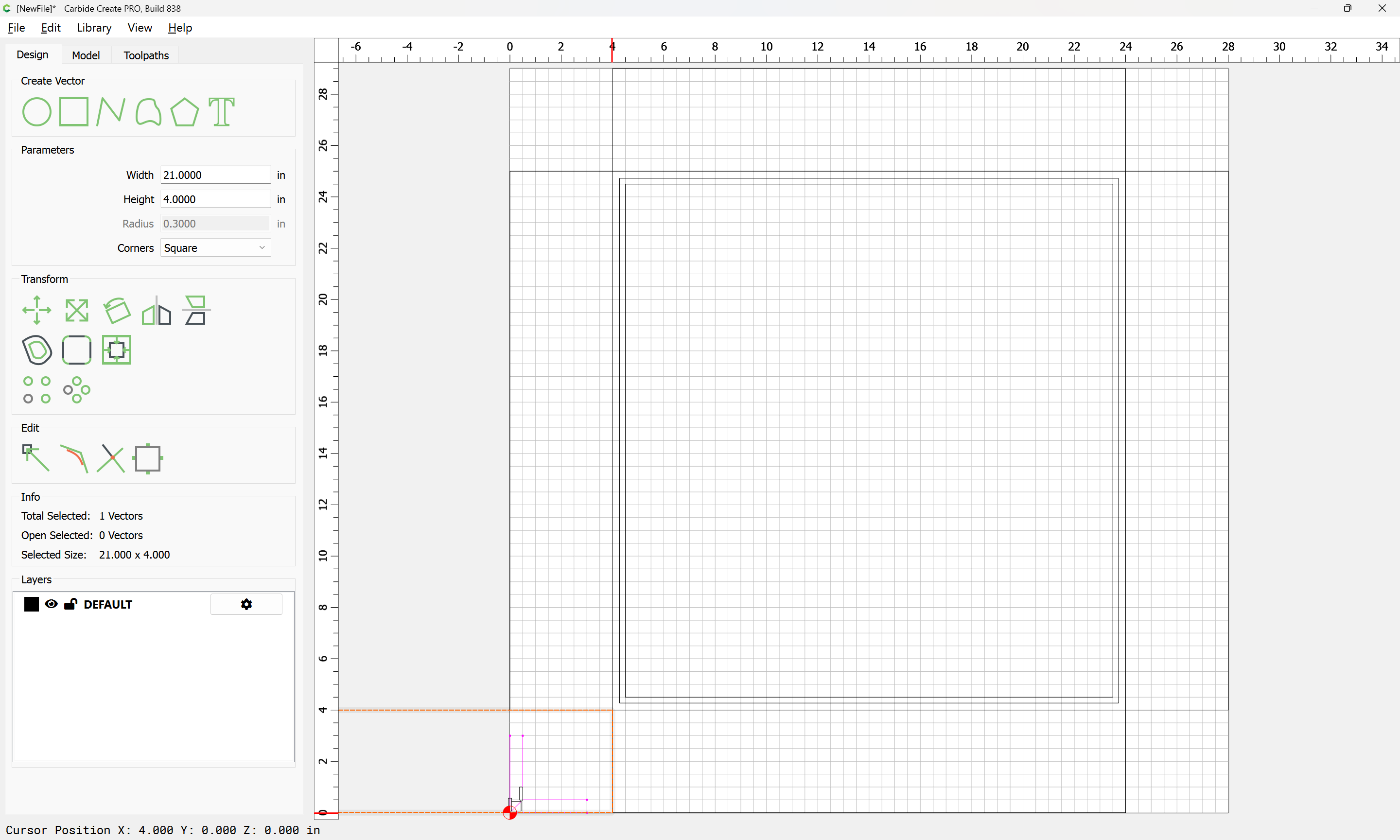
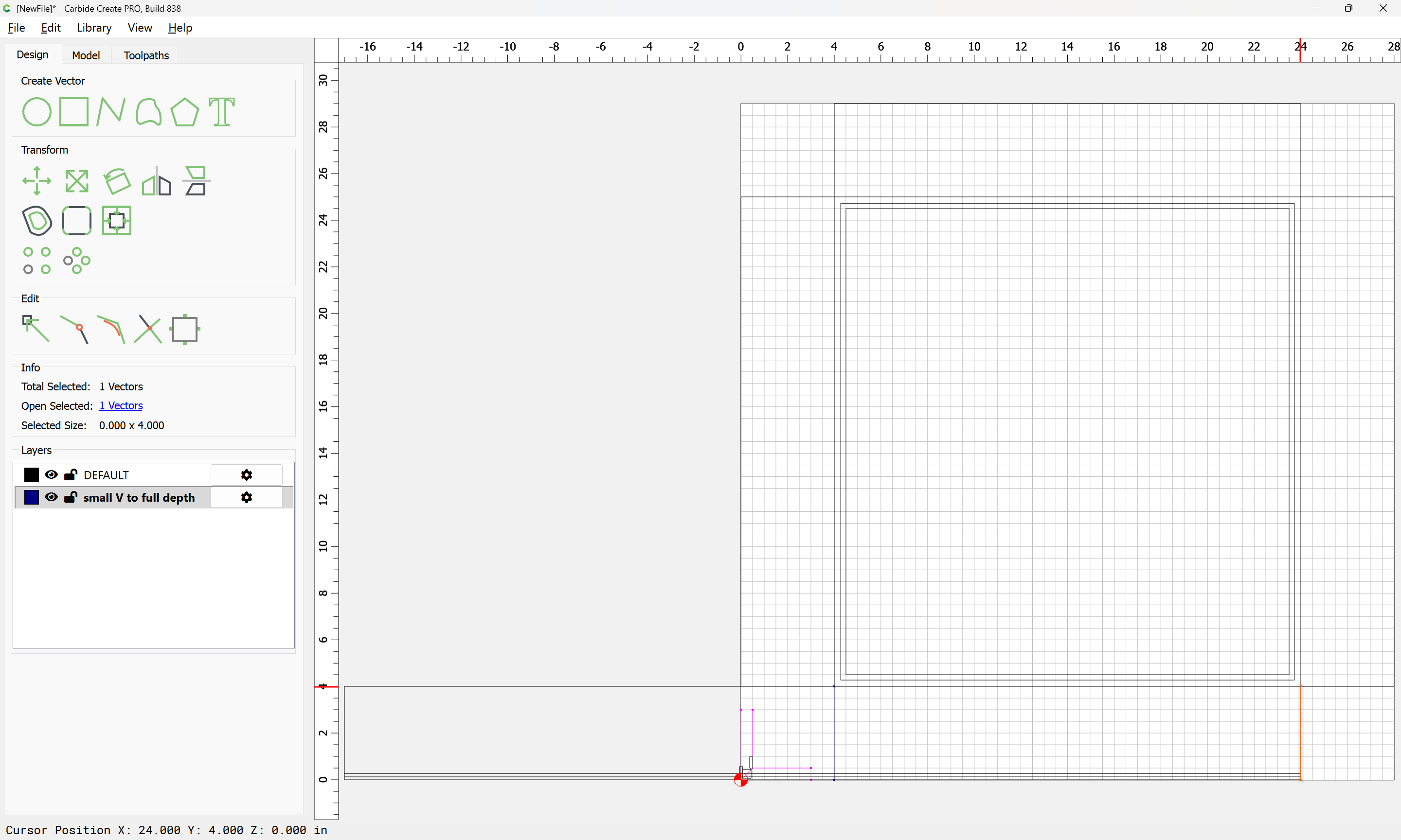
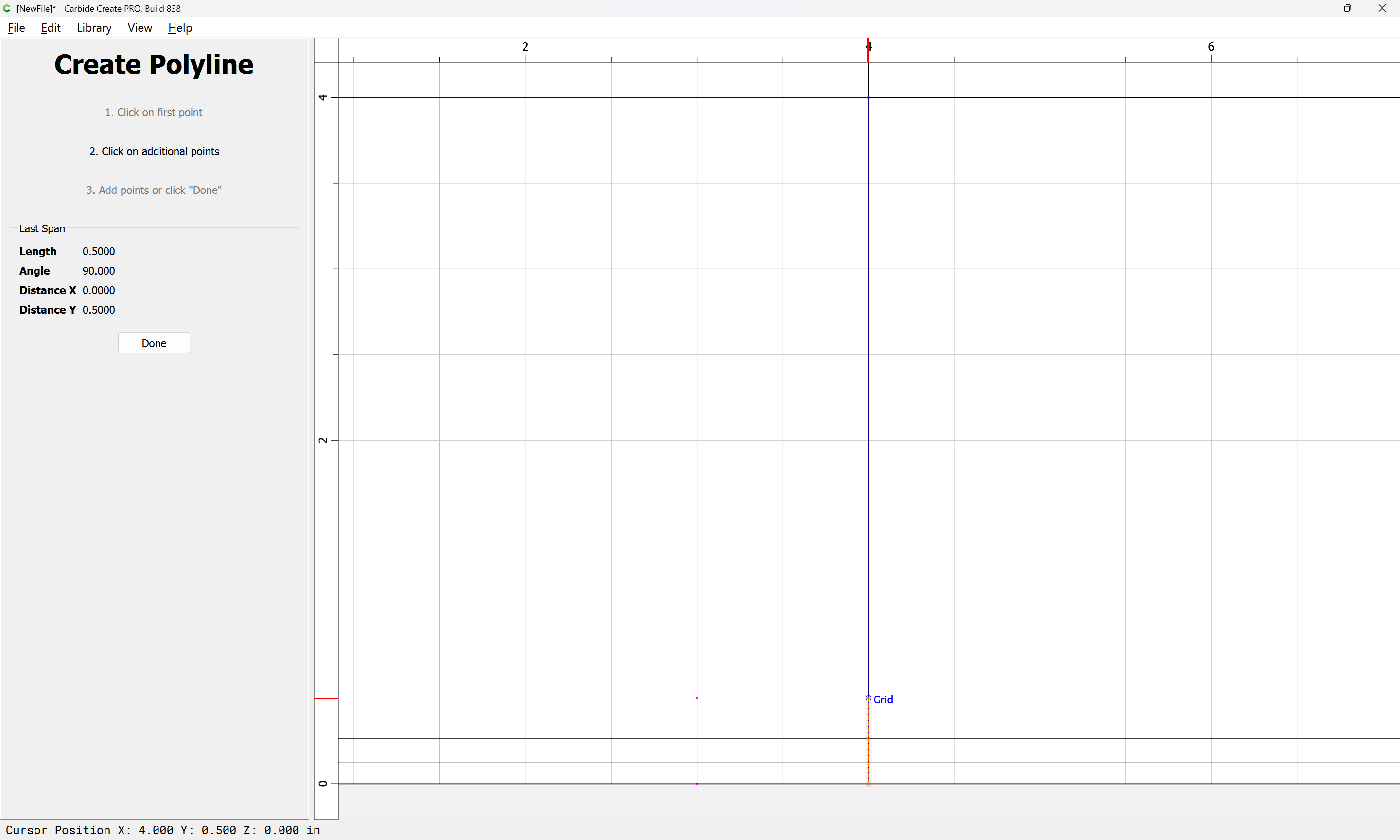
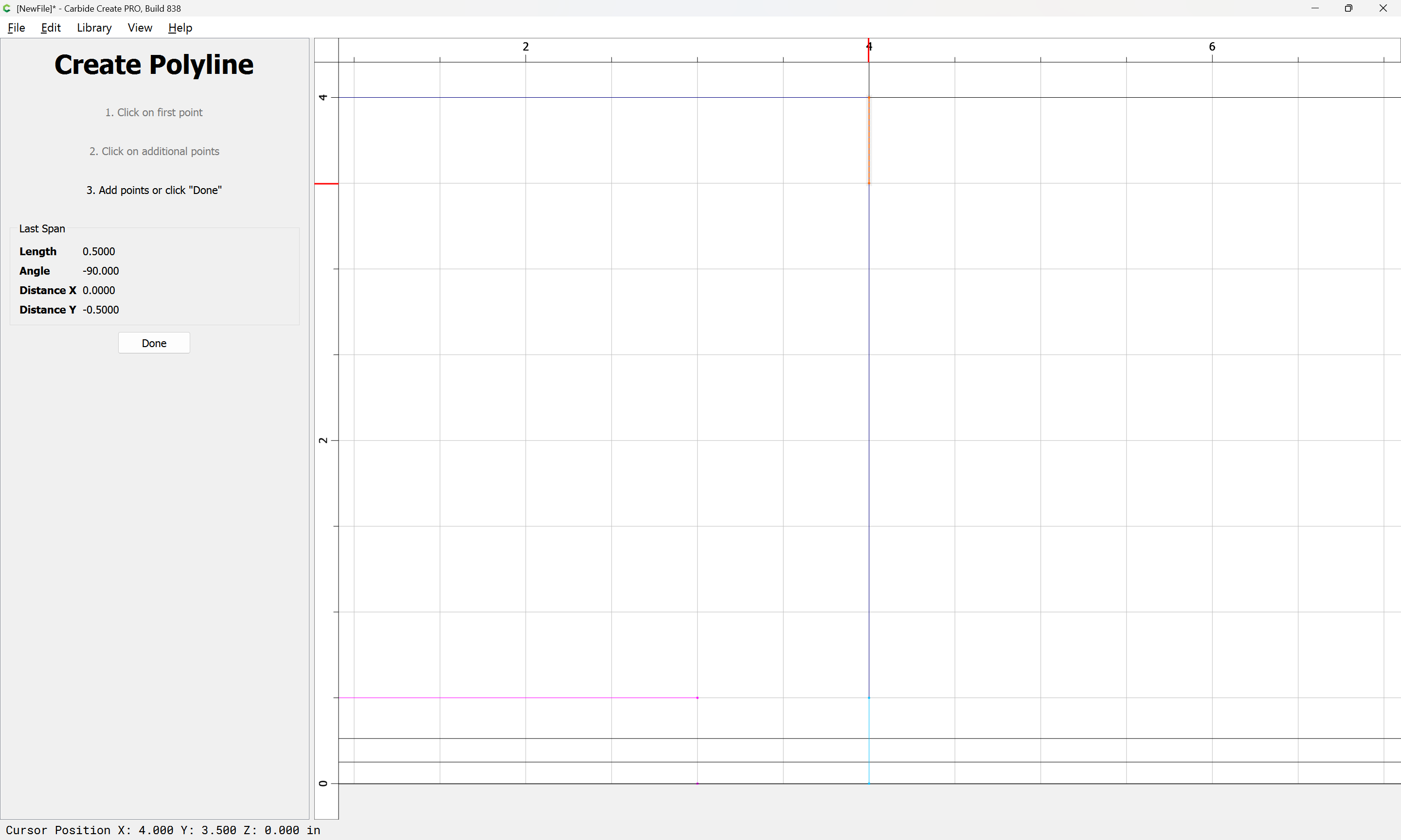
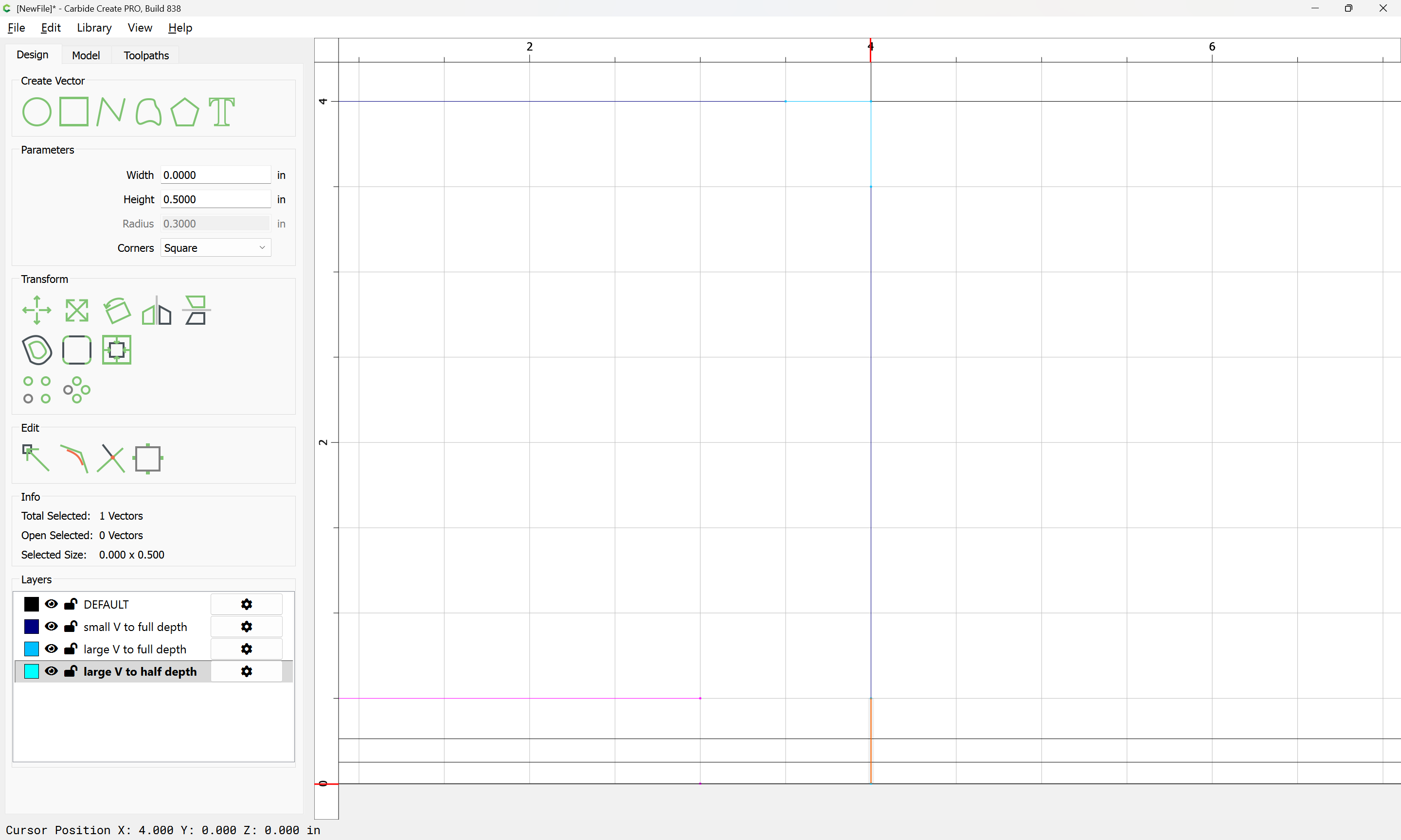
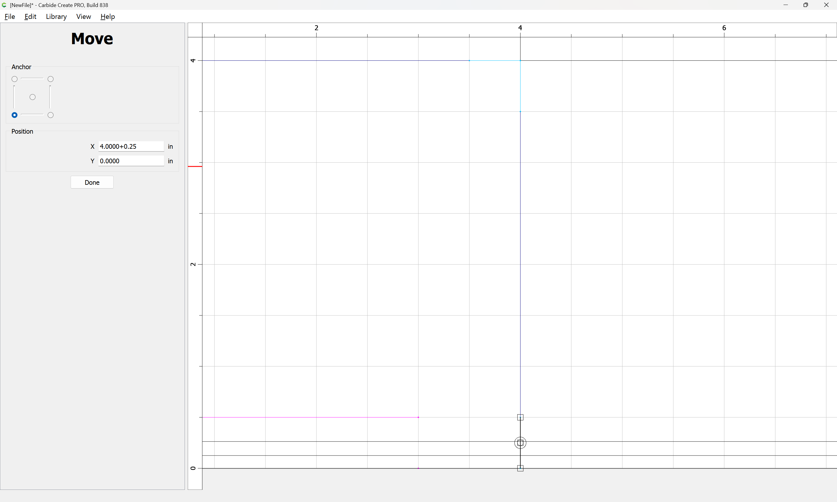
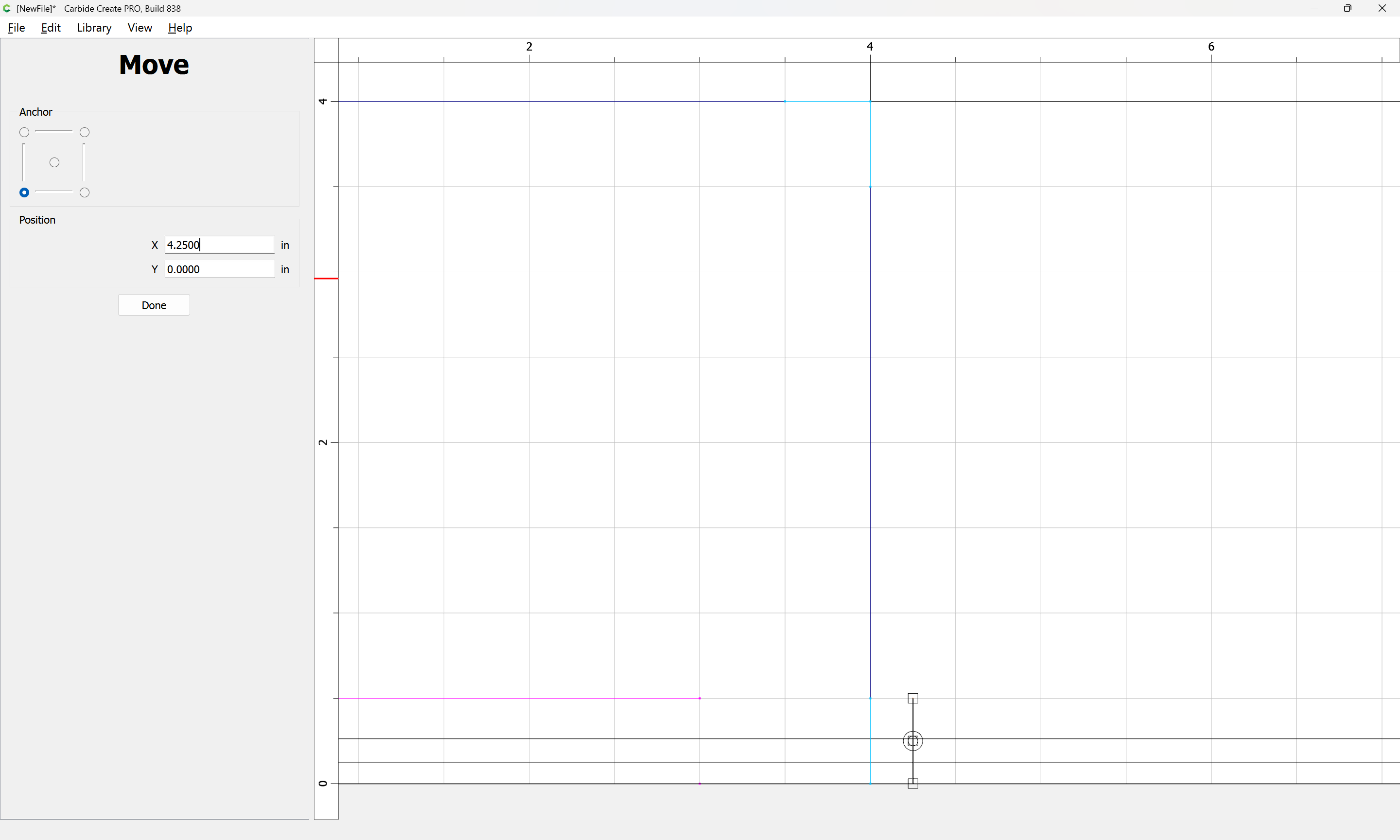
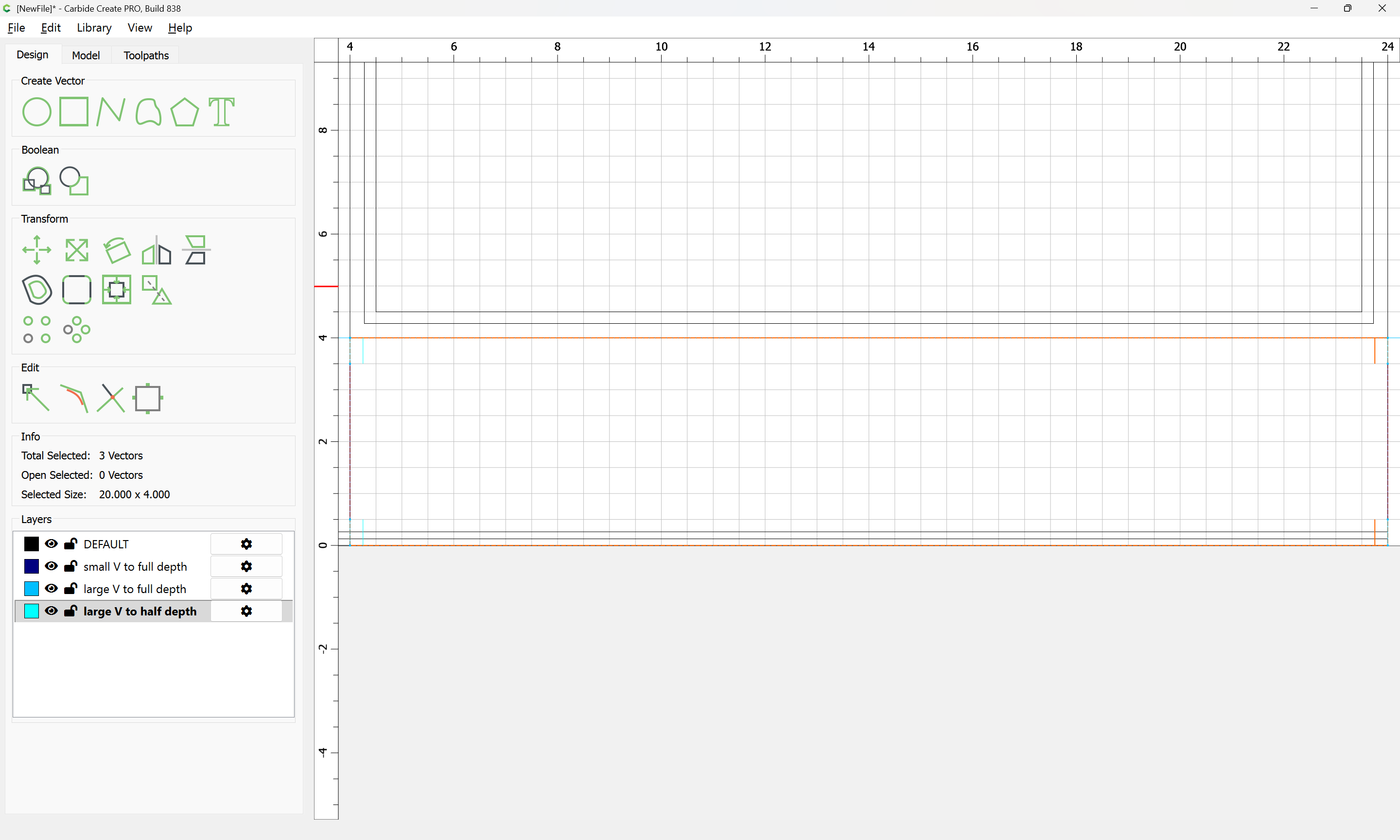
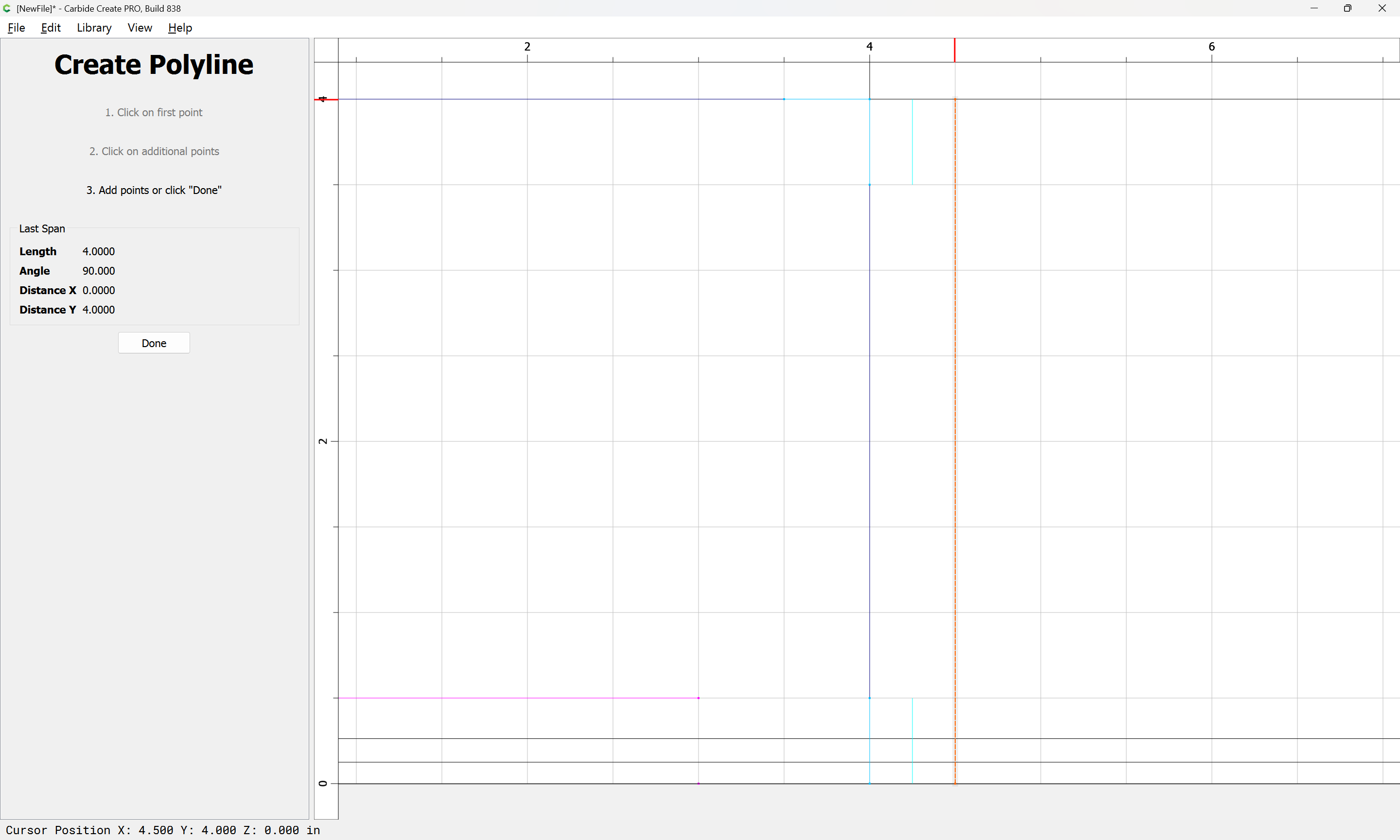
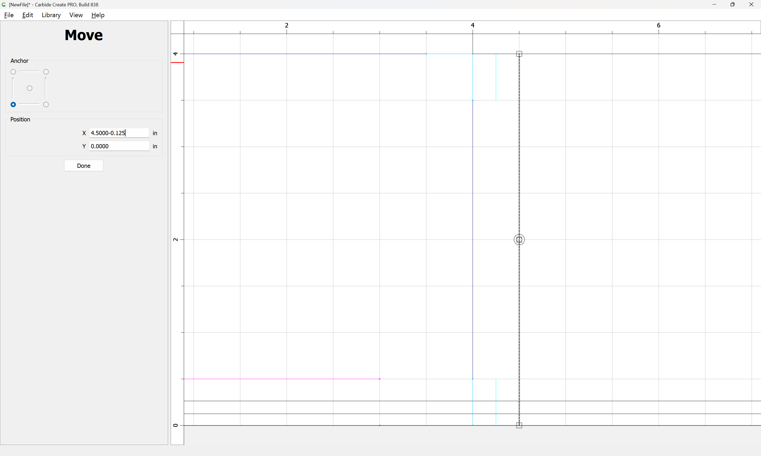
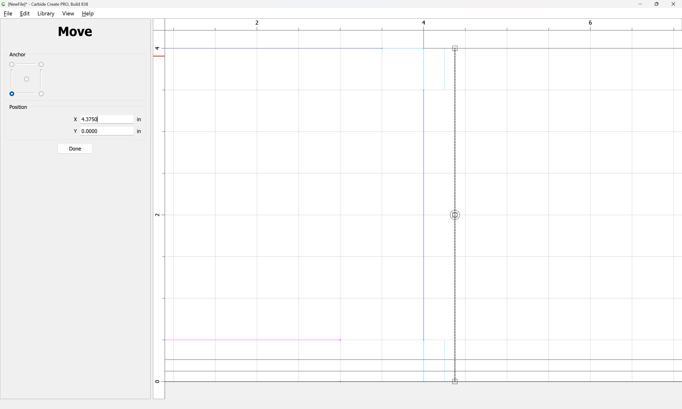
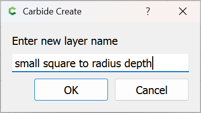
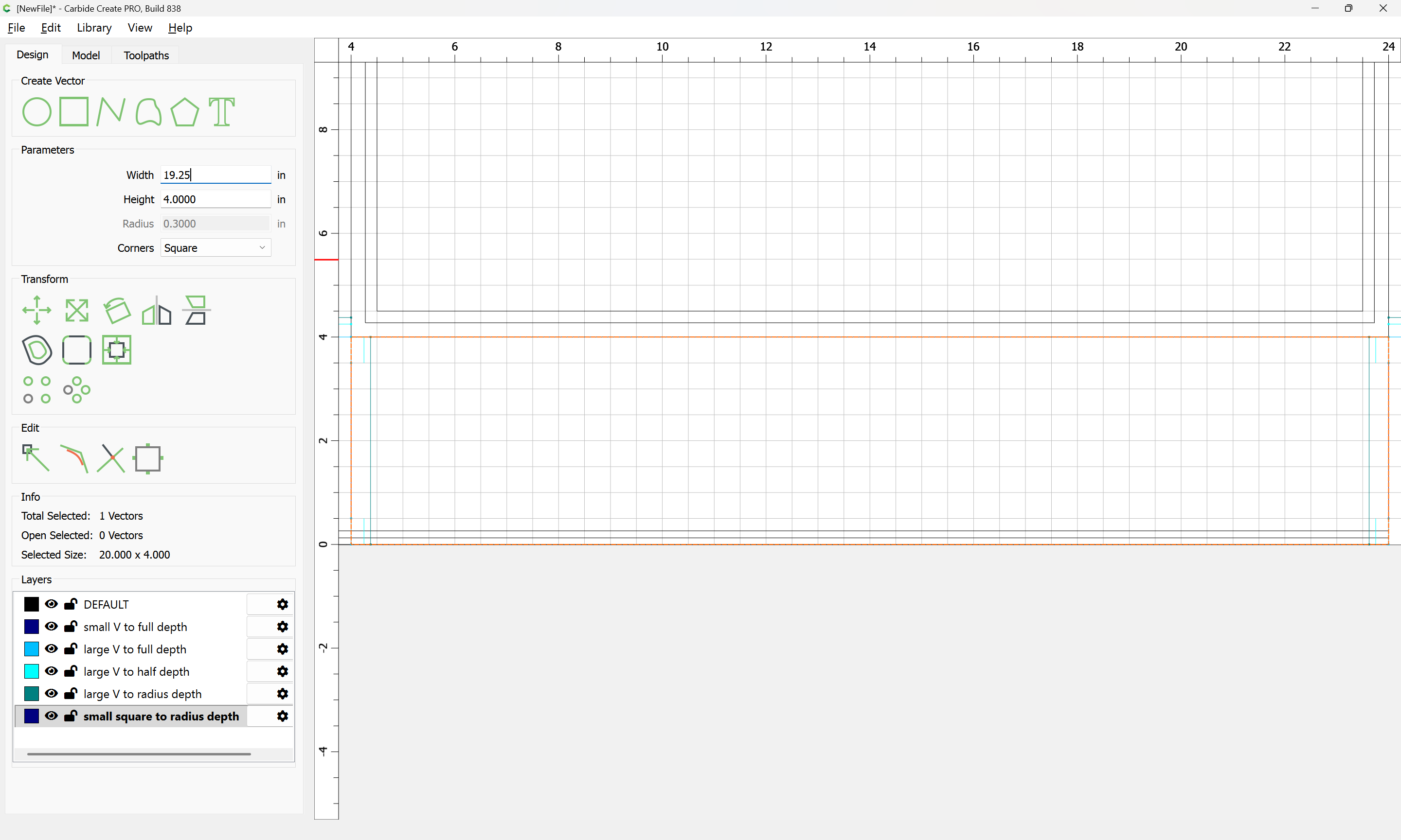
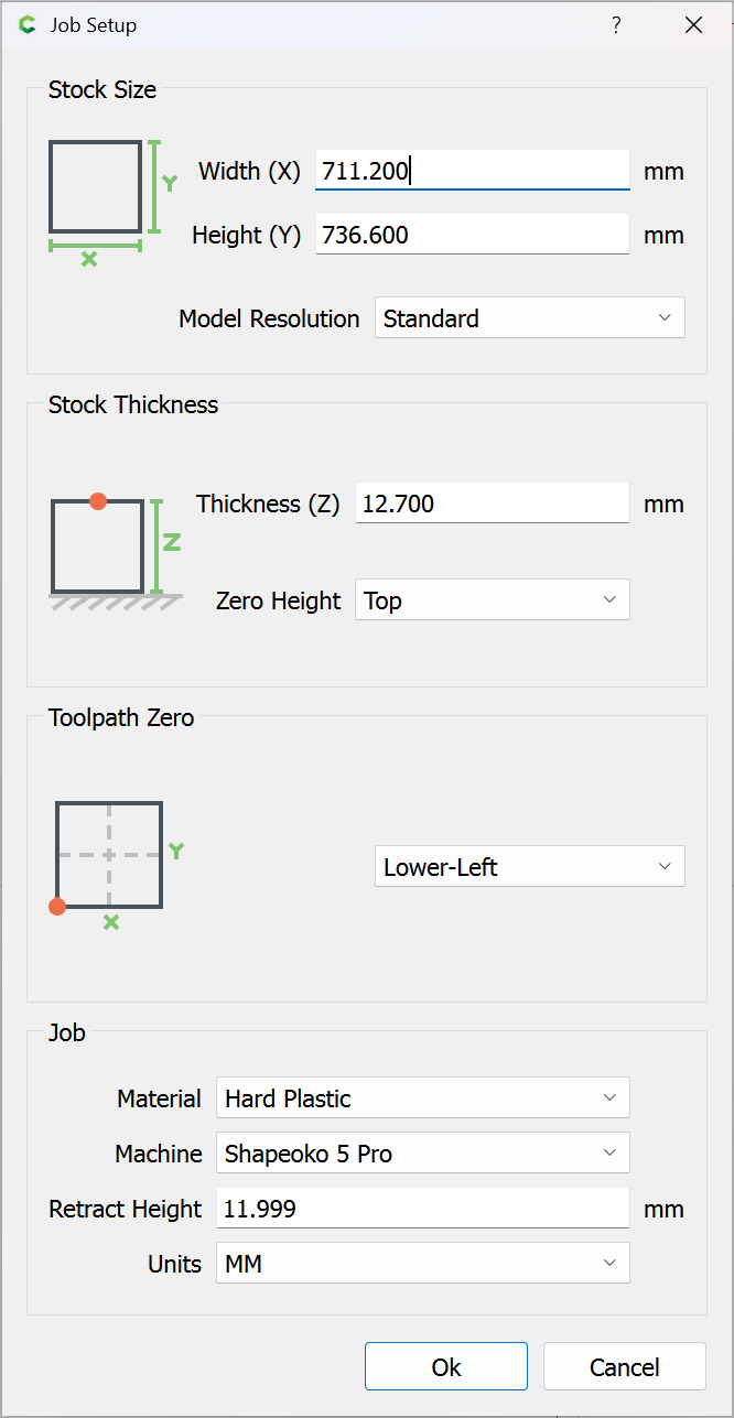
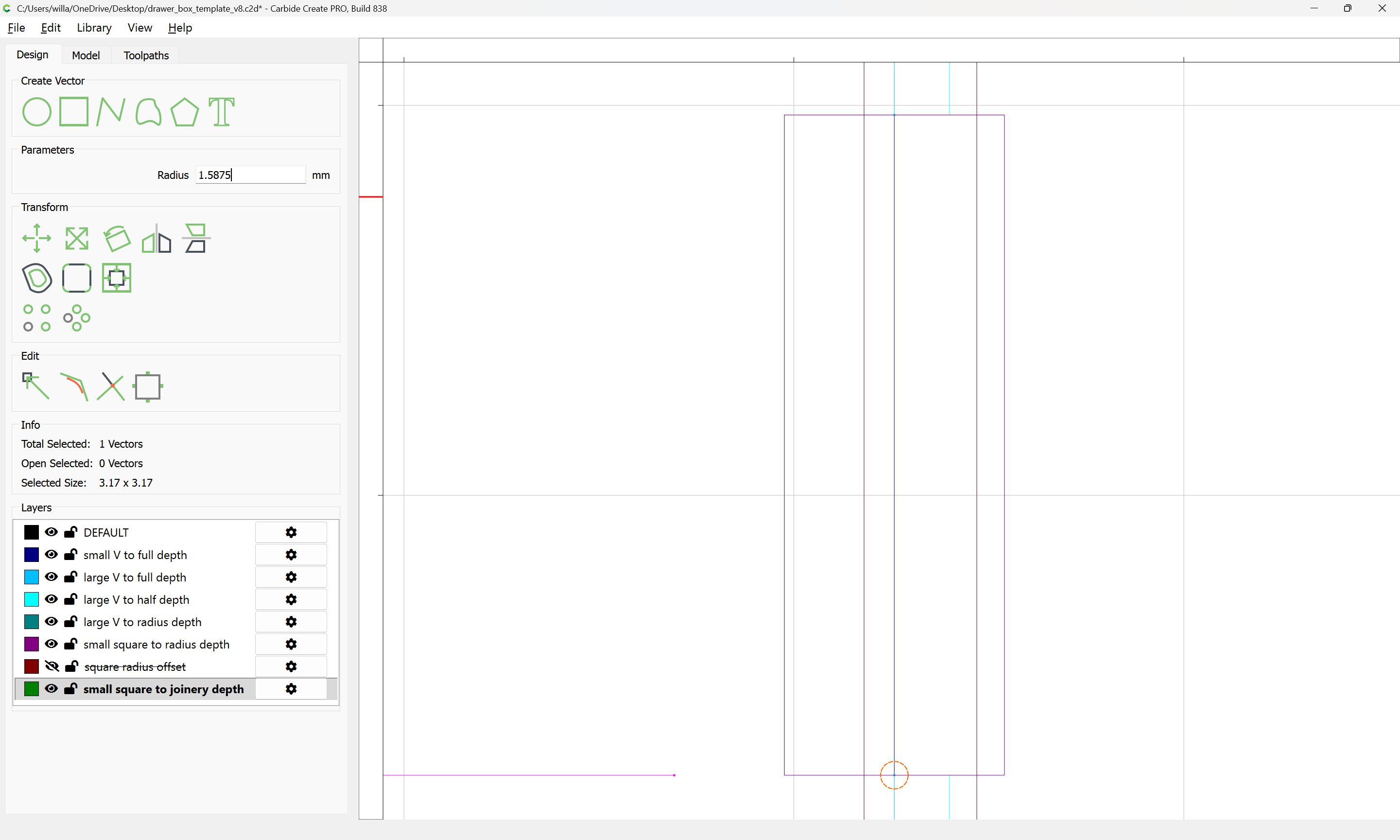
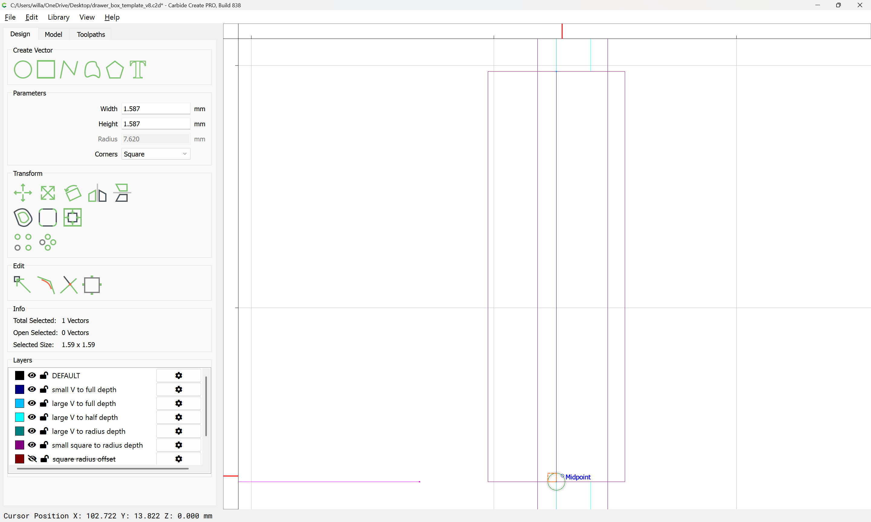
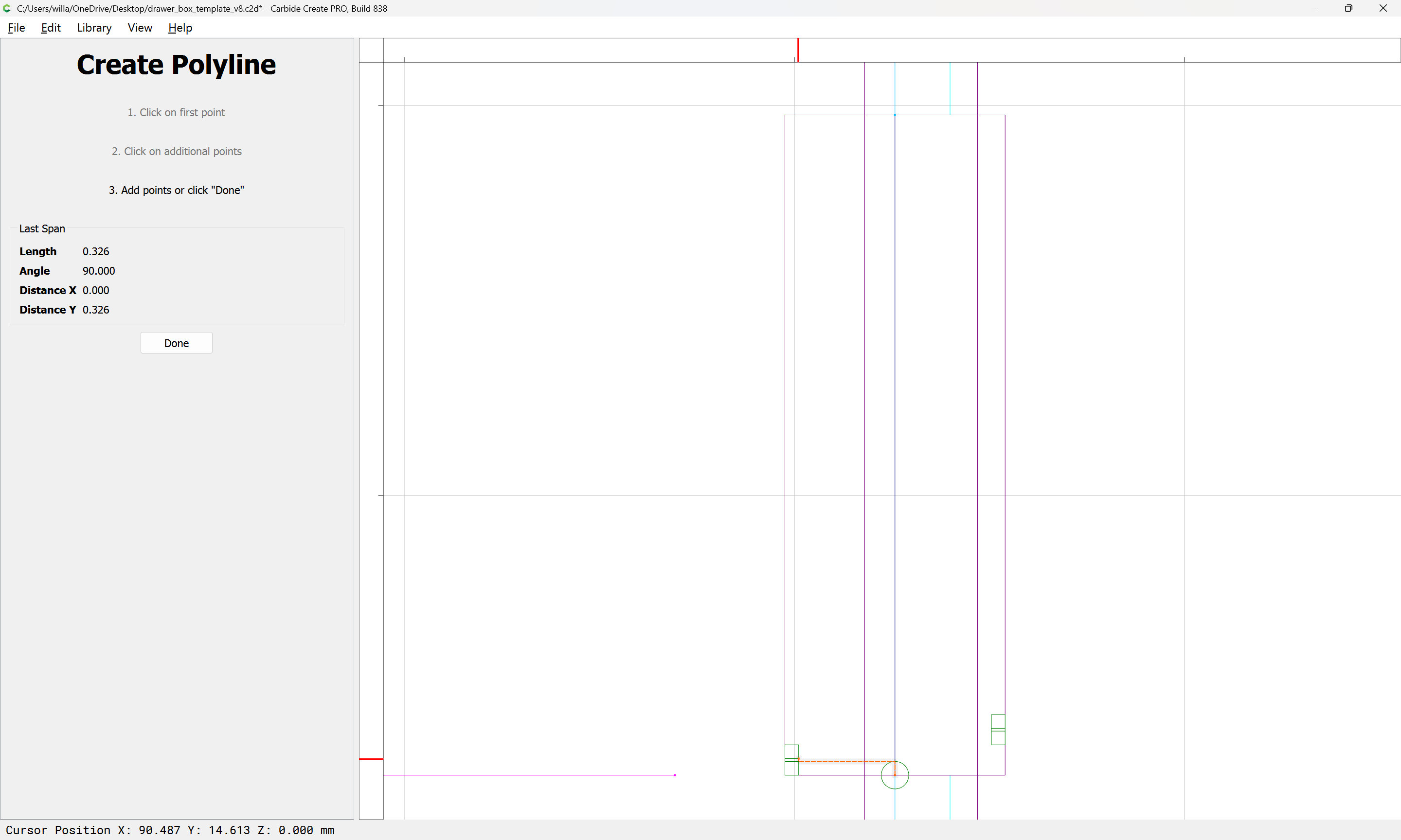
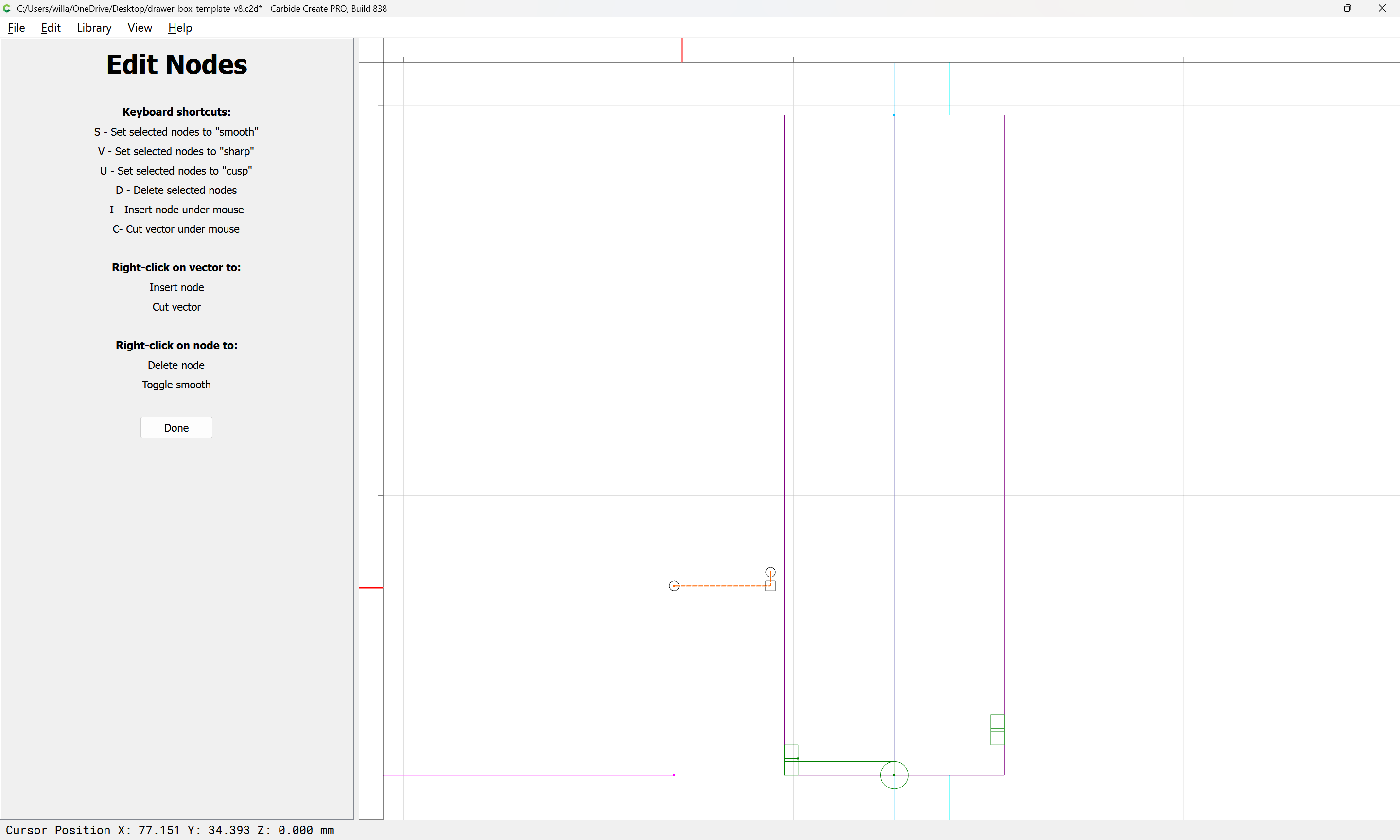
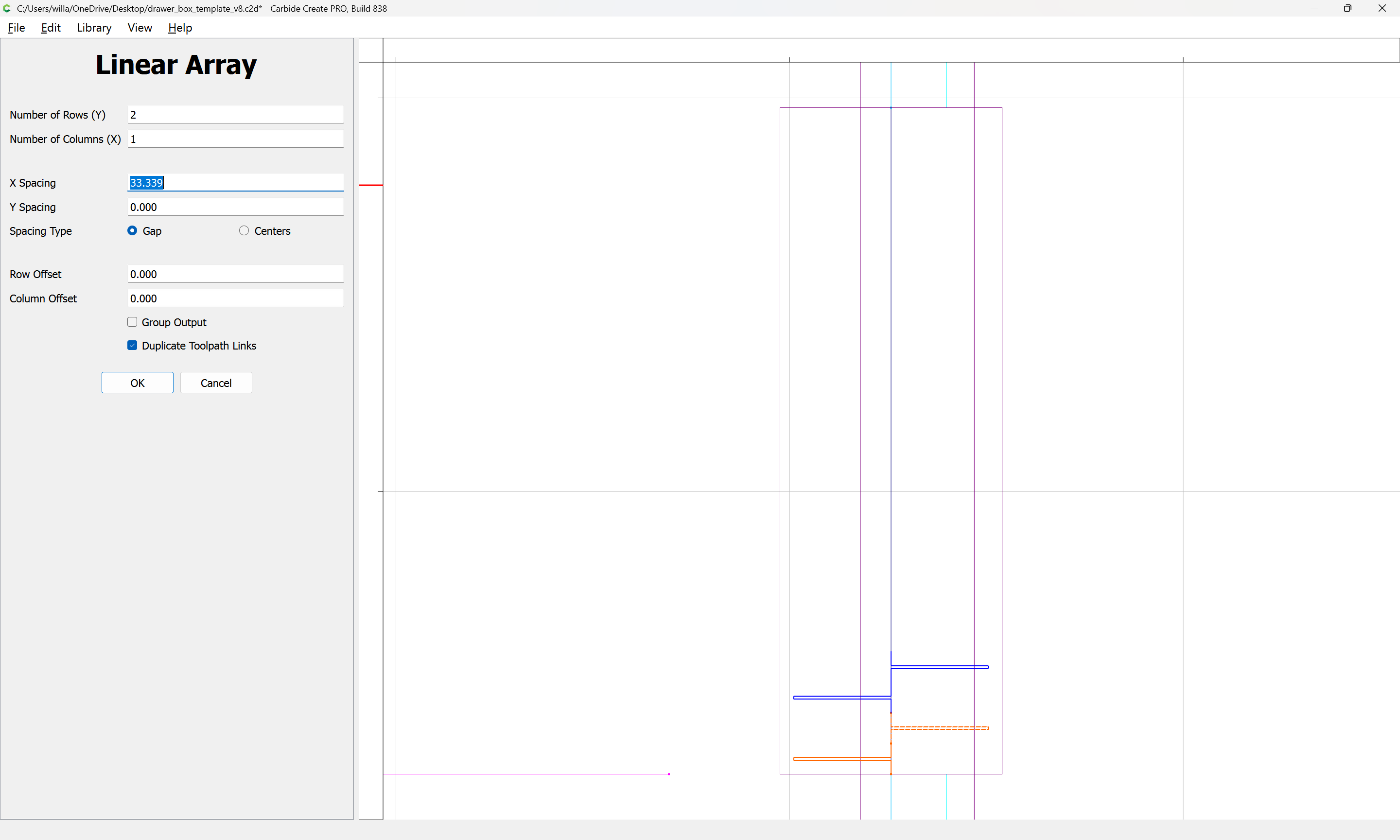
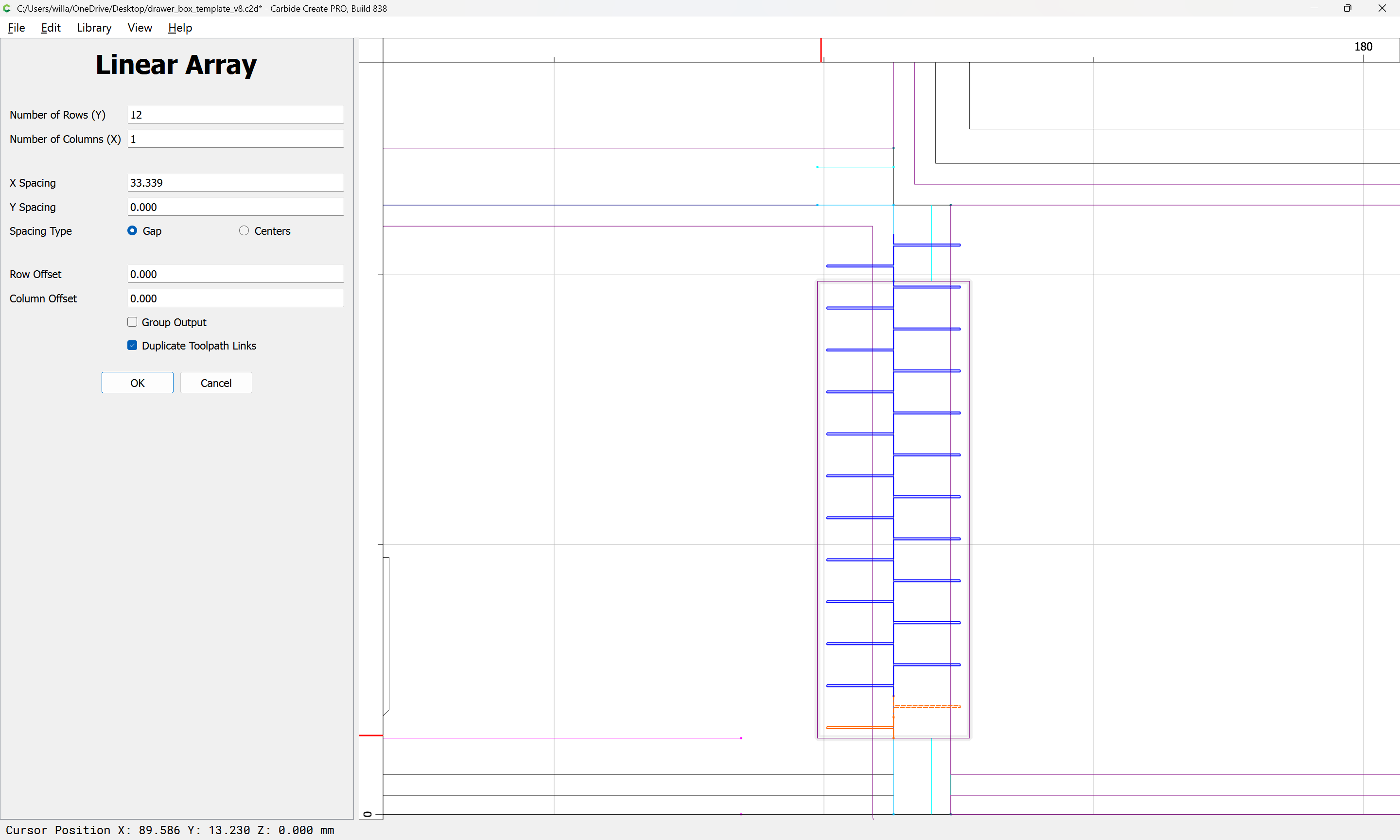
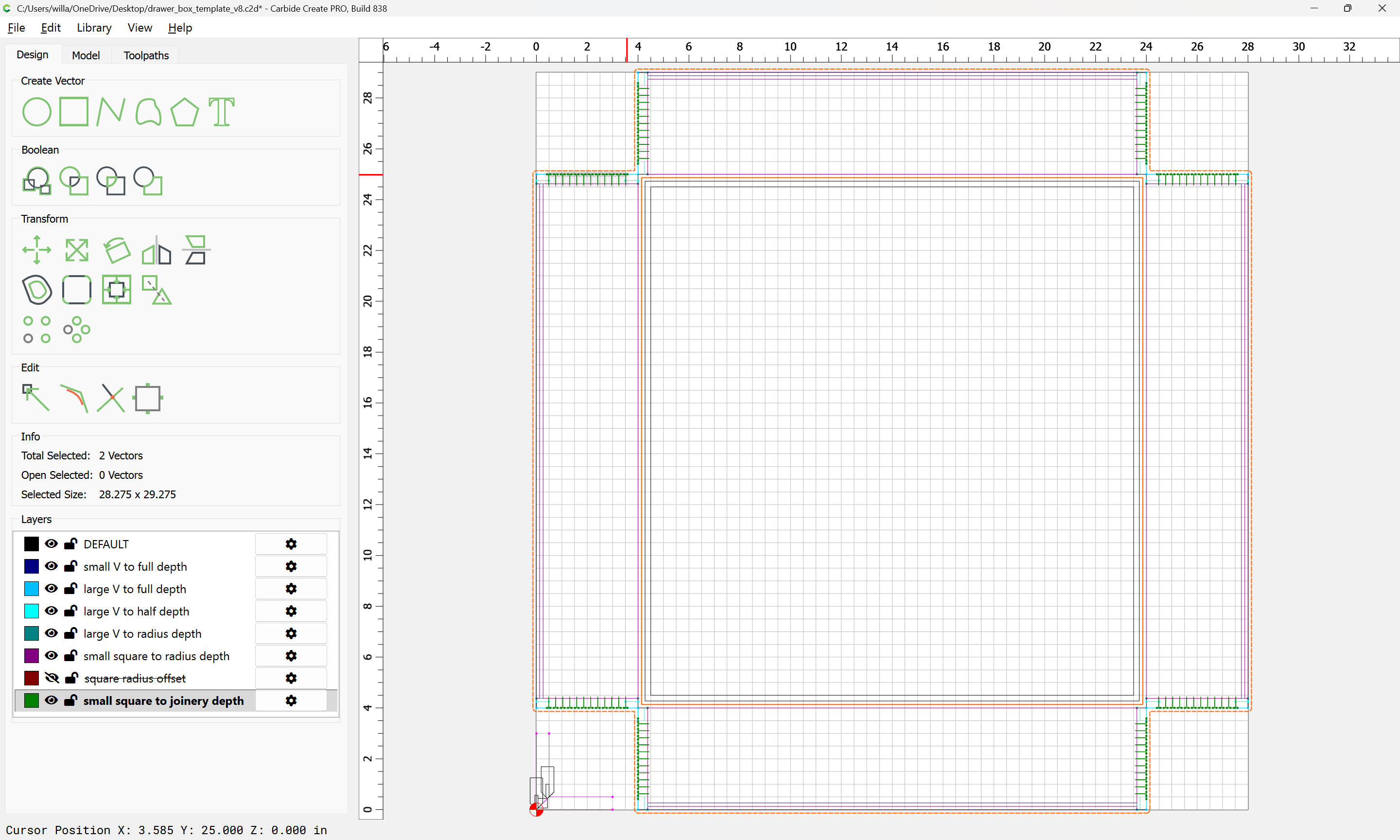
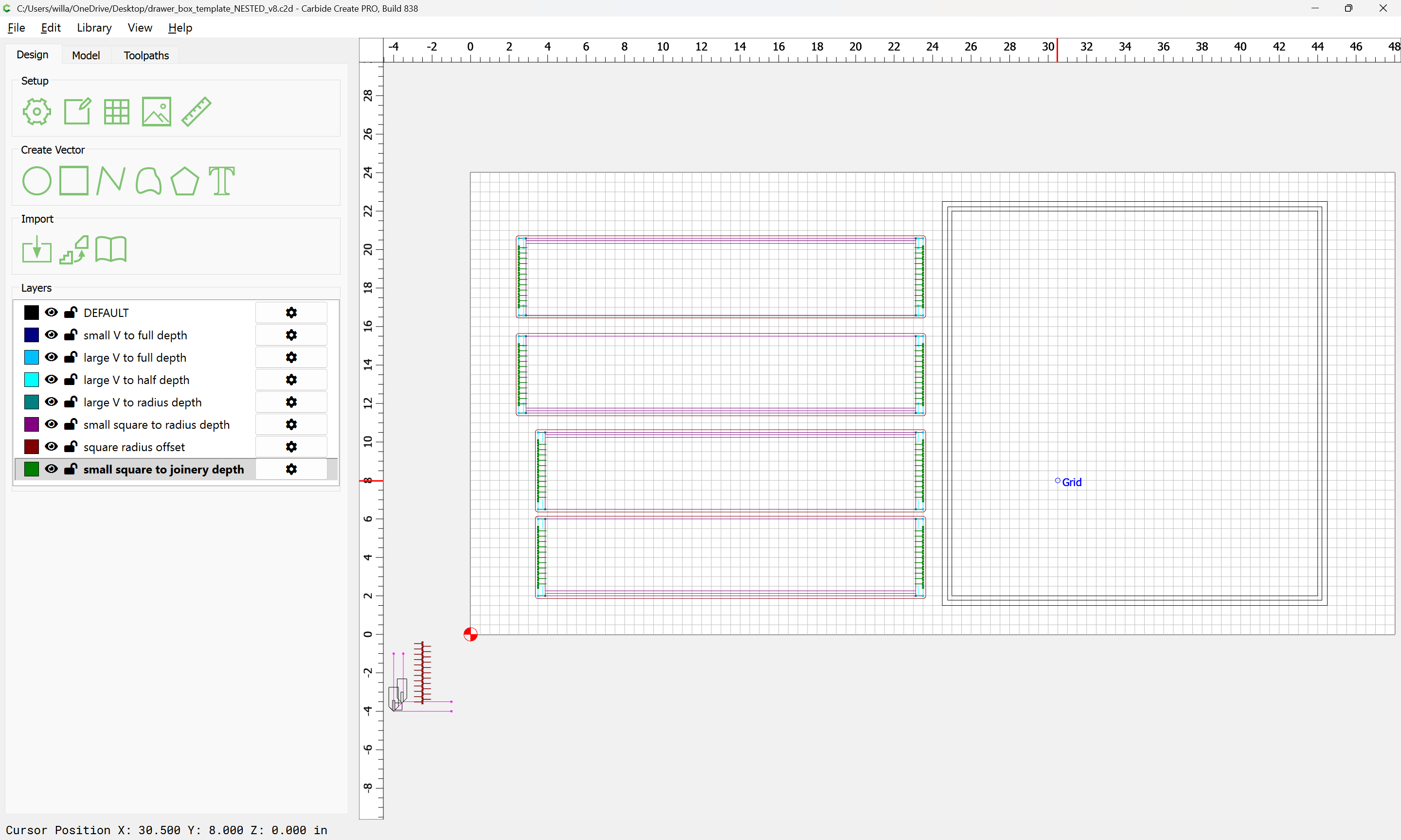
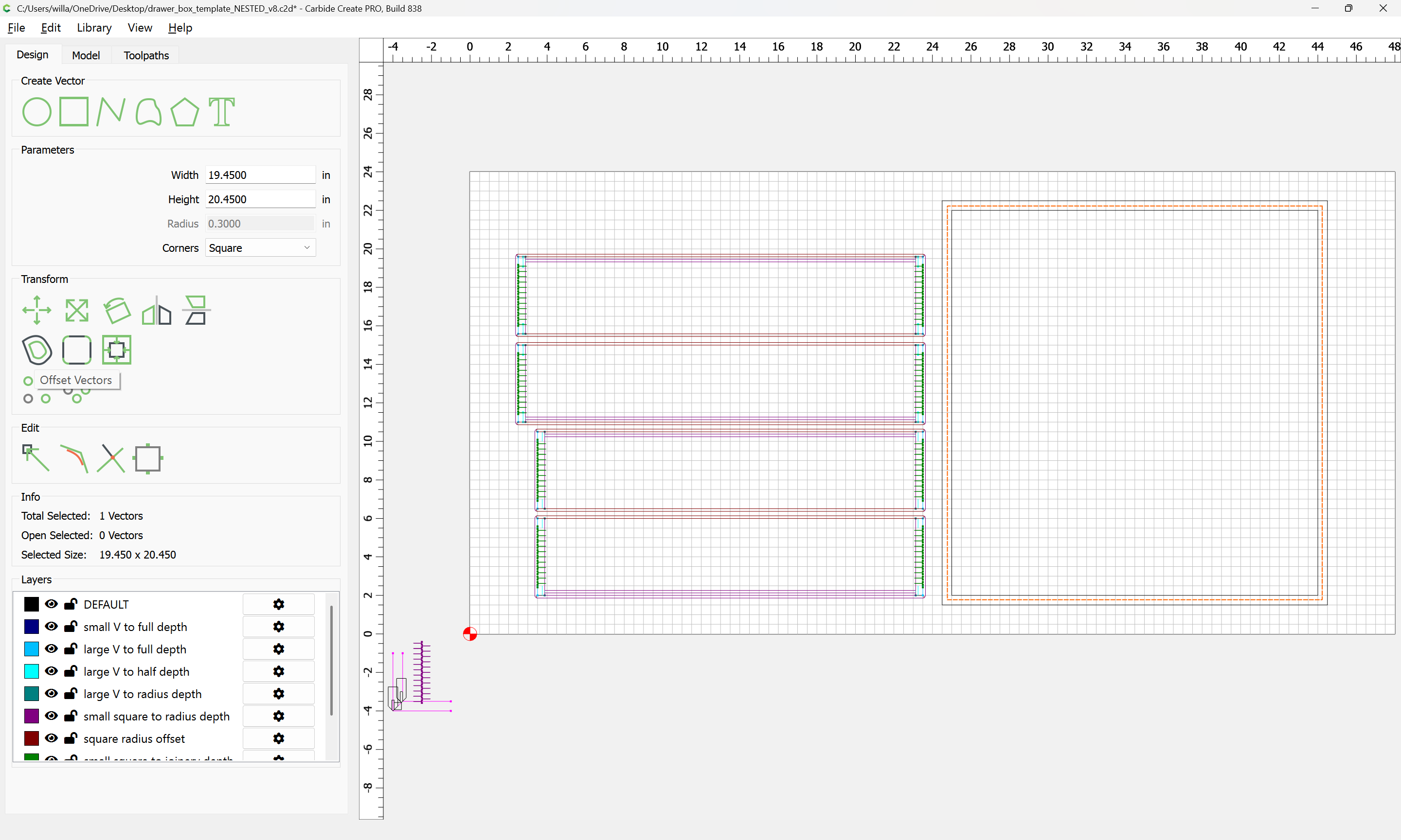
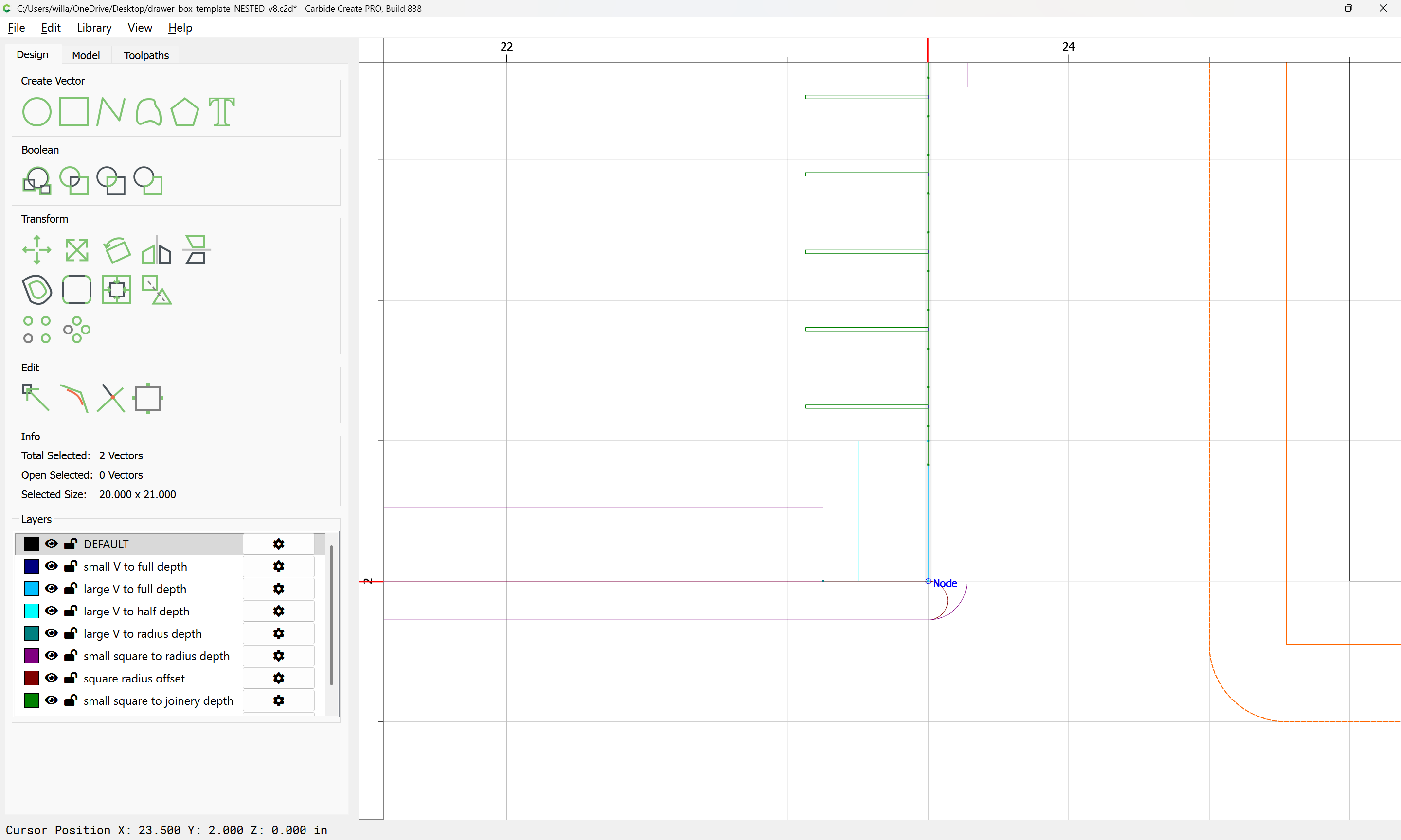
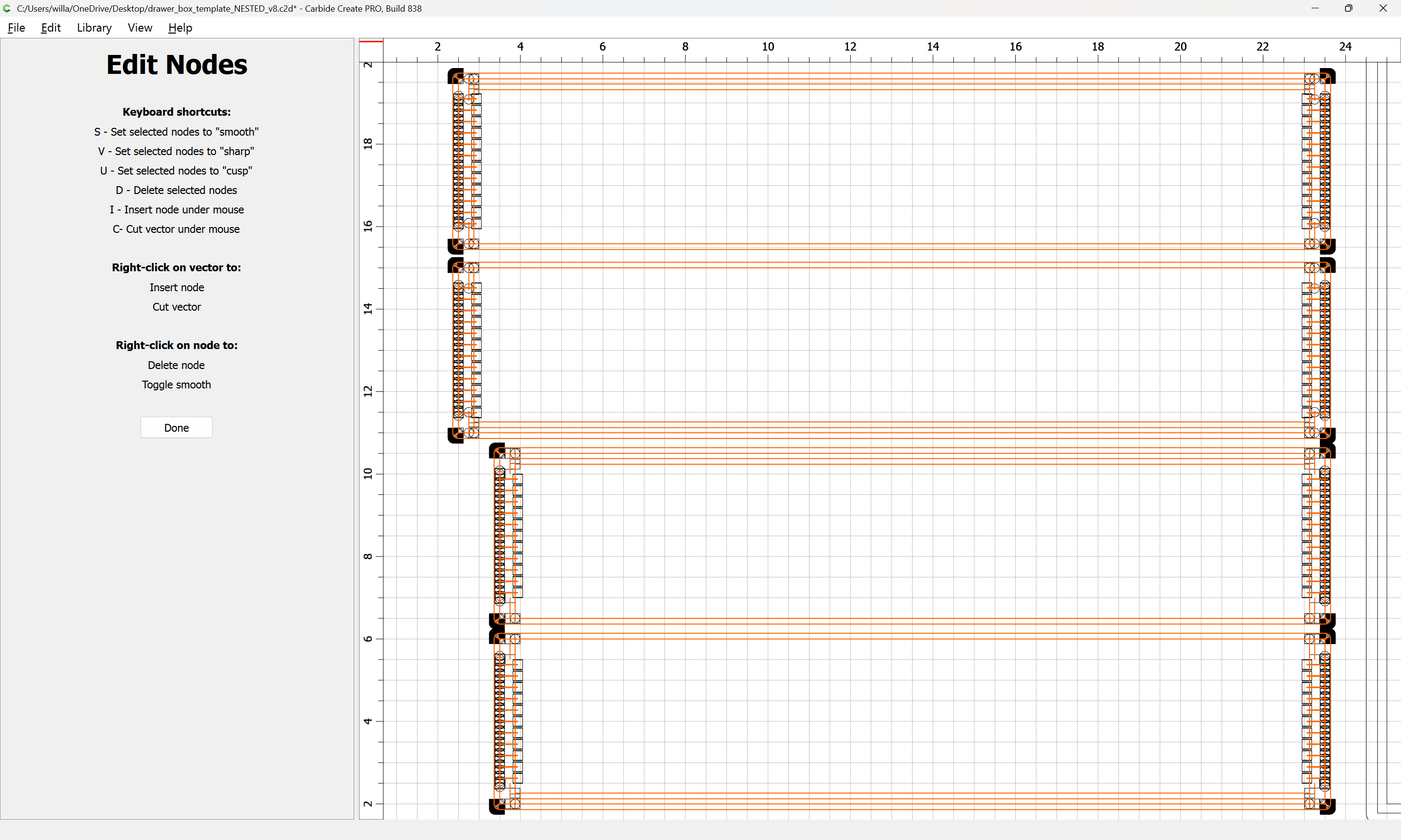
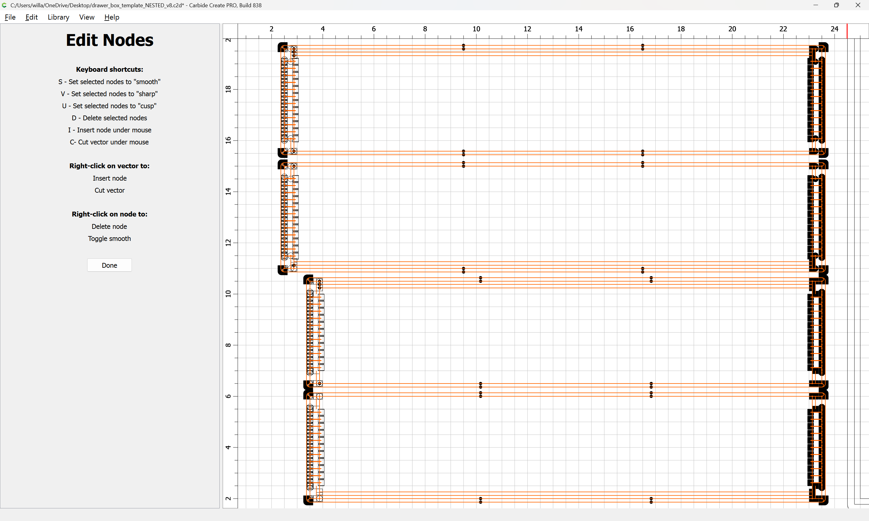
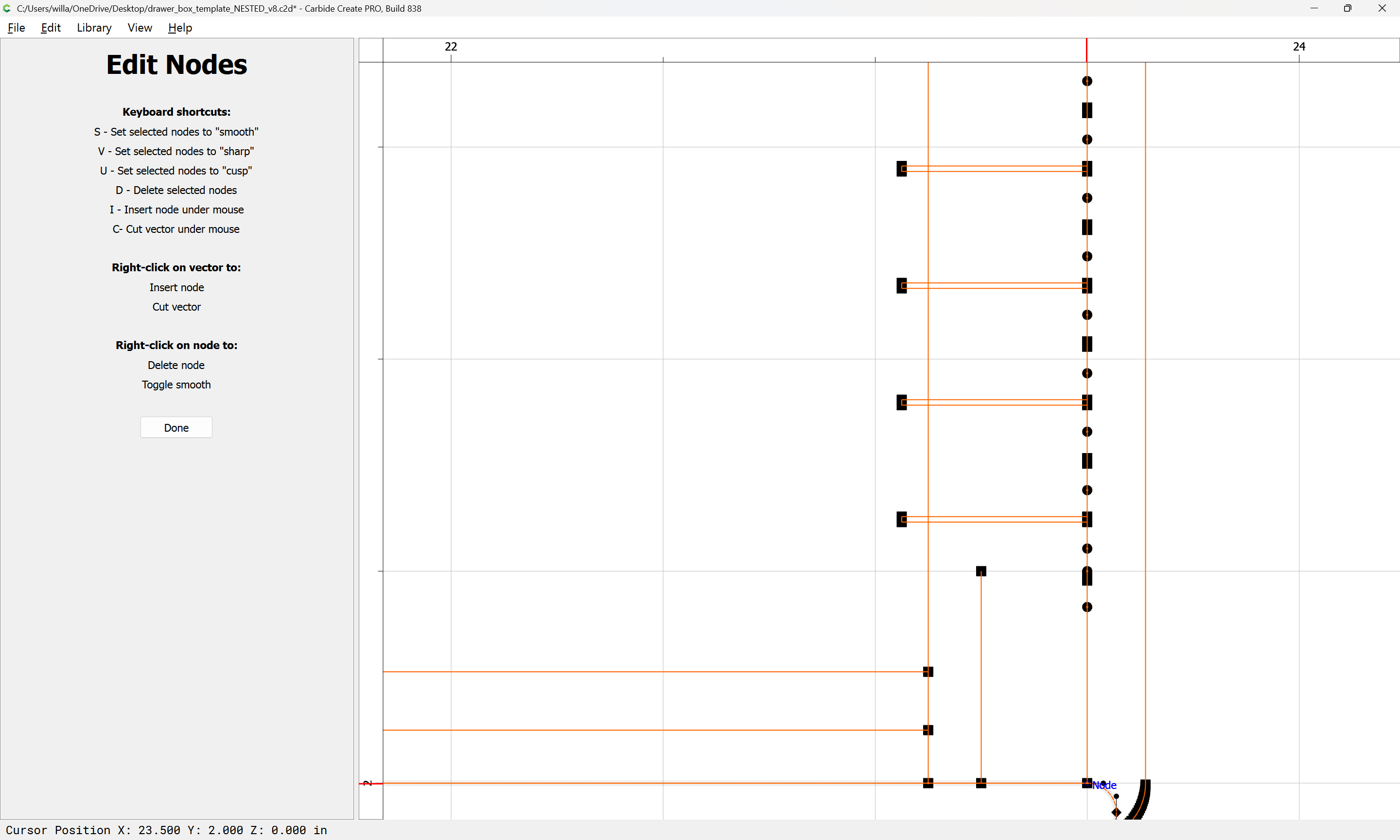
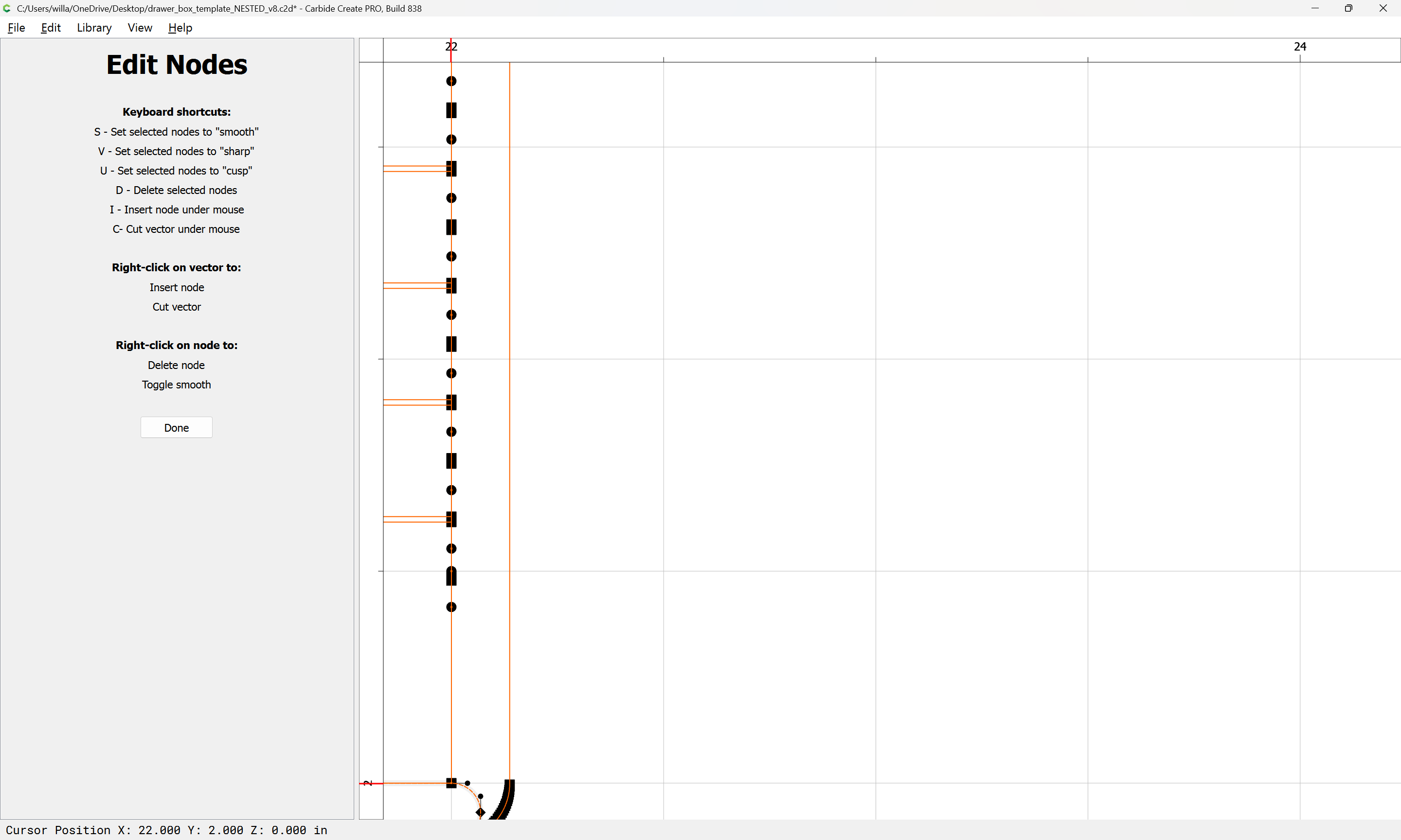
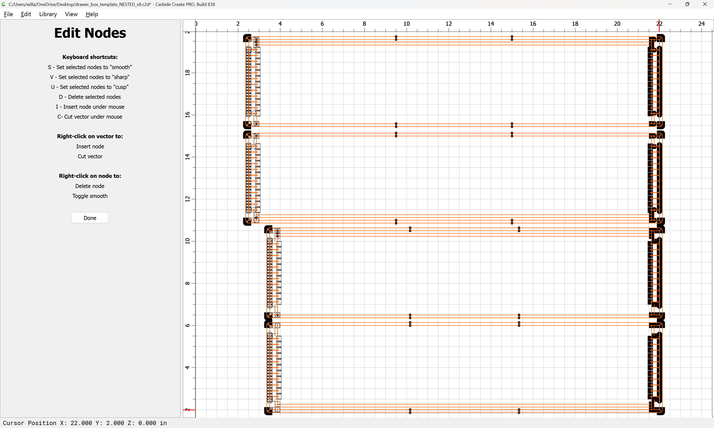
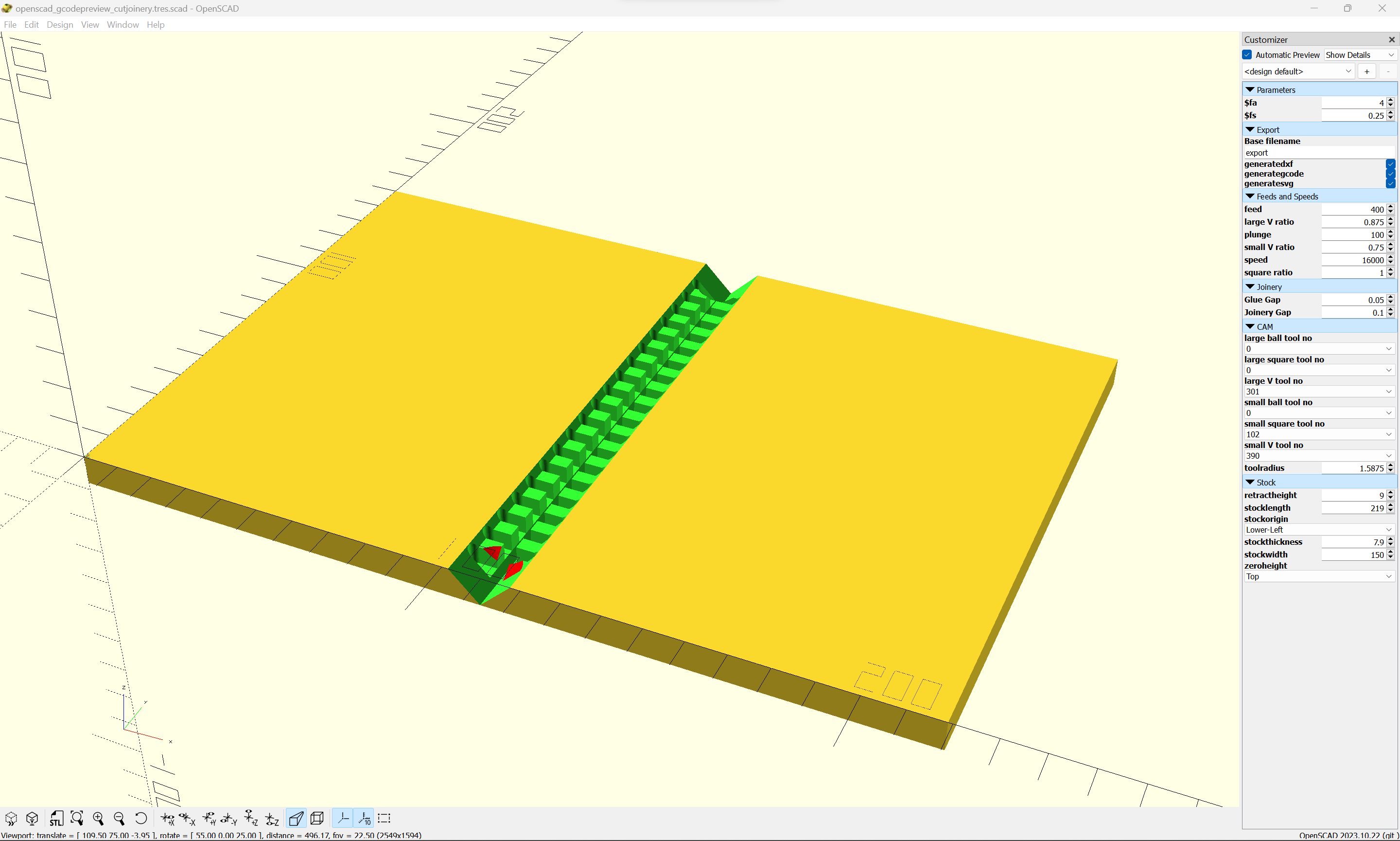
Now that Node Editing will snap to Grid intersections, it should be possible to set up a such a design for a given set of dimensions, then change to a different dimension for depth and width (but not height) so long as things snap to the grid. Hang on for a walk-through of this…
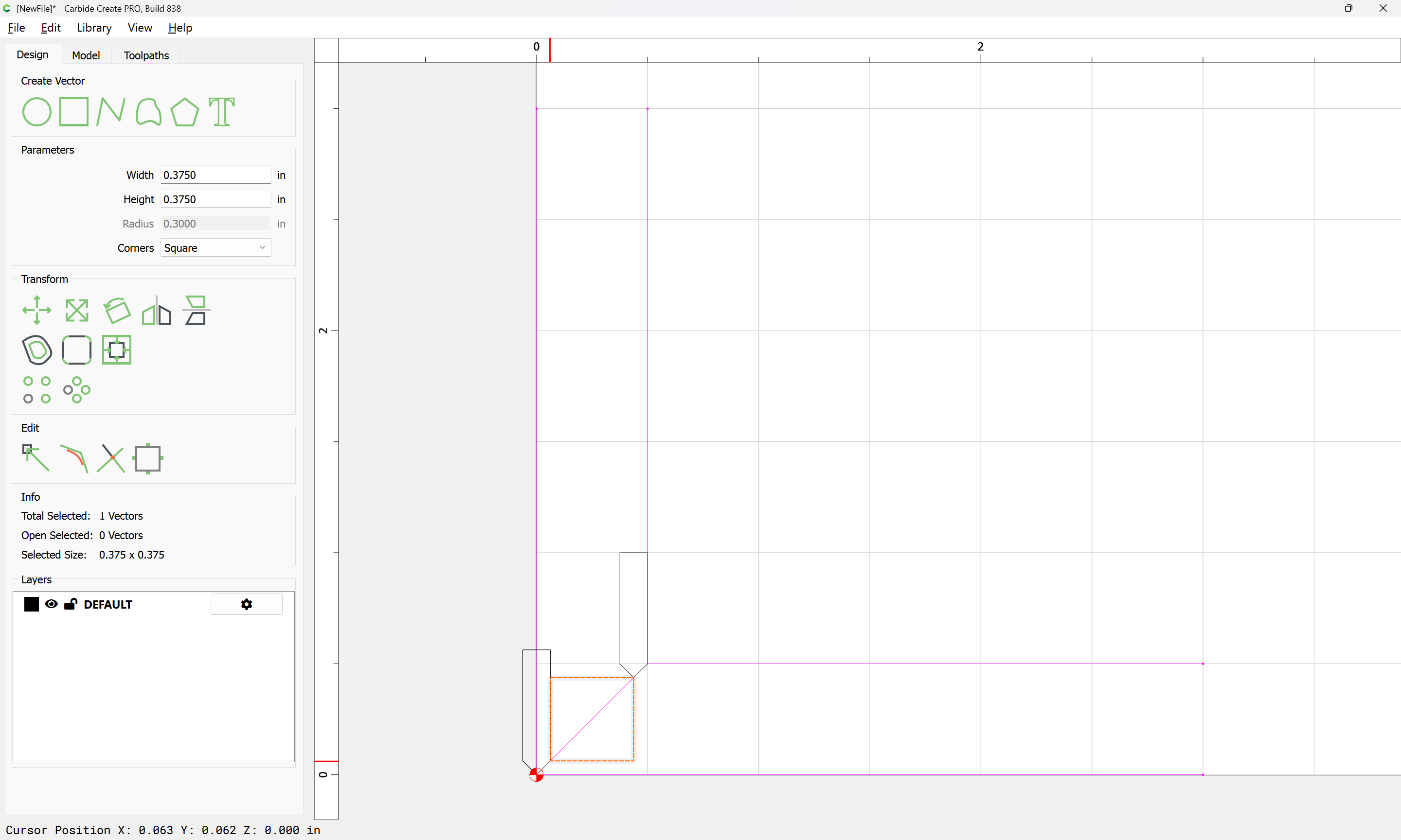
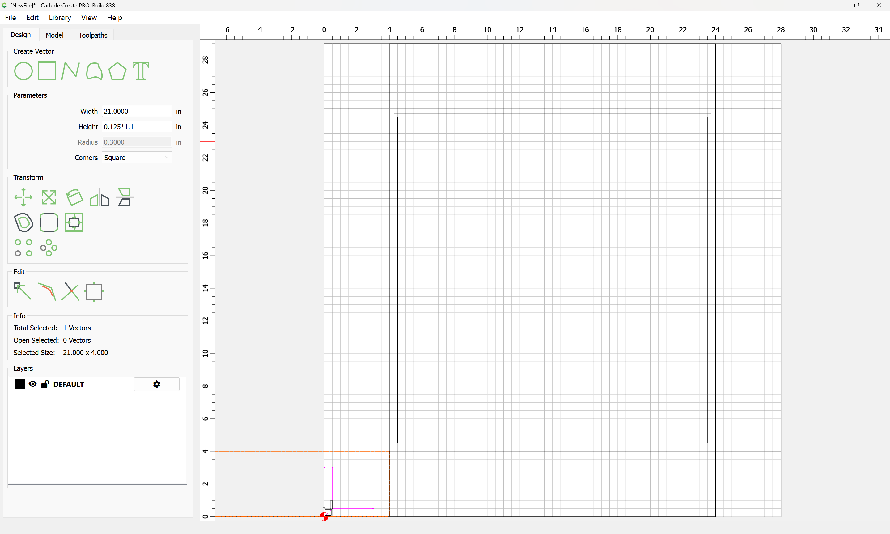
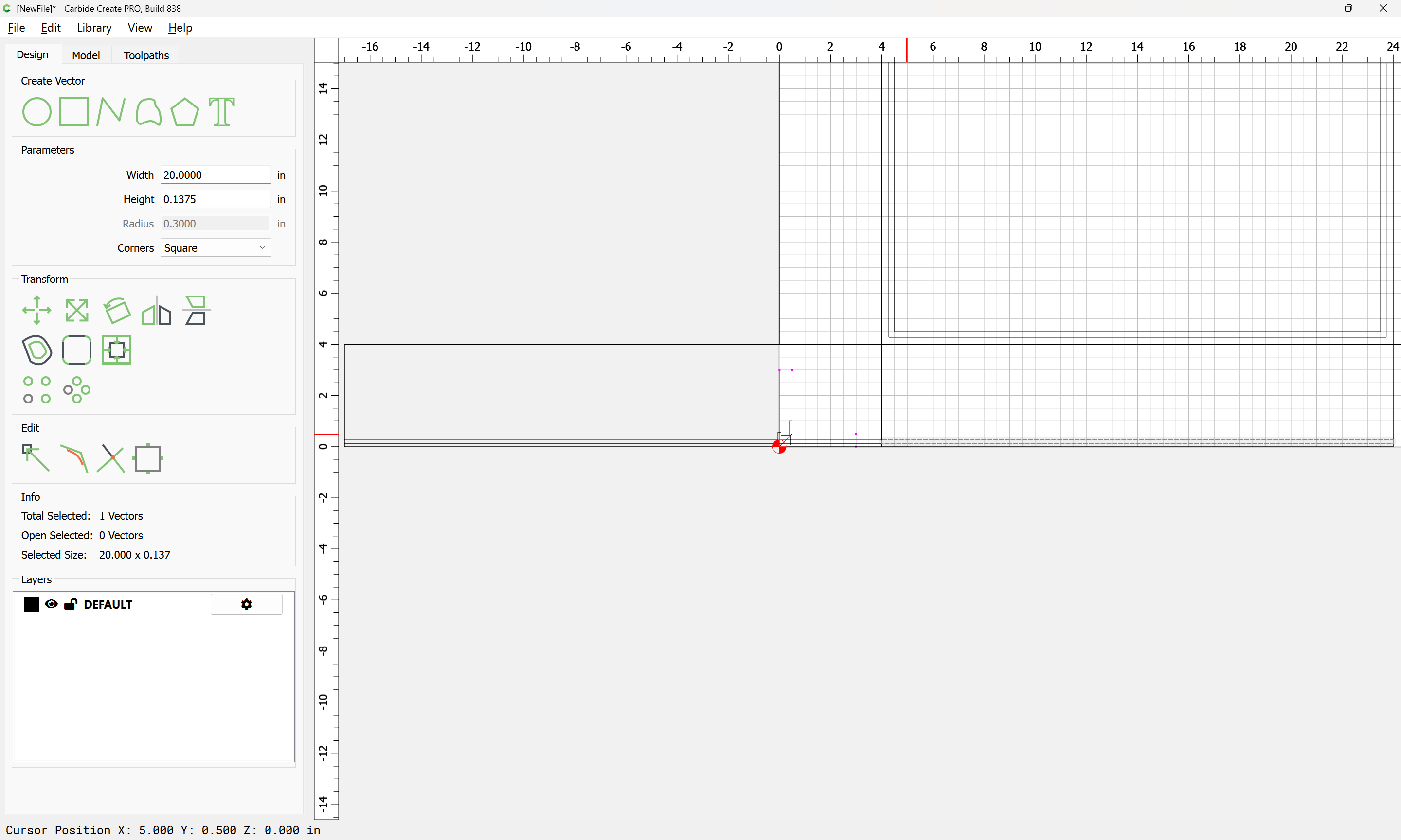
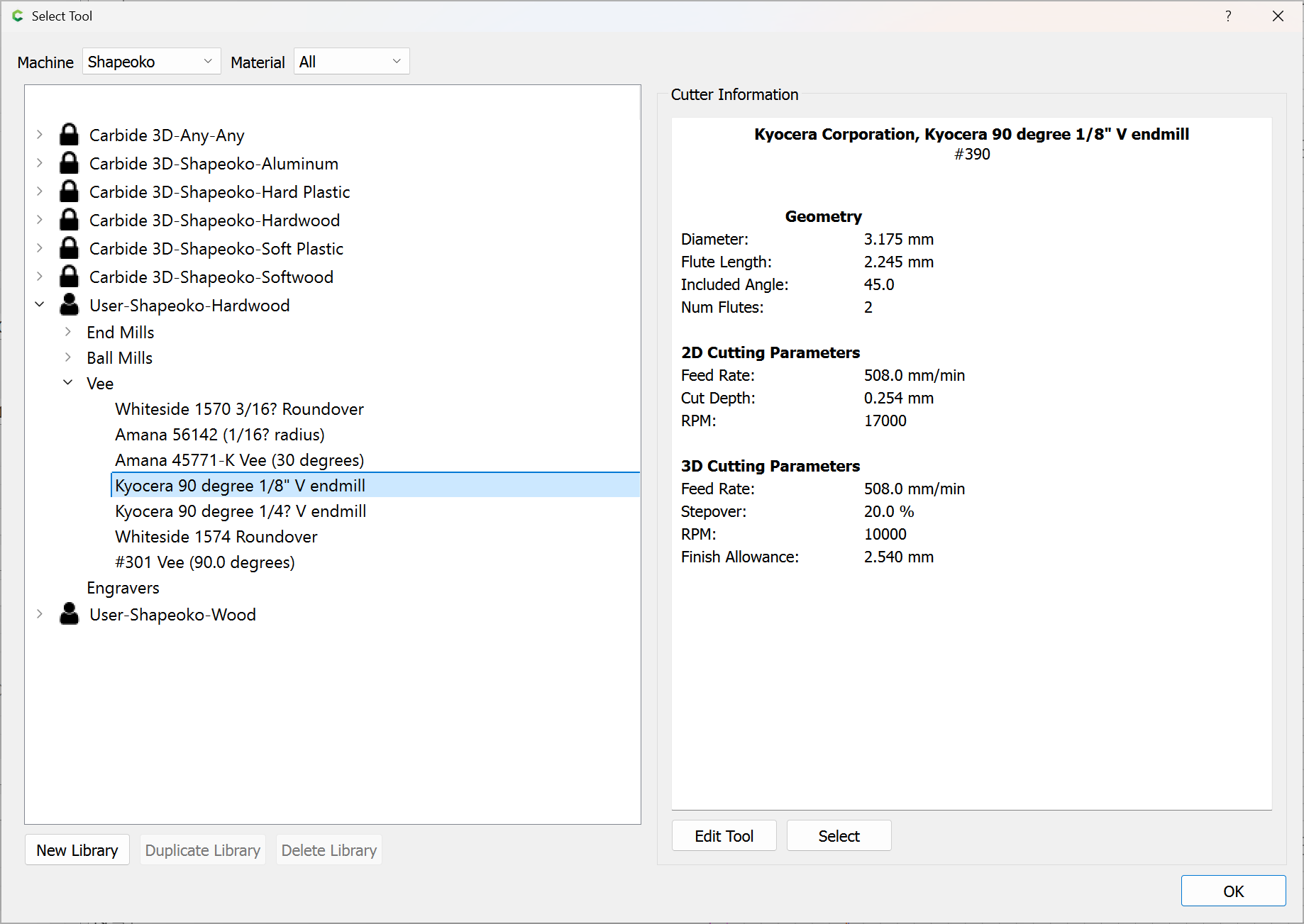
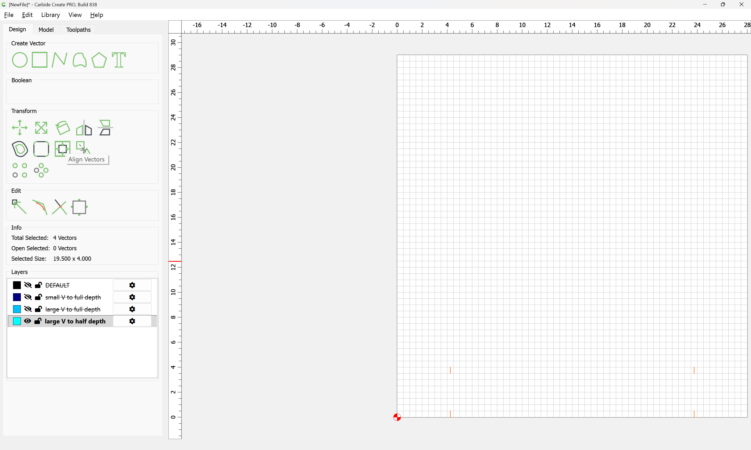
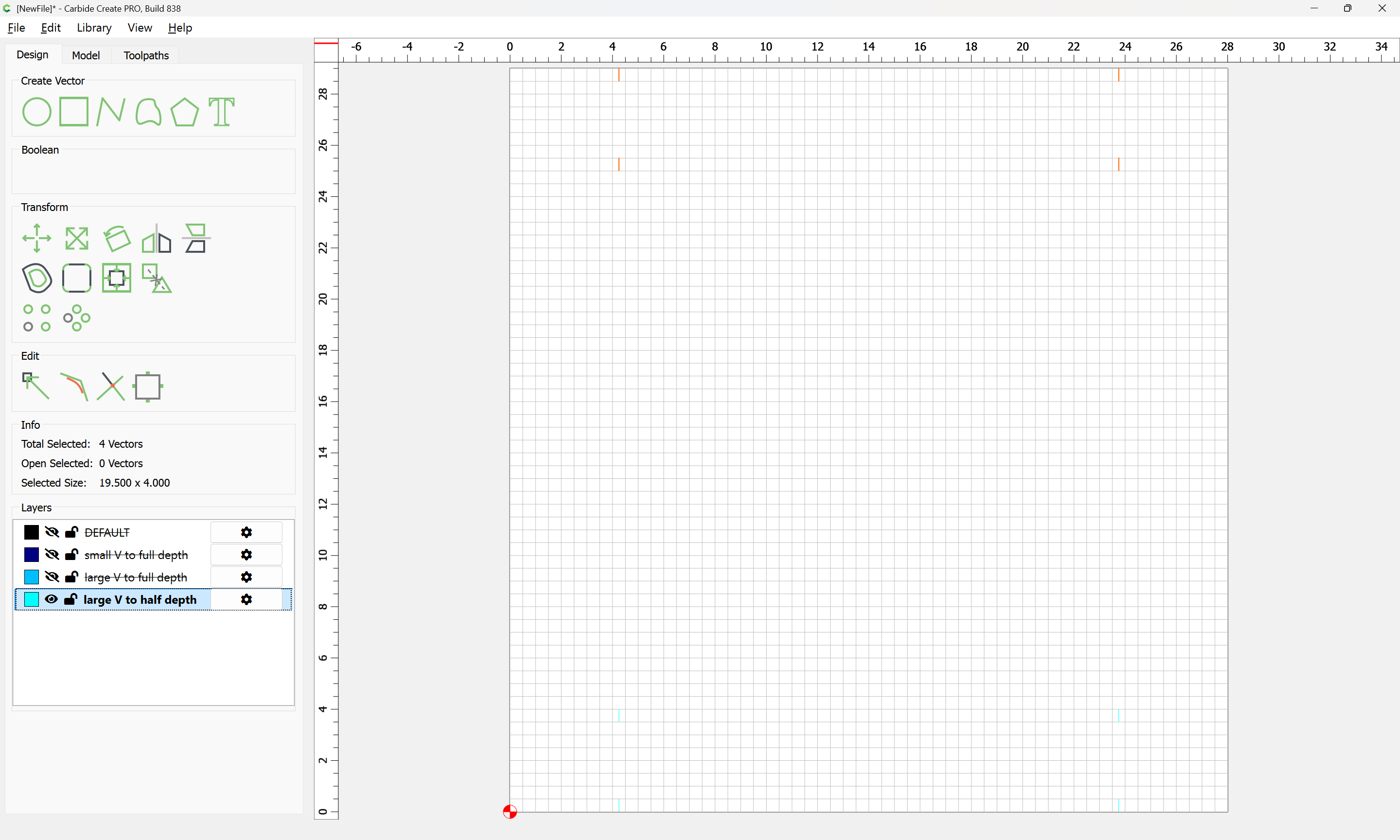
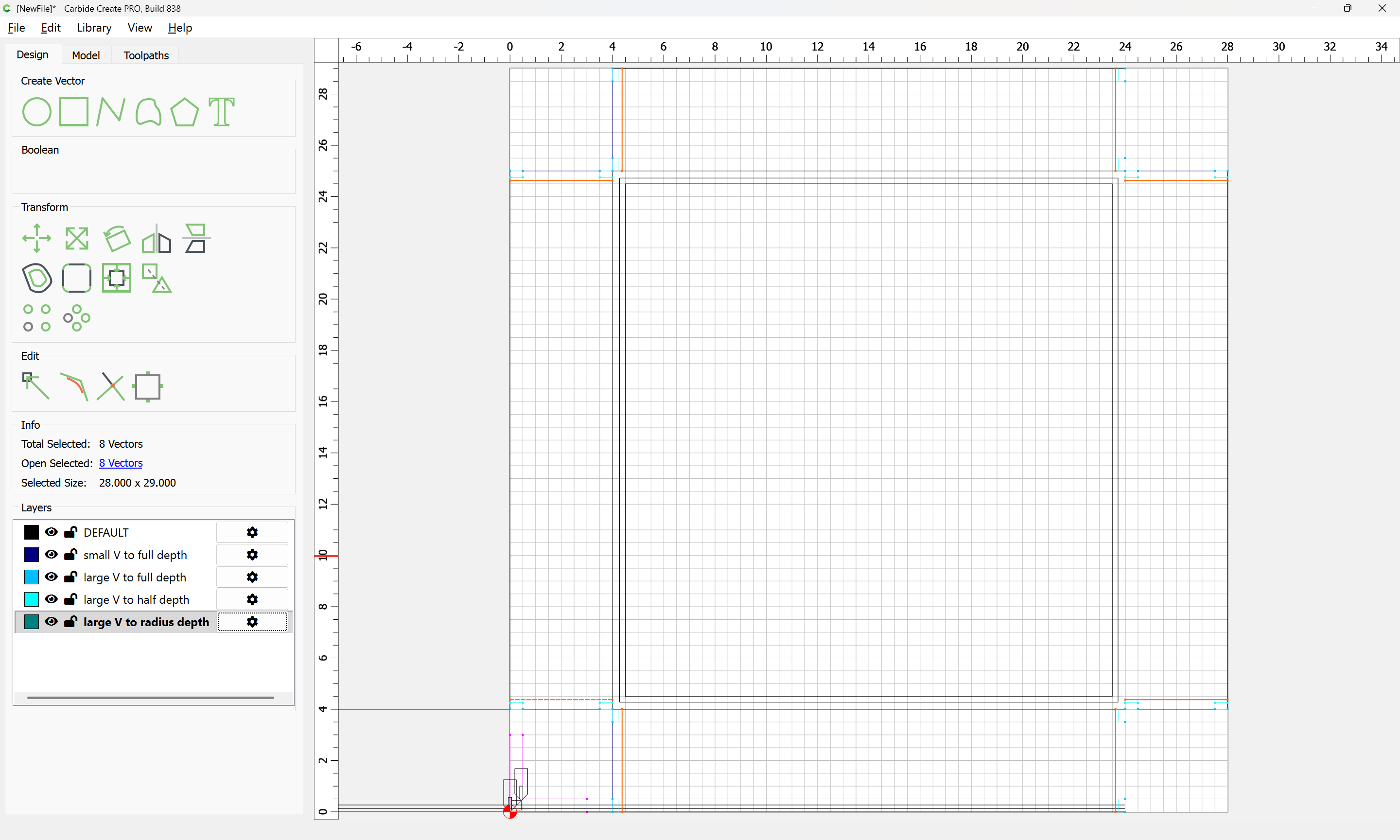
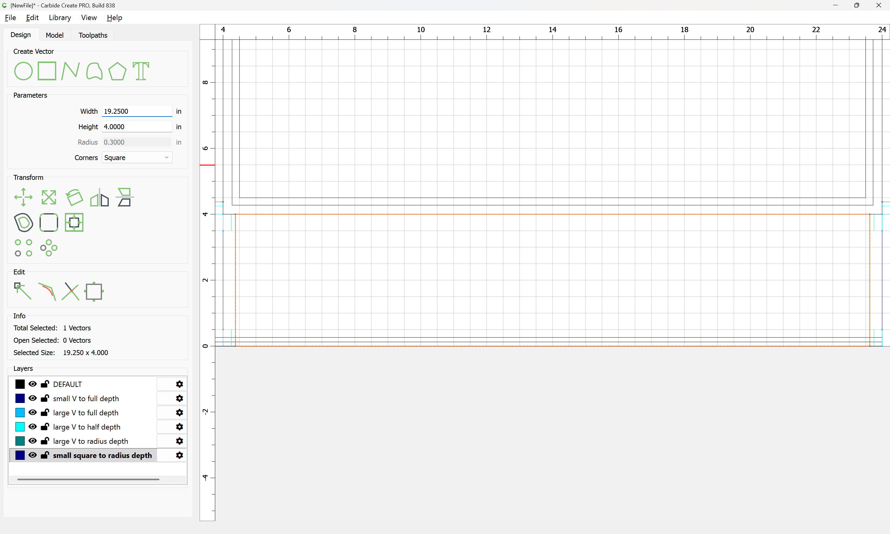
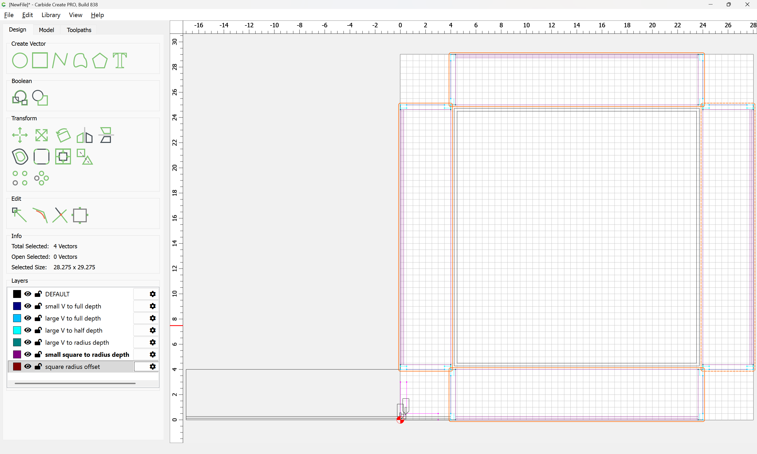
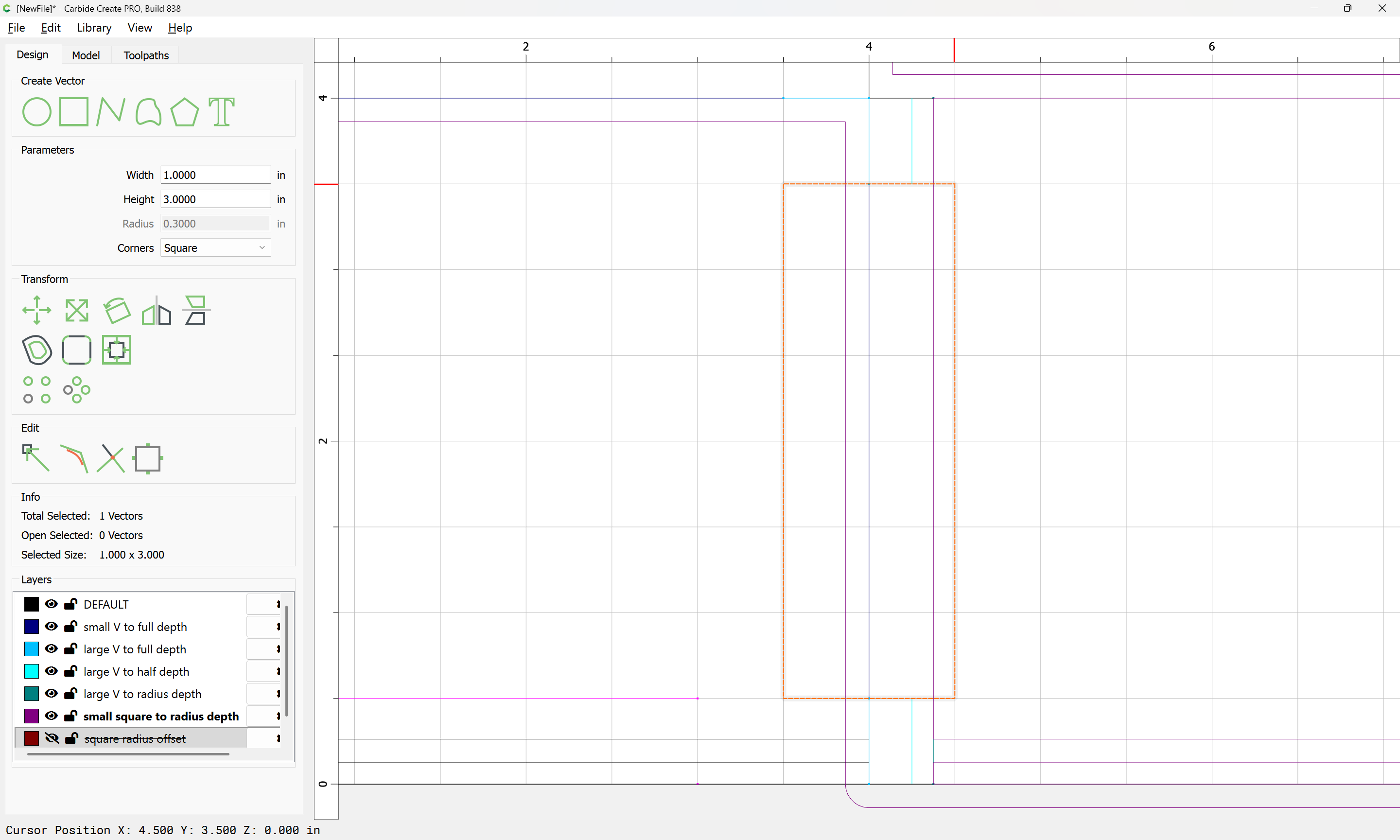
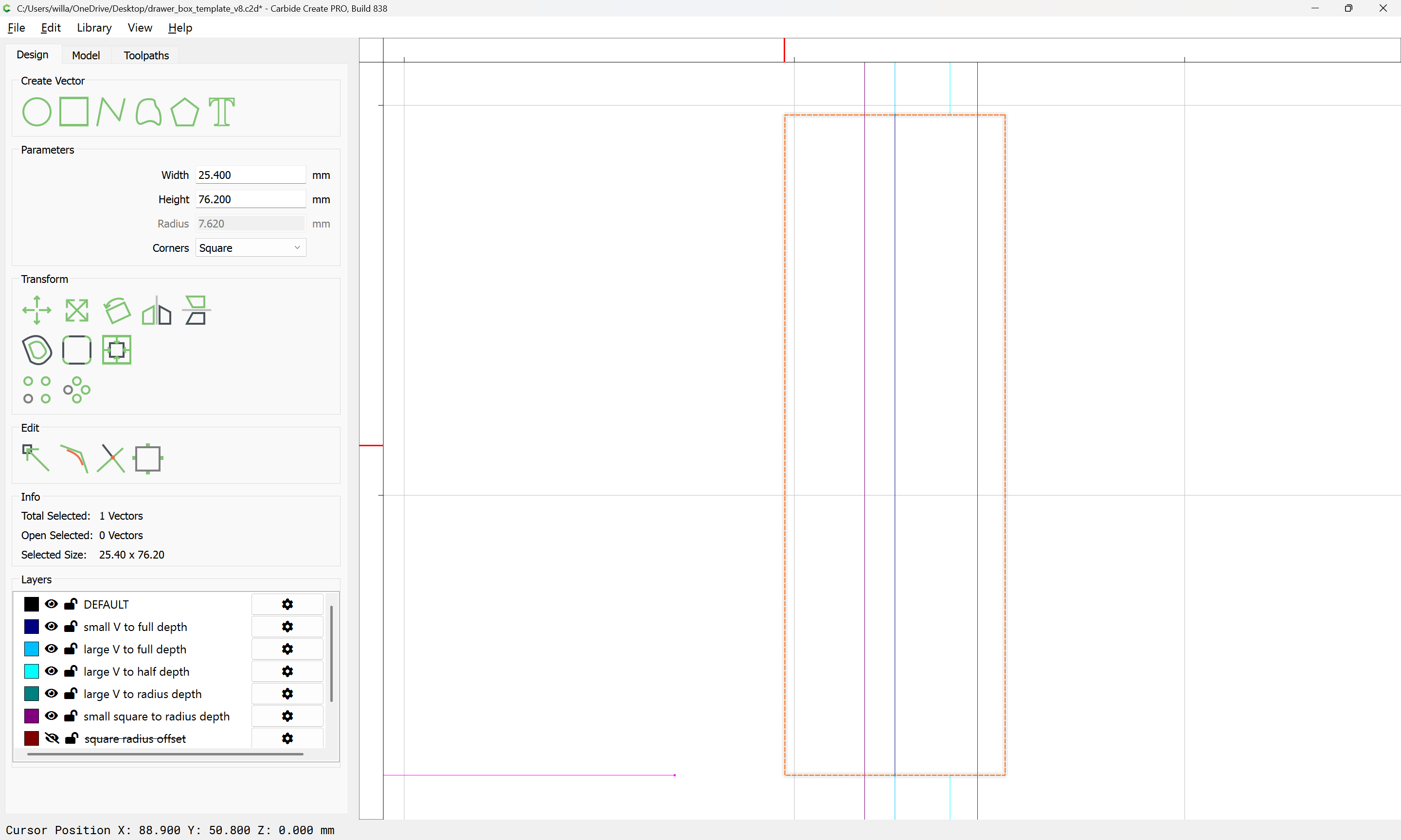
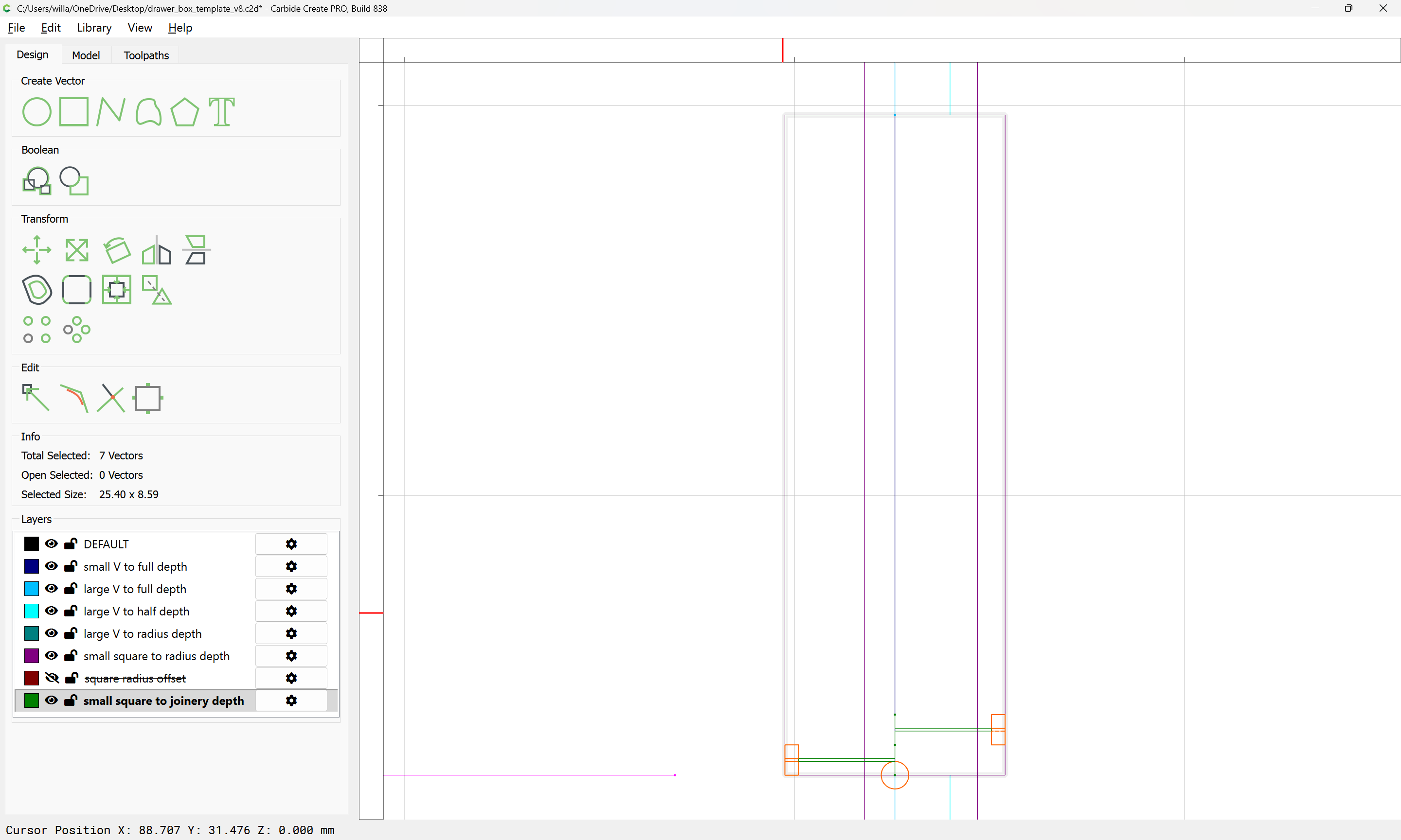
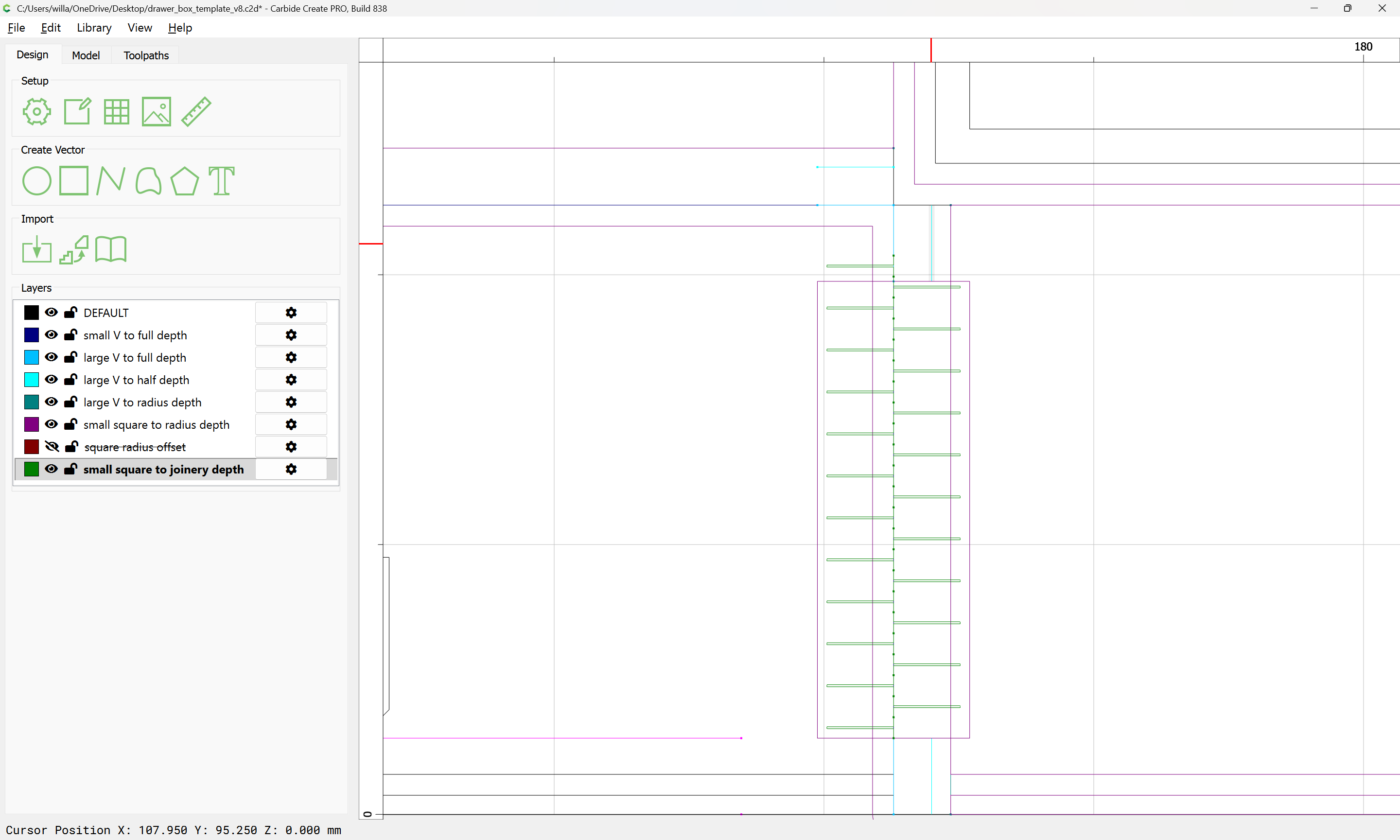
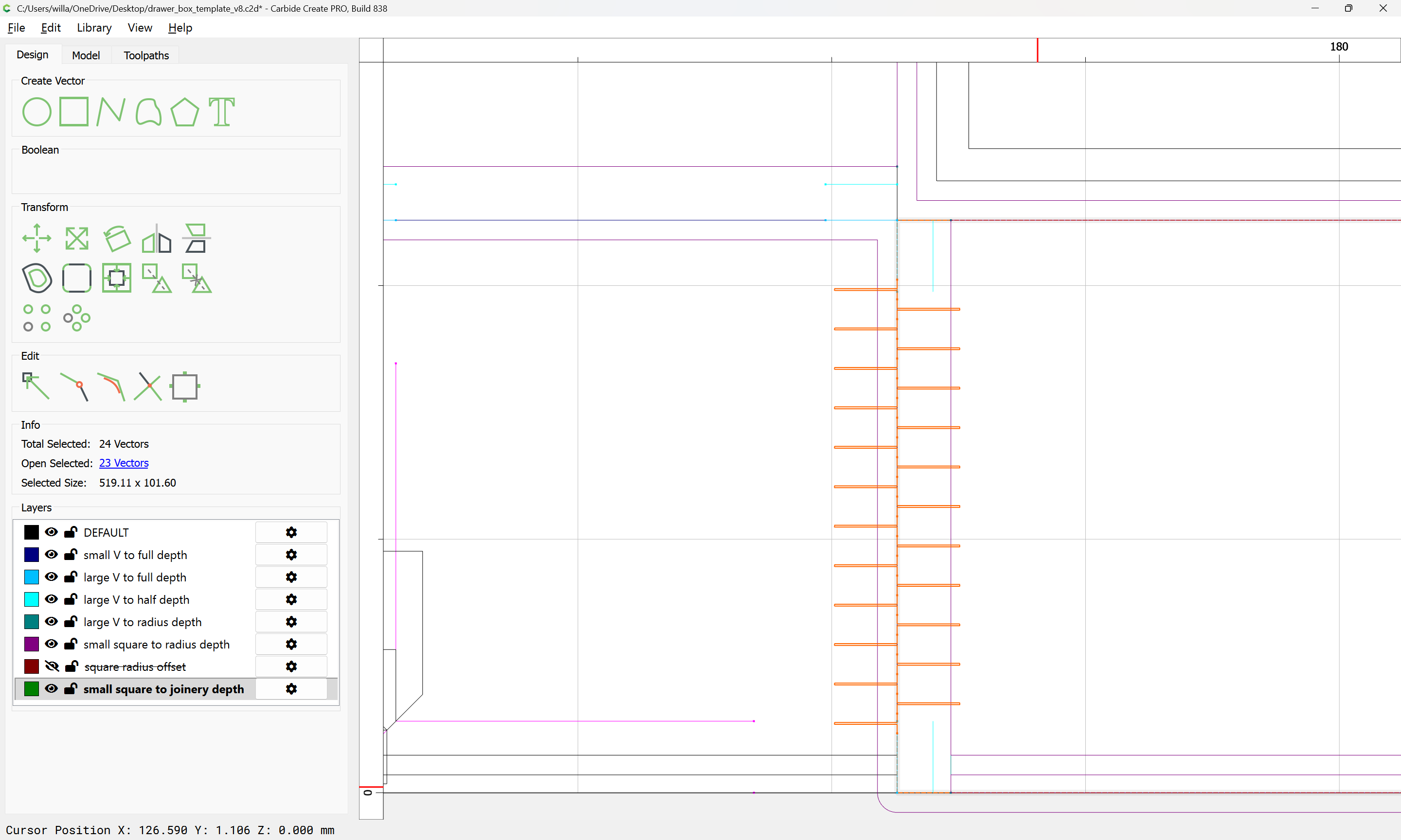
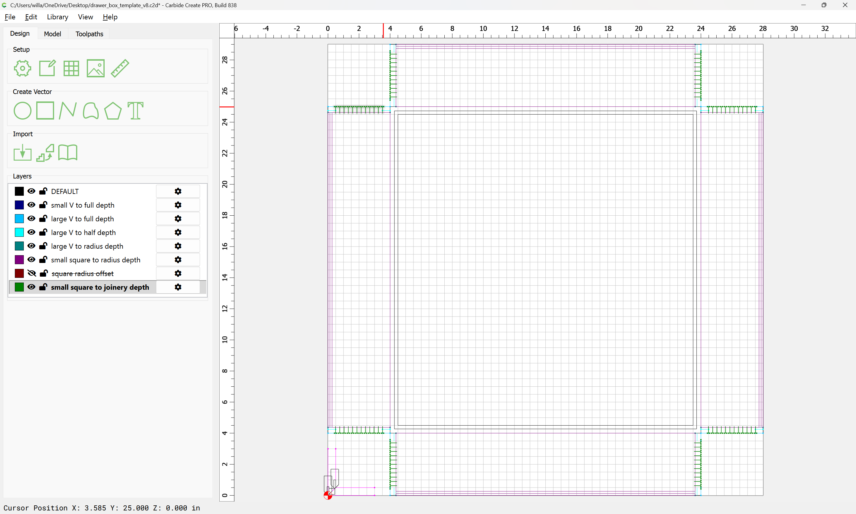
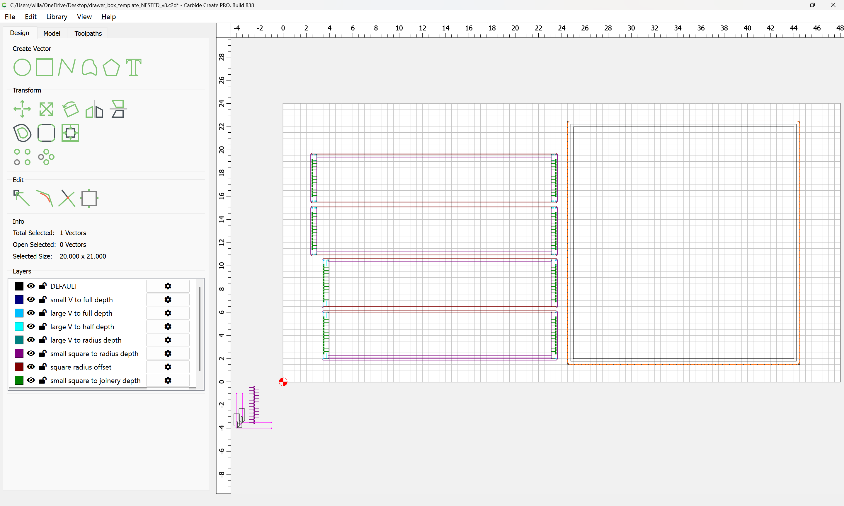
For reference, we draw the tooling which will be used:
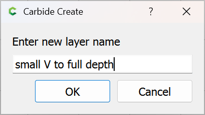
small V (1/8" 90 degree V endmill)
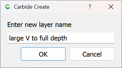
large V (1/2" 90 degree V endmill)
small square (1/8" square tool)
large square (1/4" square tool) — note that since the stock is so thin, it should be workable to eschew the larger square tool, trading removing less material for slower material removal rate
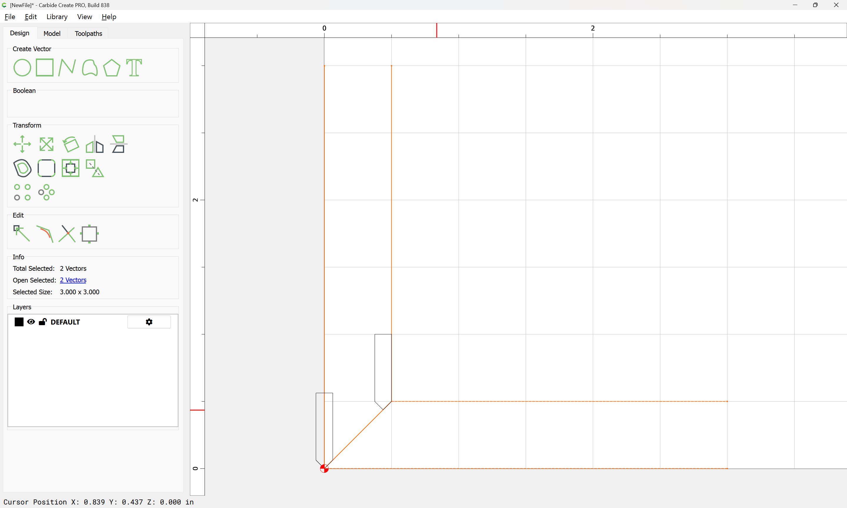
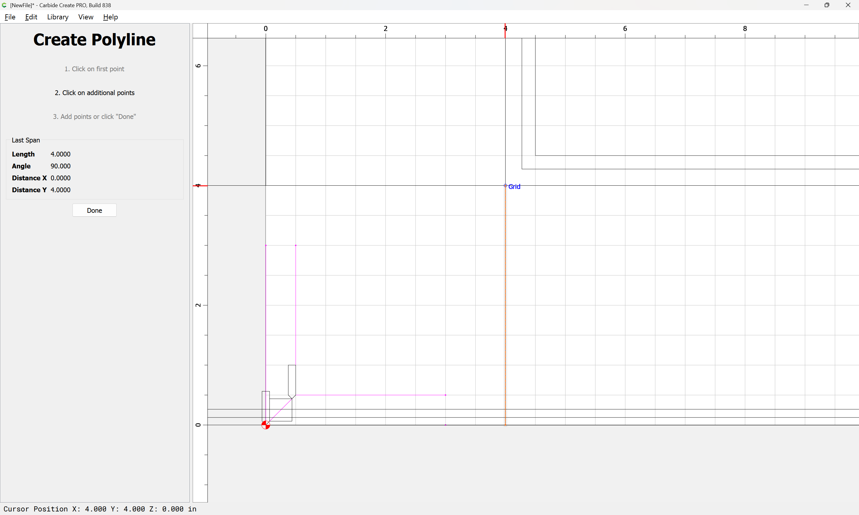
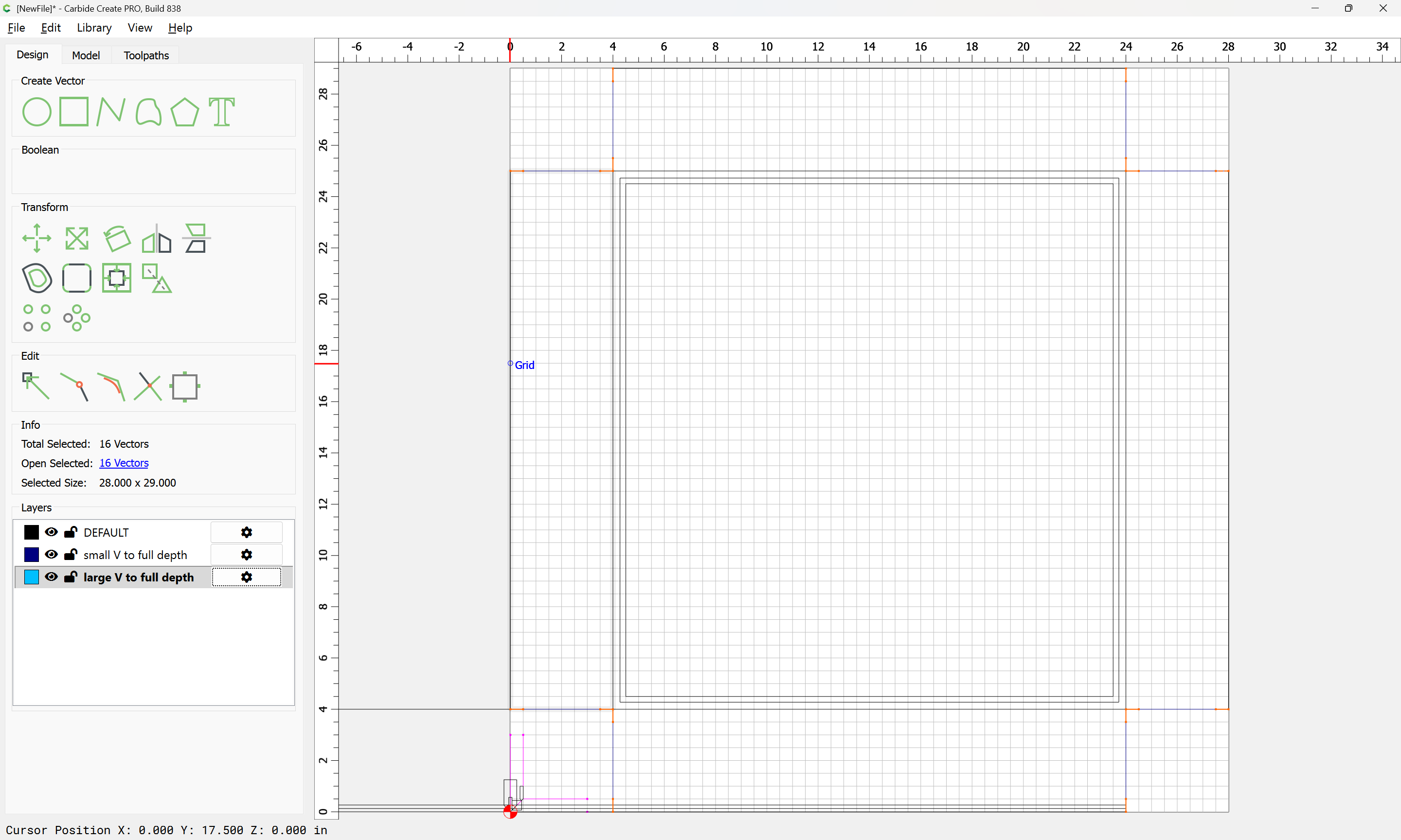
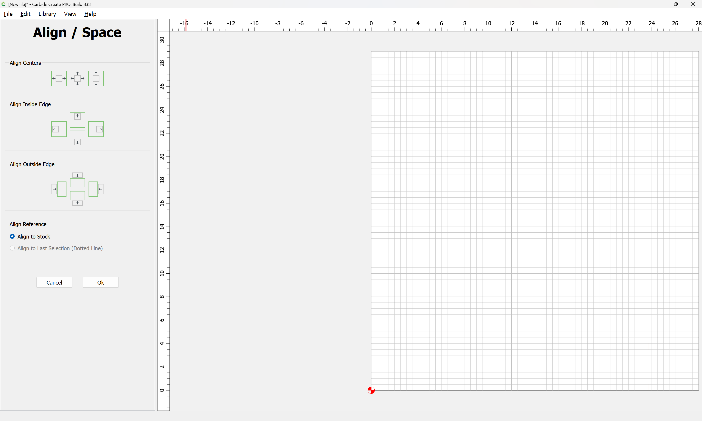
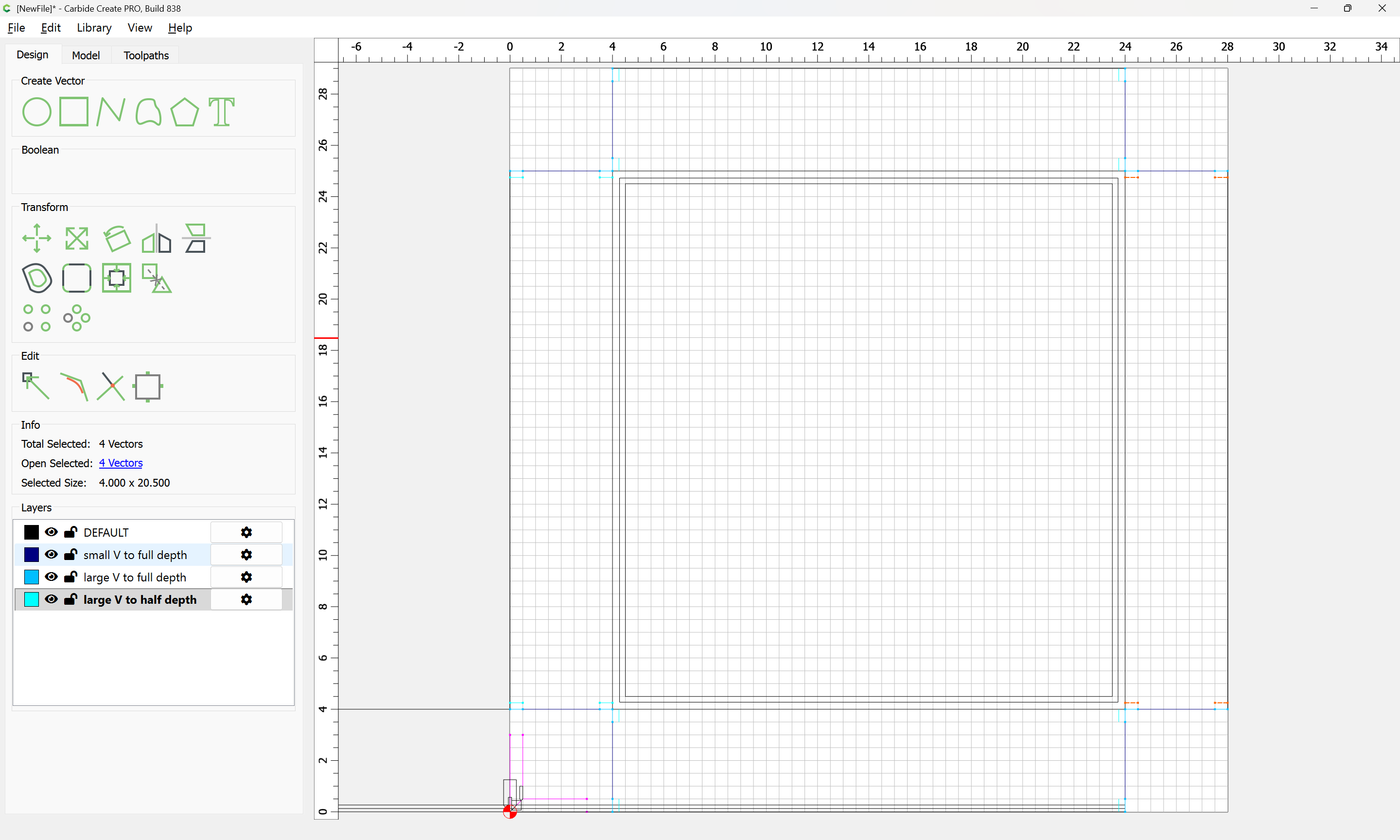
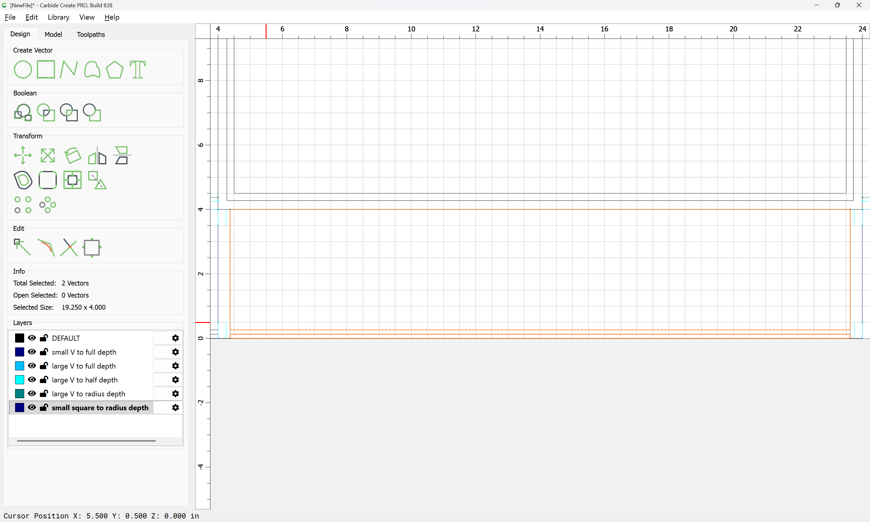
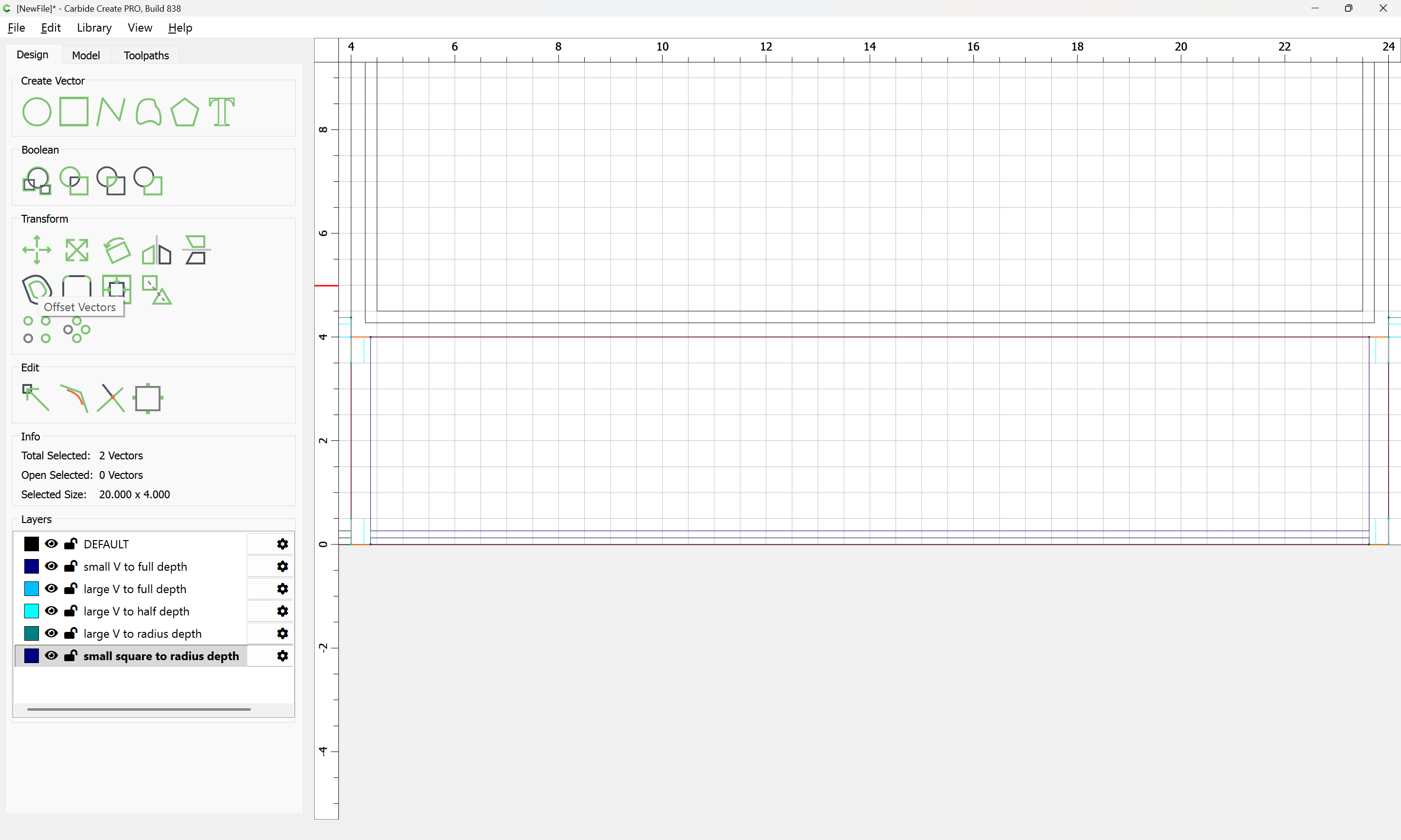
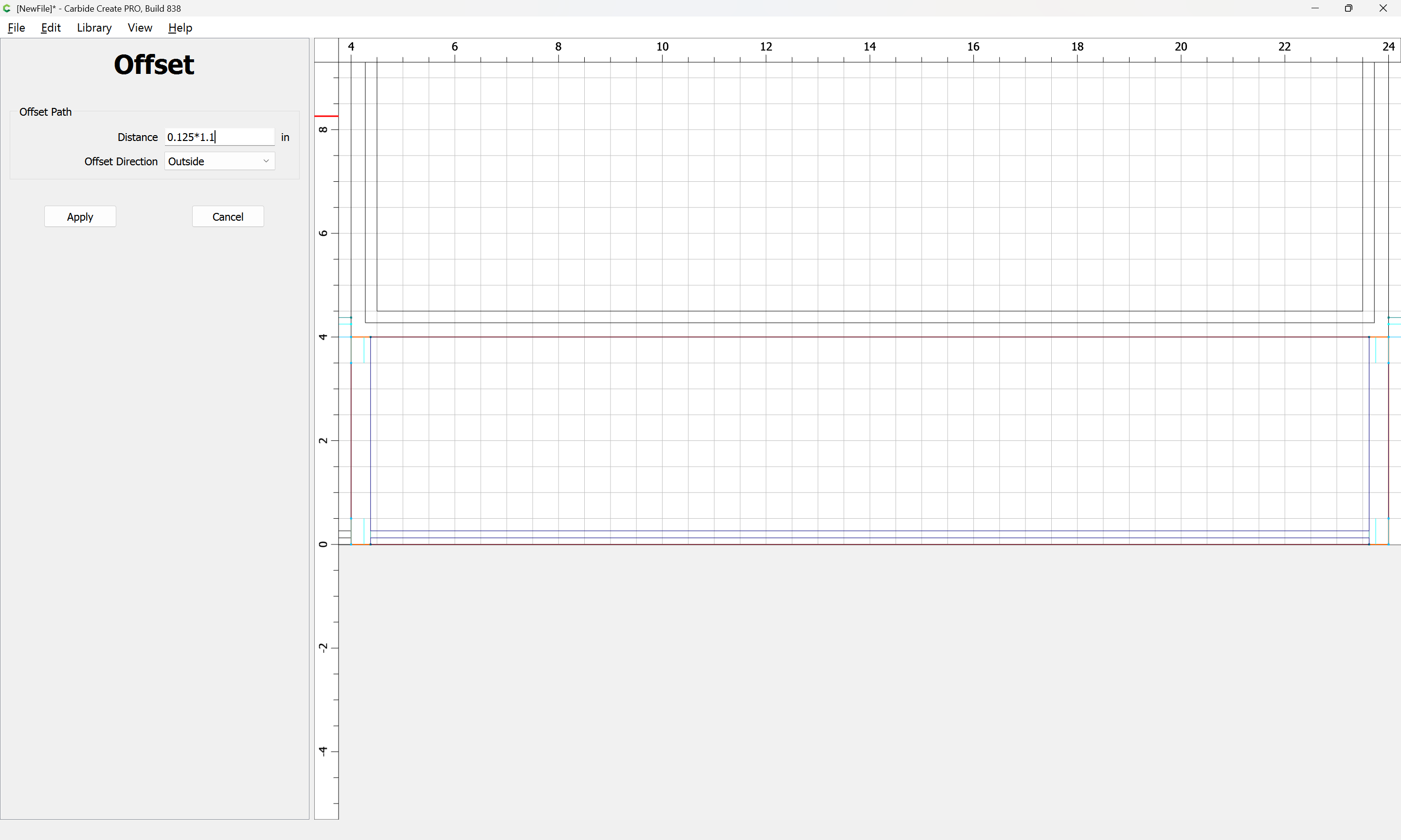
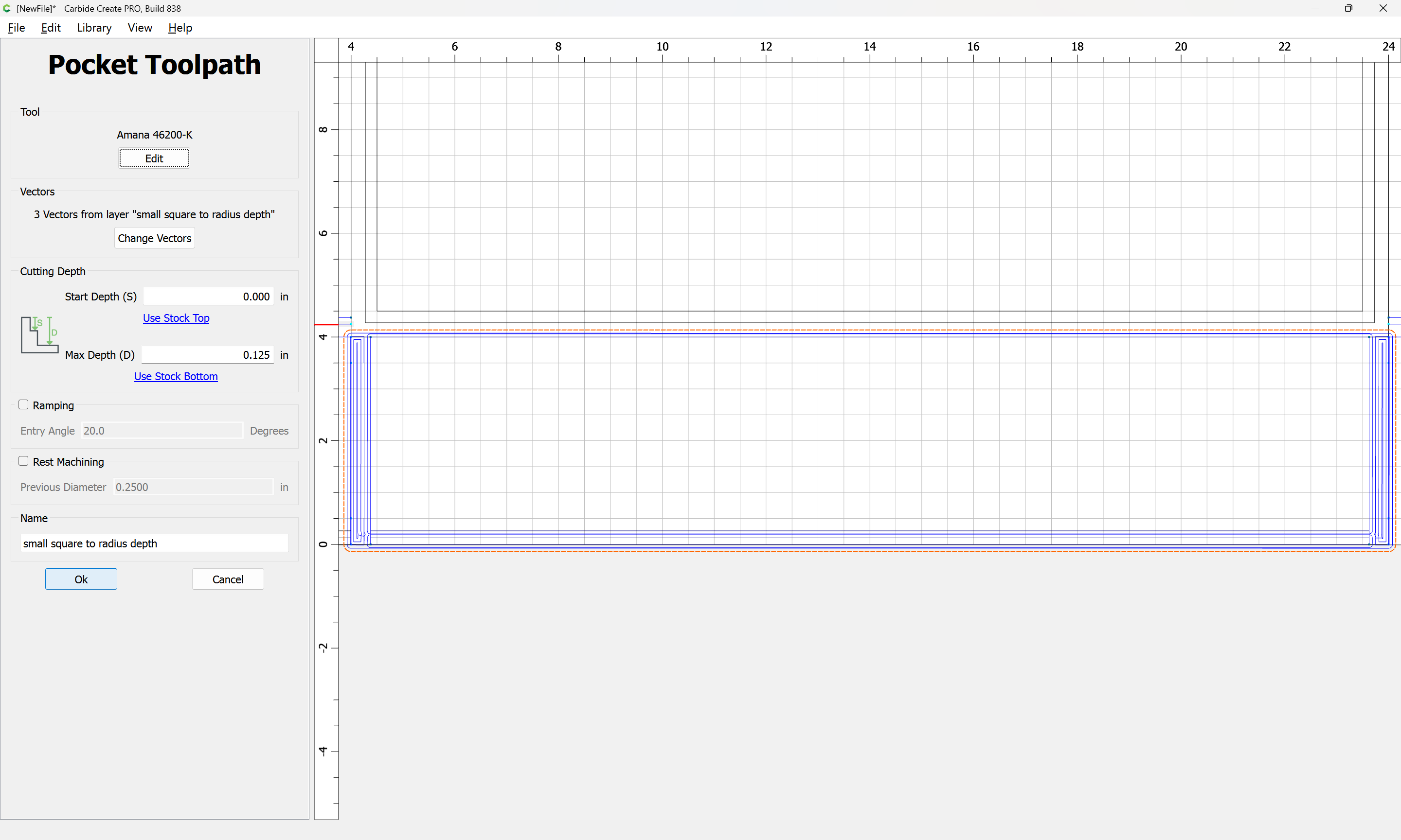
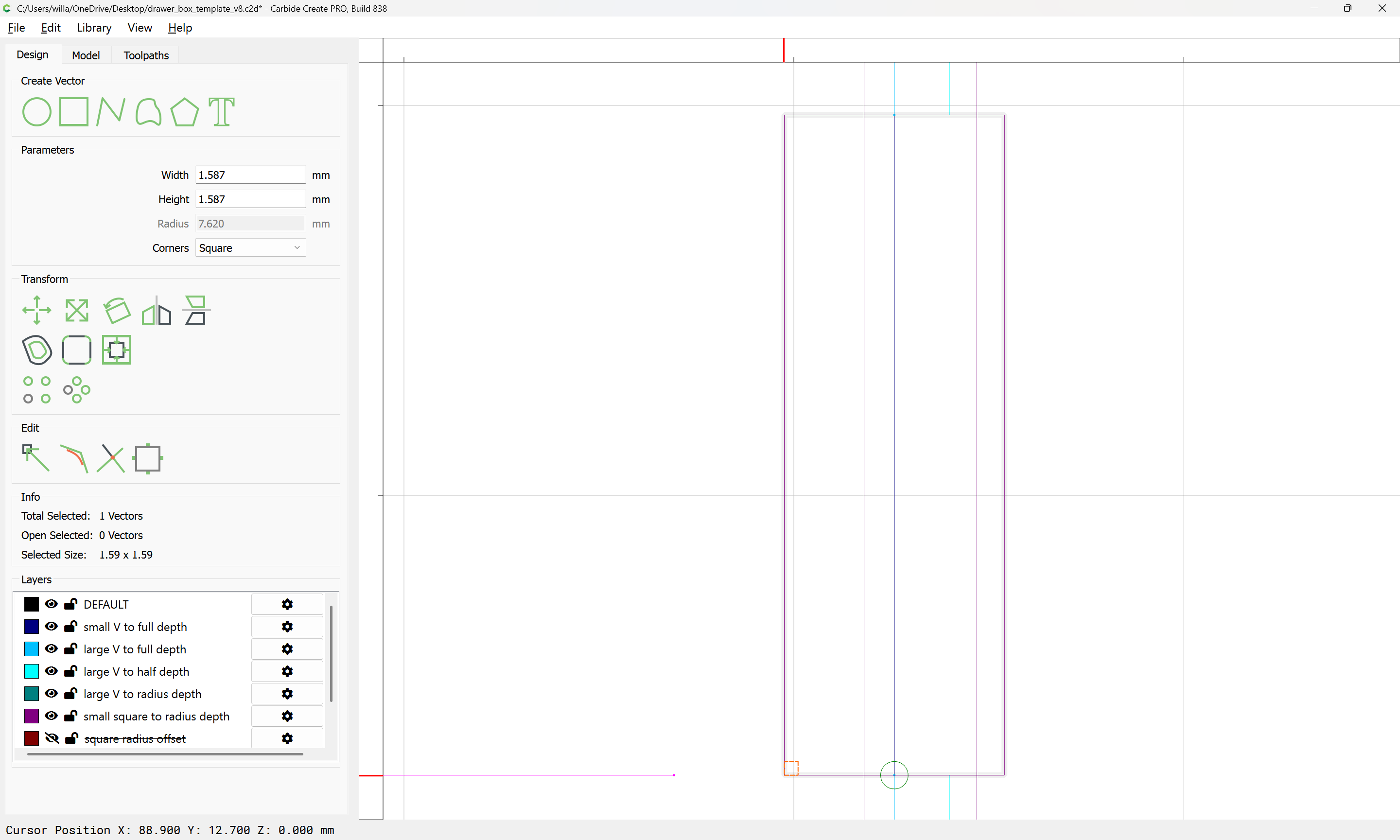
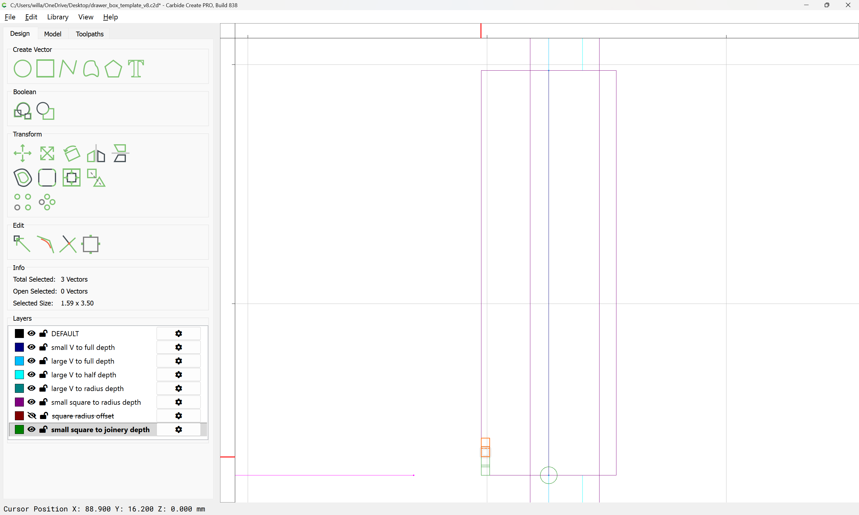
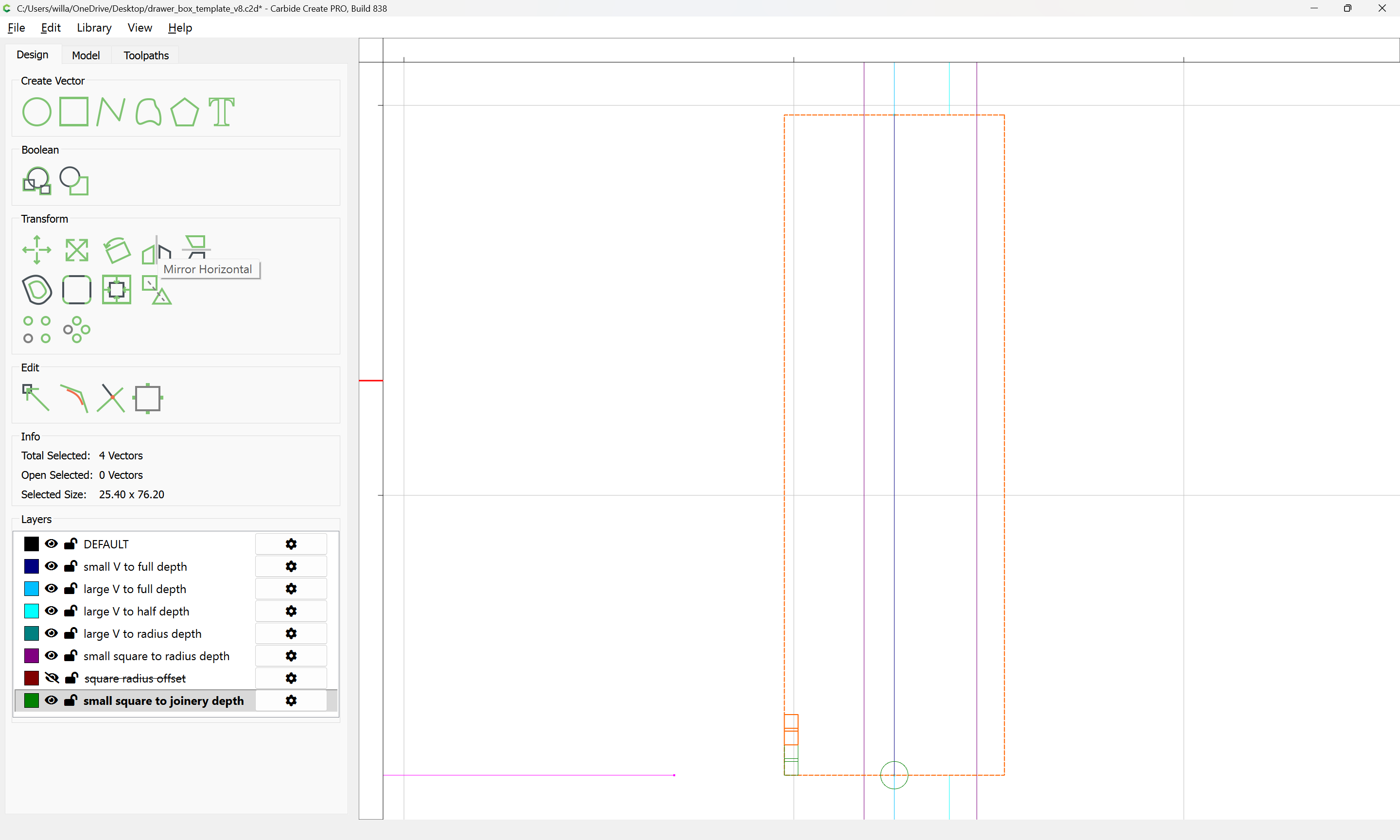
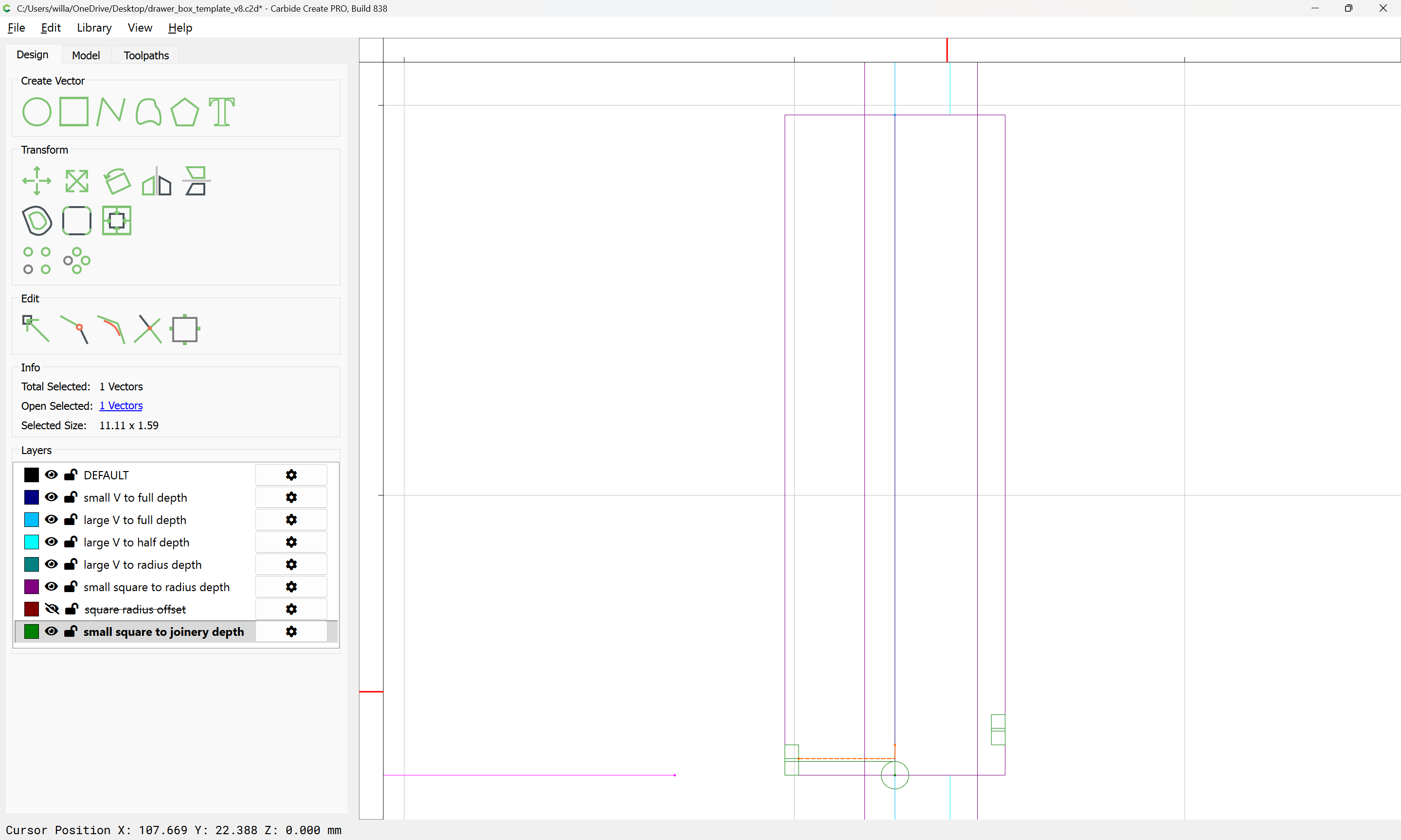
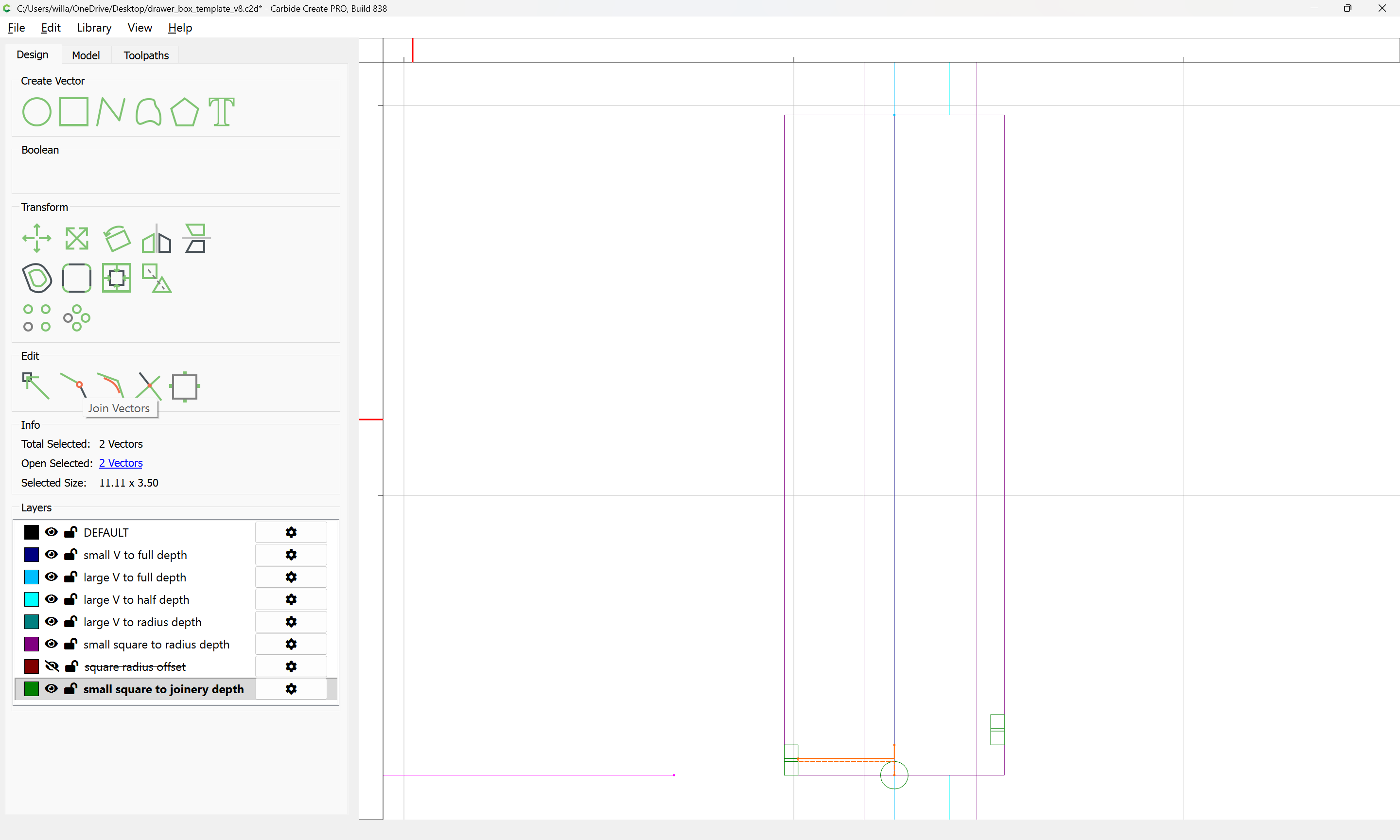
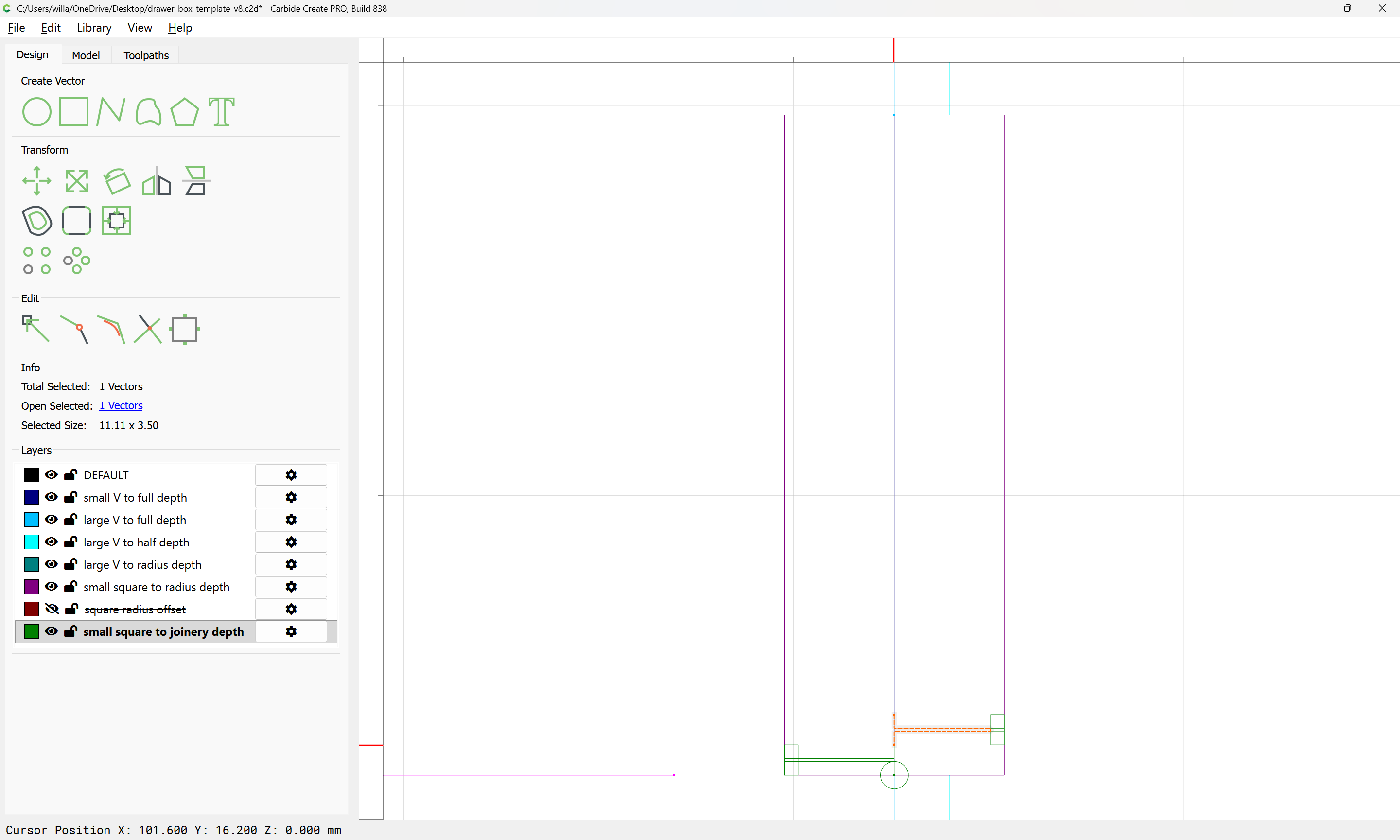
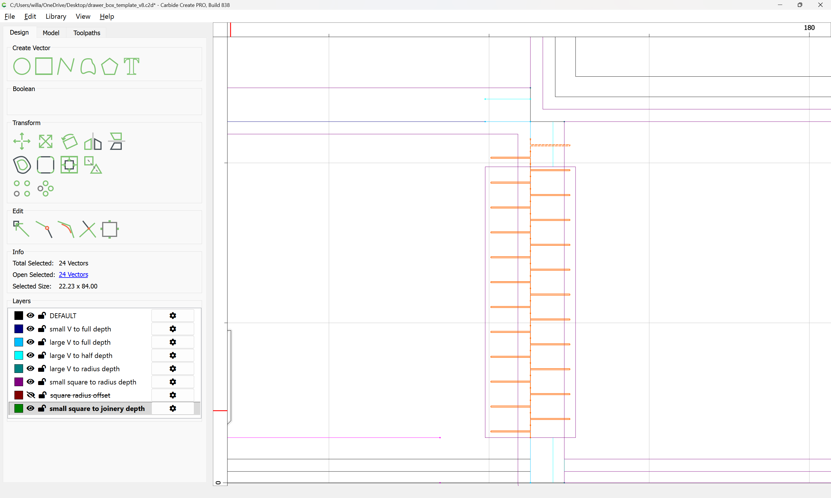
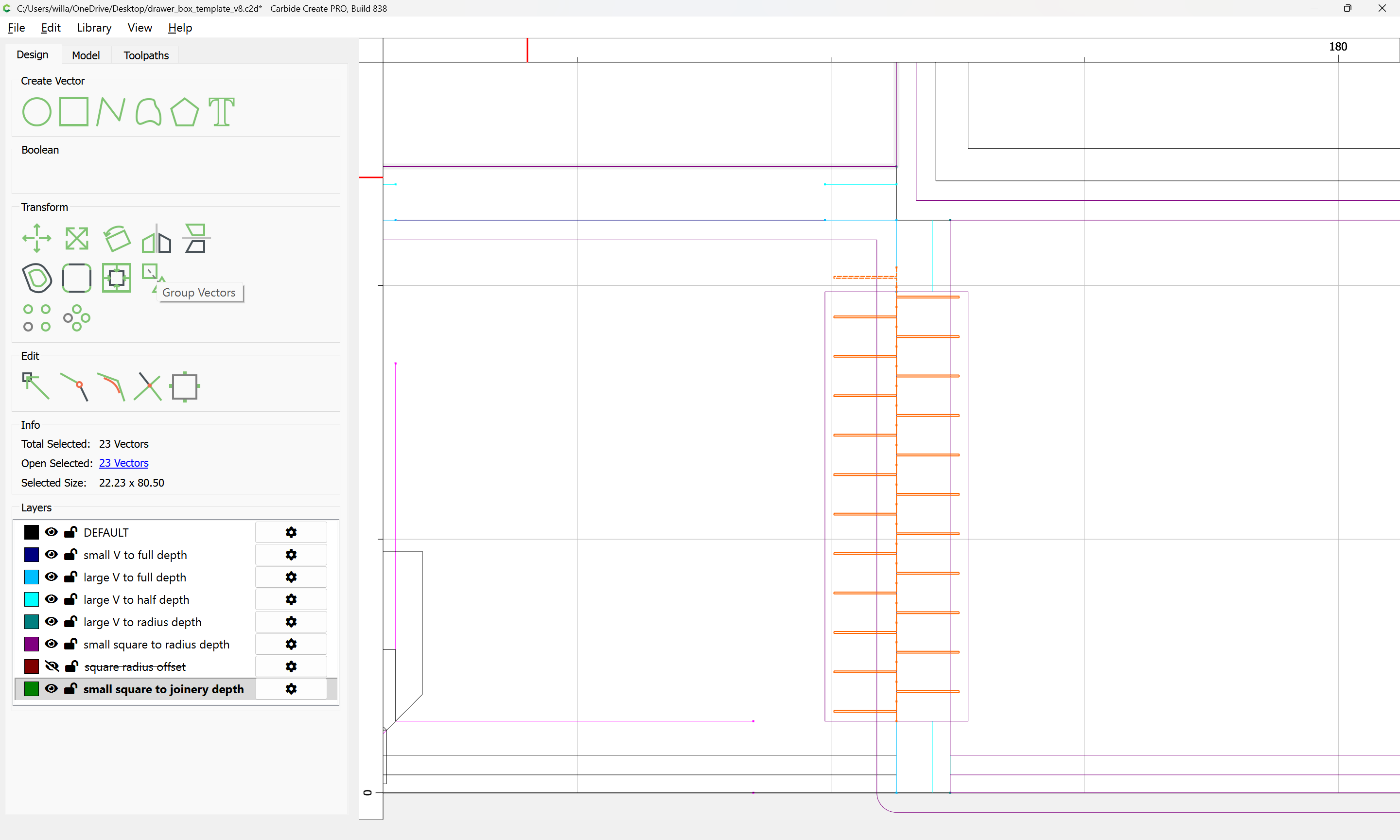
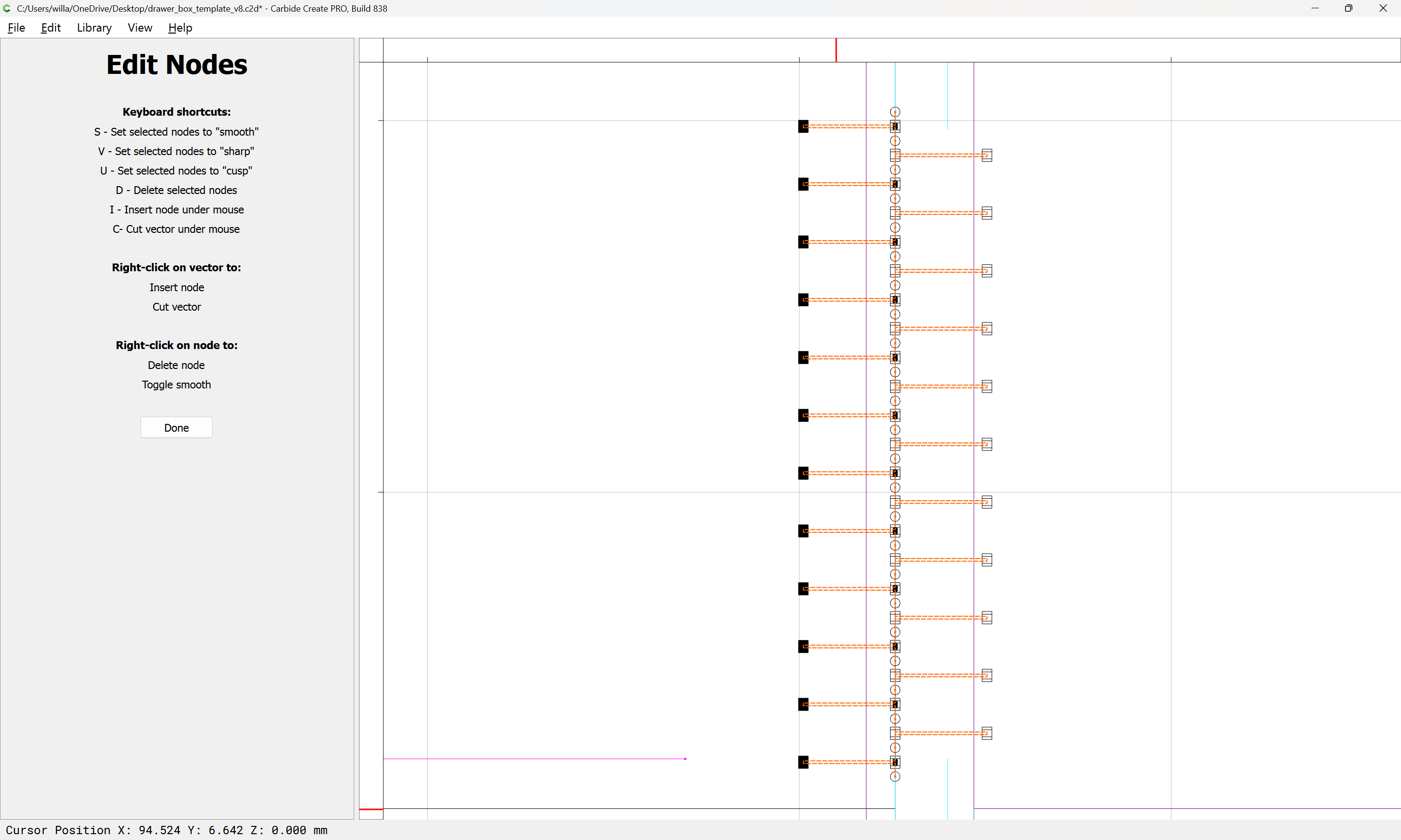
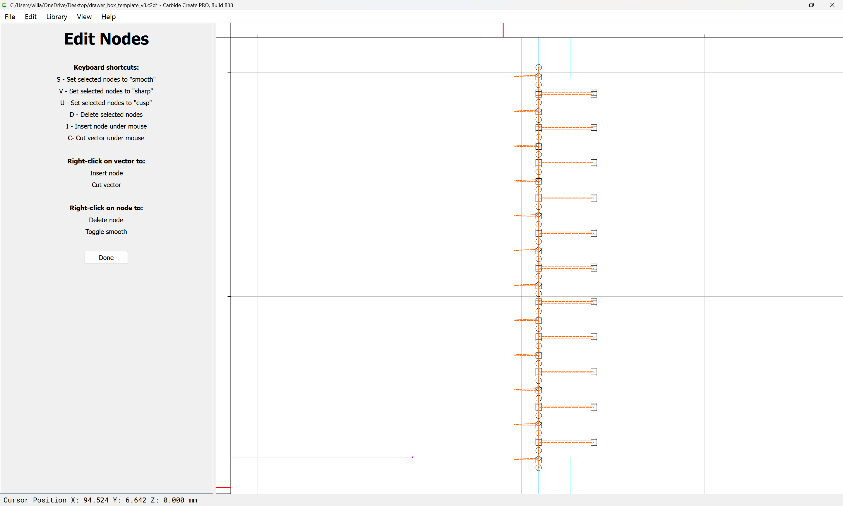
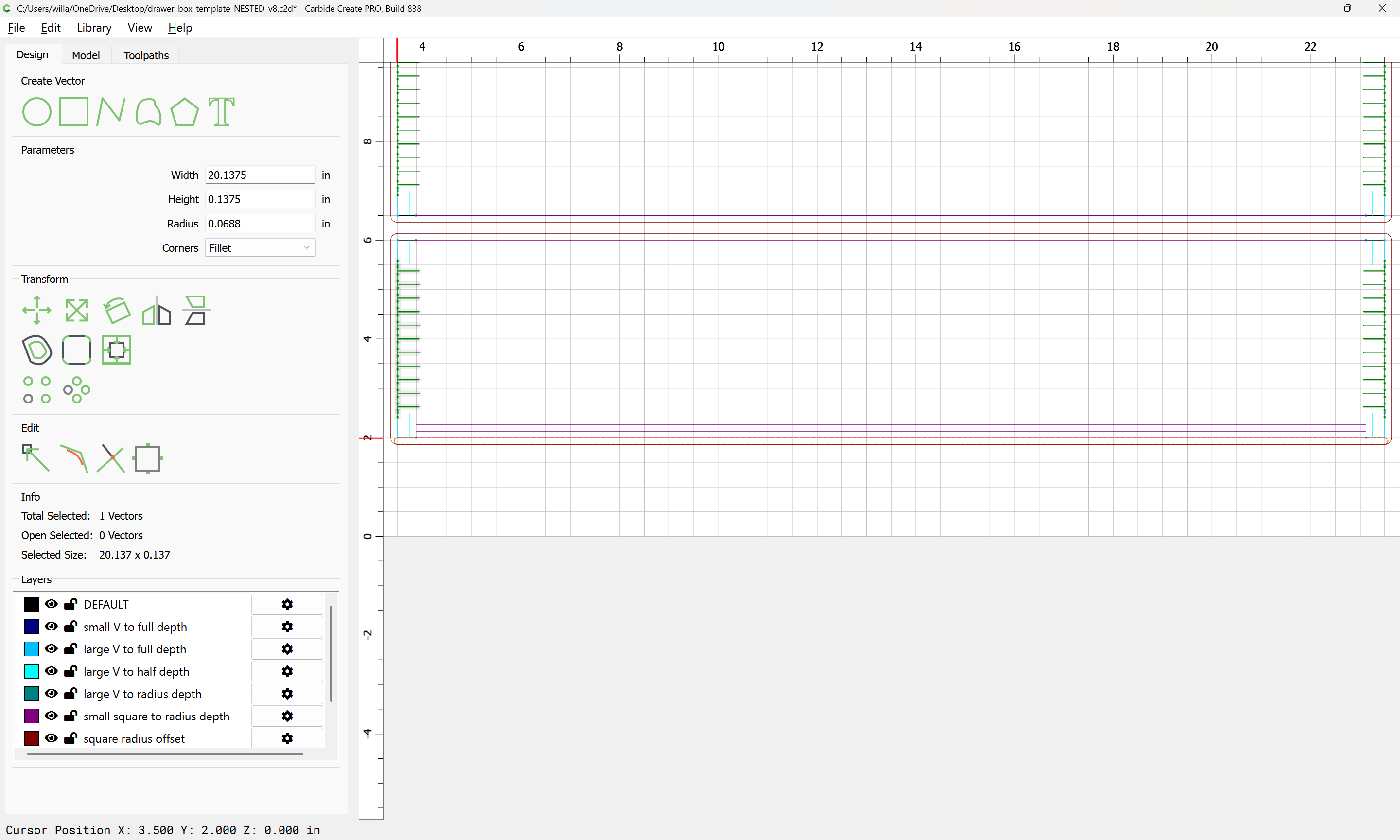
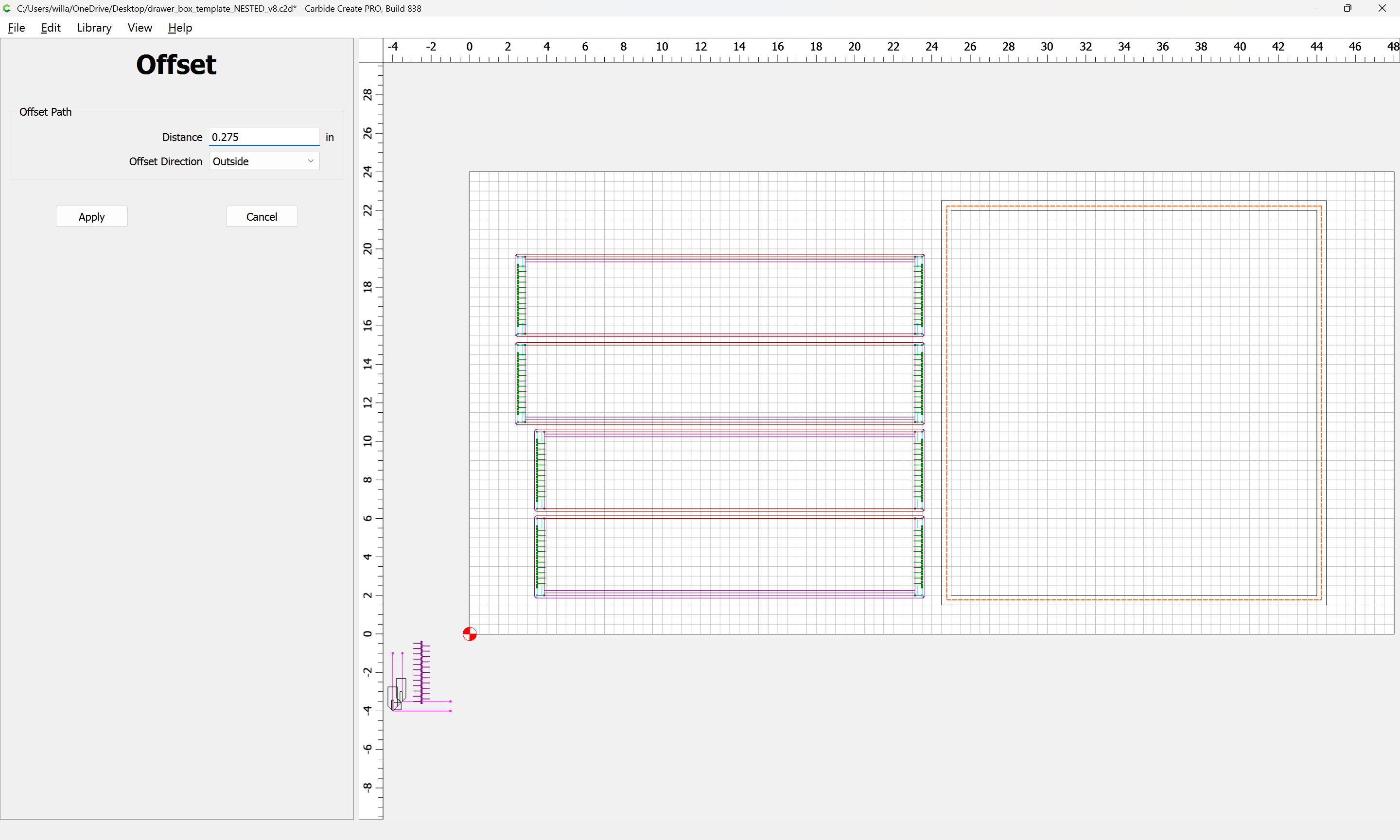
A slightly complex region which will need to be defined is the removal of material above the box joint “fingers” so that it will not be necessary to radius them, or to add dogbones which would remove material weakening the joint.
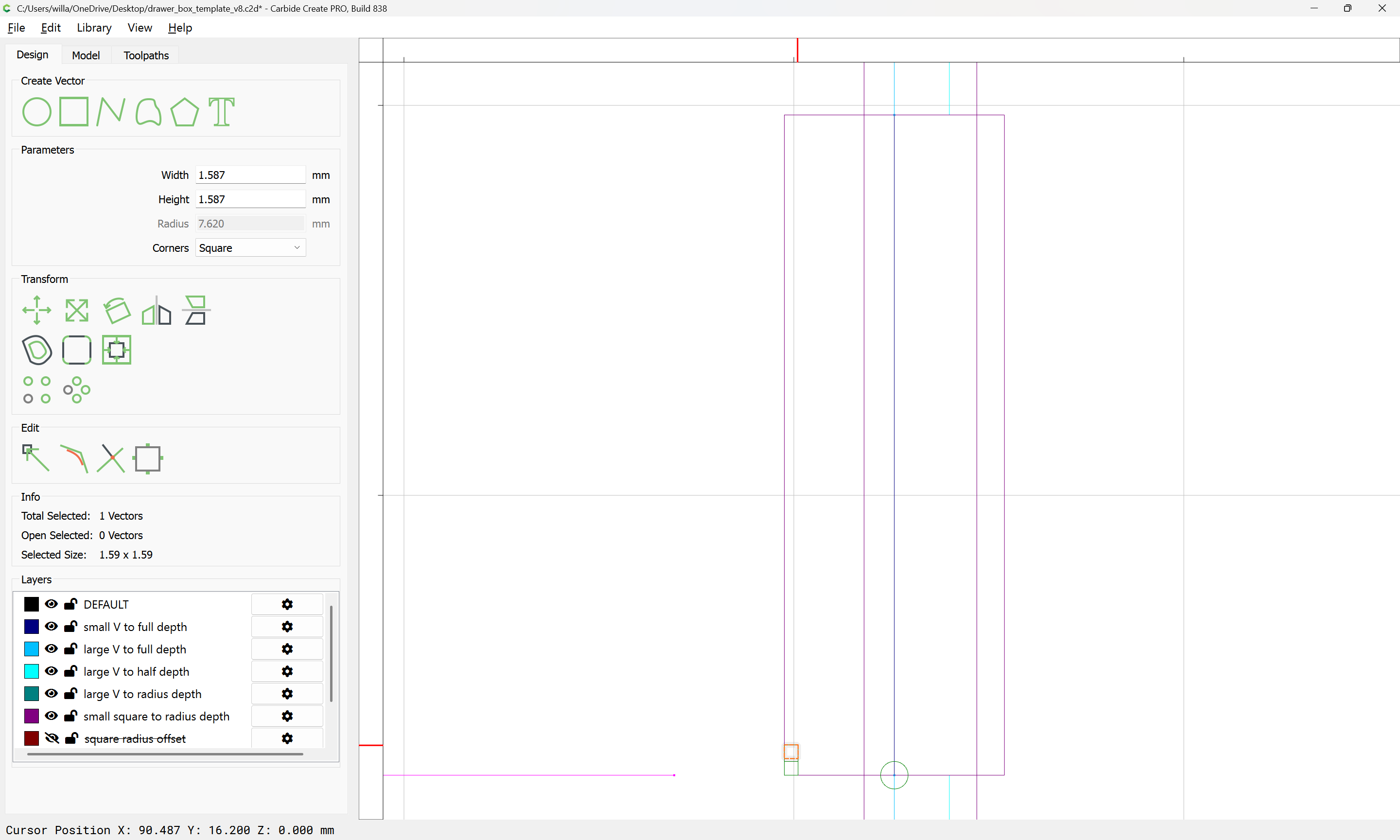
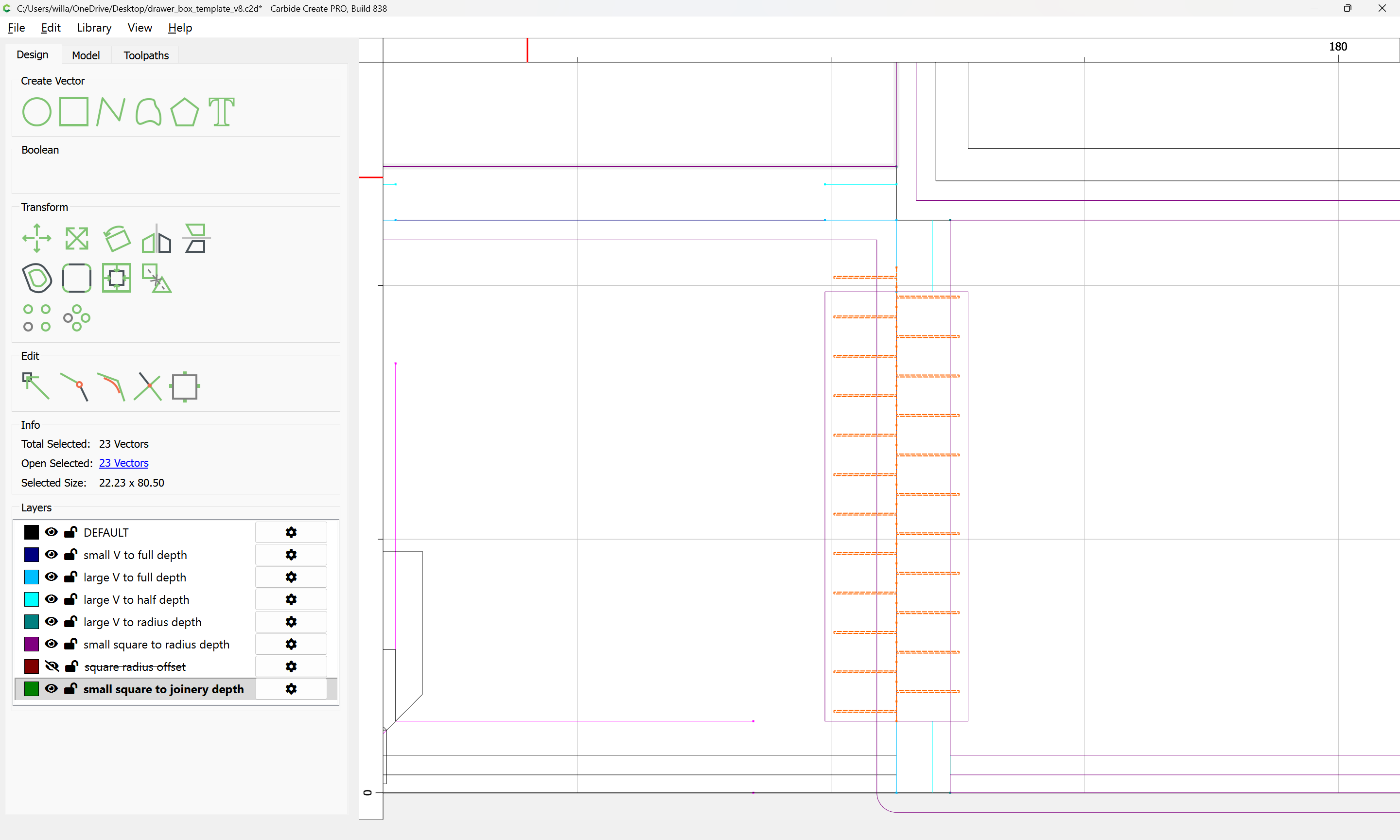
in such a way that the matching halves of the joint will fit together, but will not protrude beyond the extent of the effectively 45 degree angled cuts which make up the full blind miter.
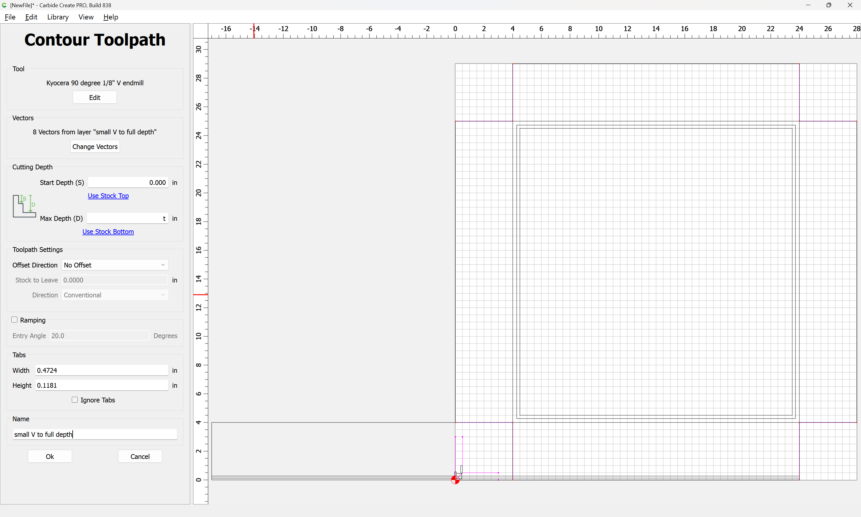
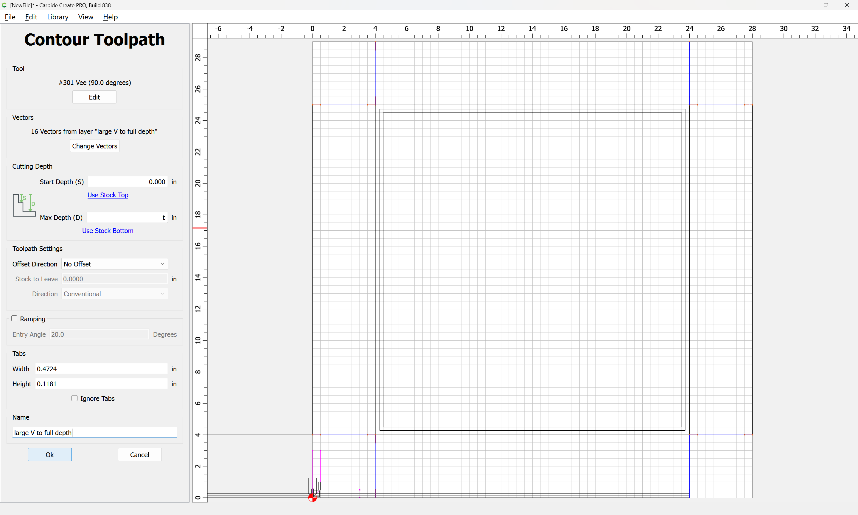
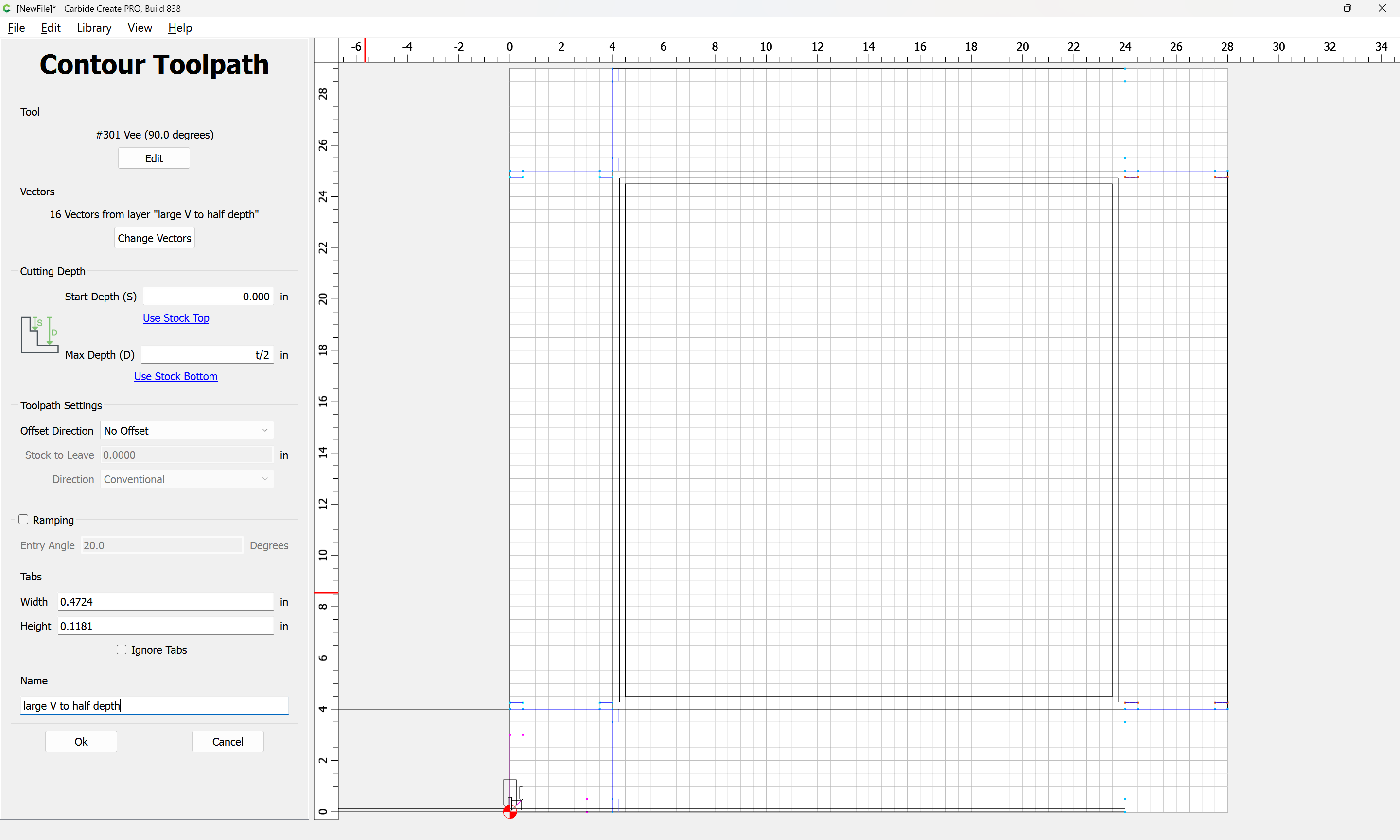
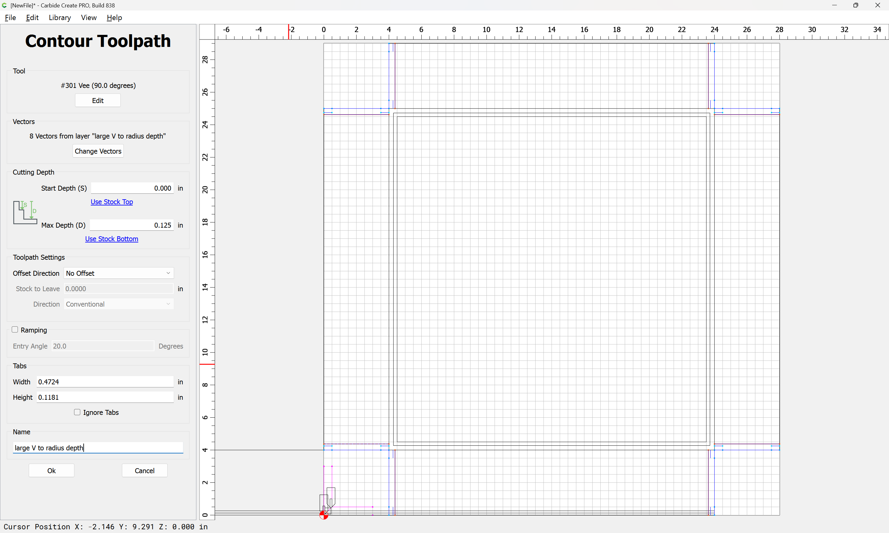
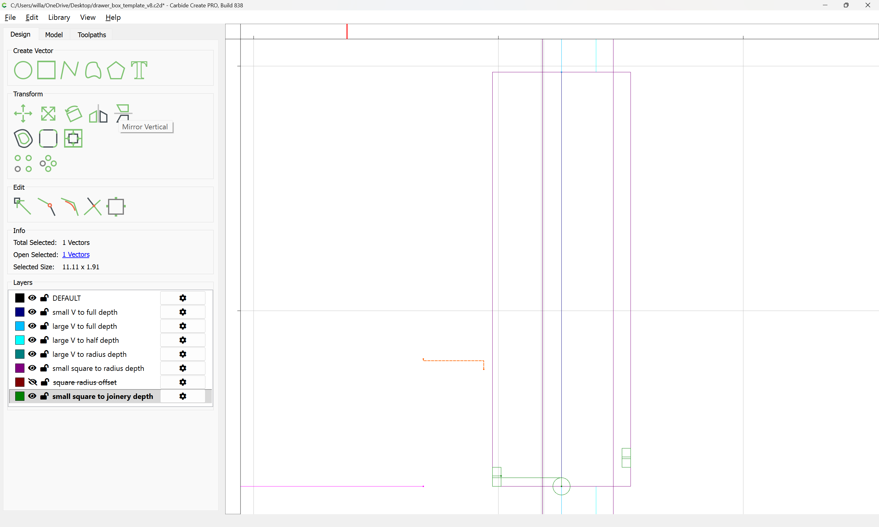
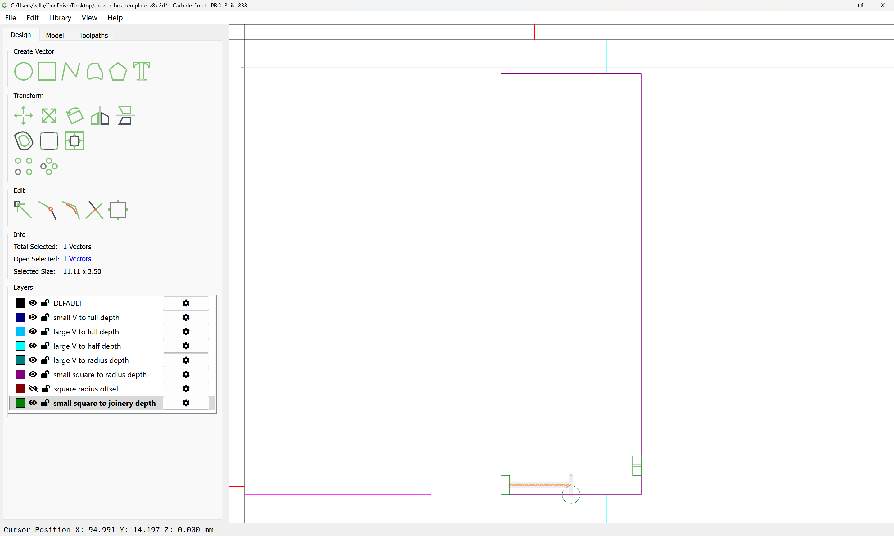
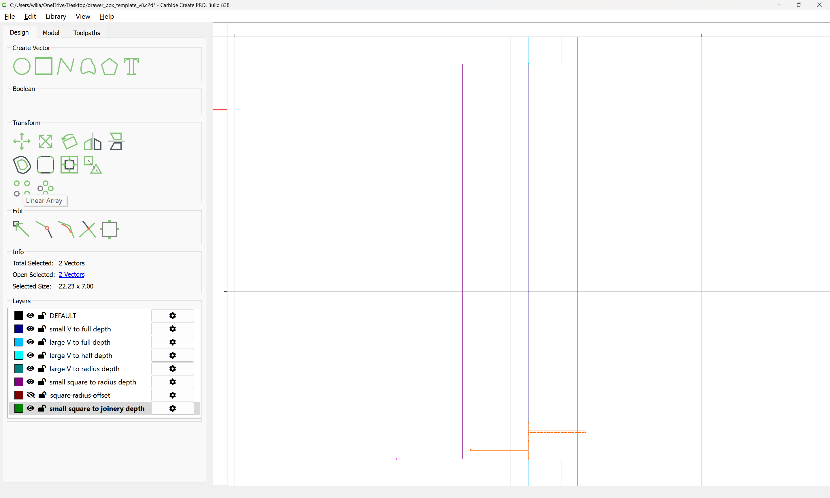
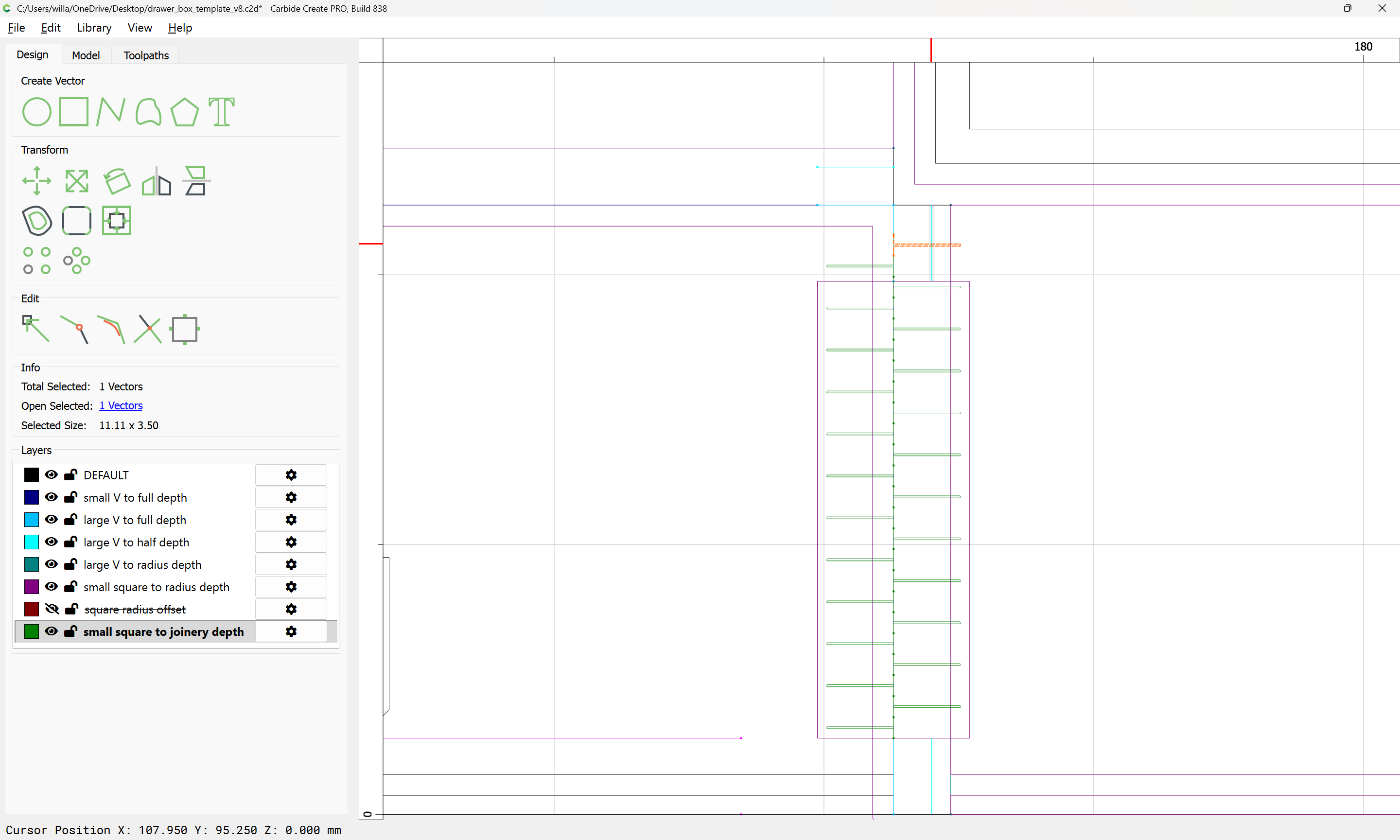
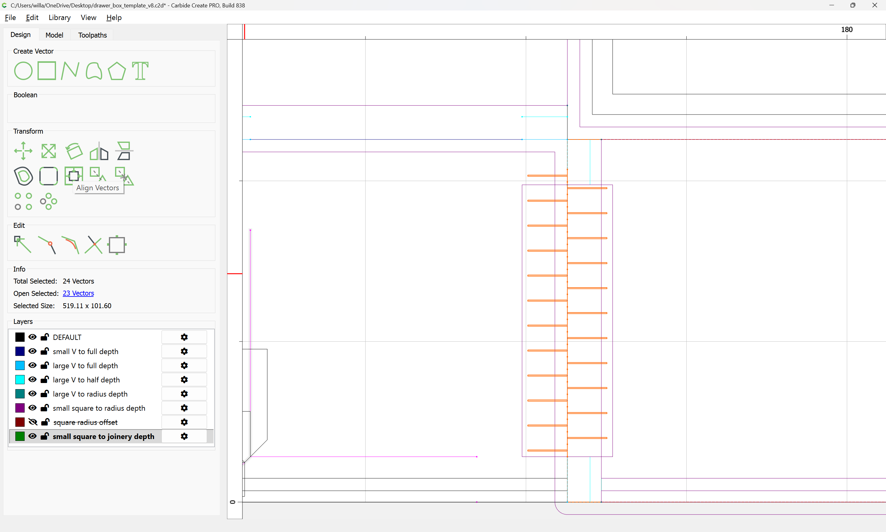
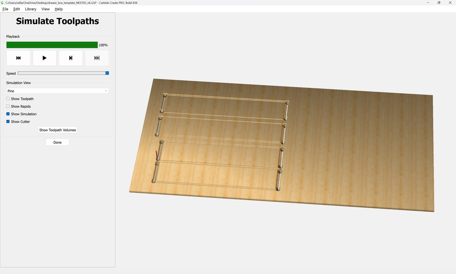
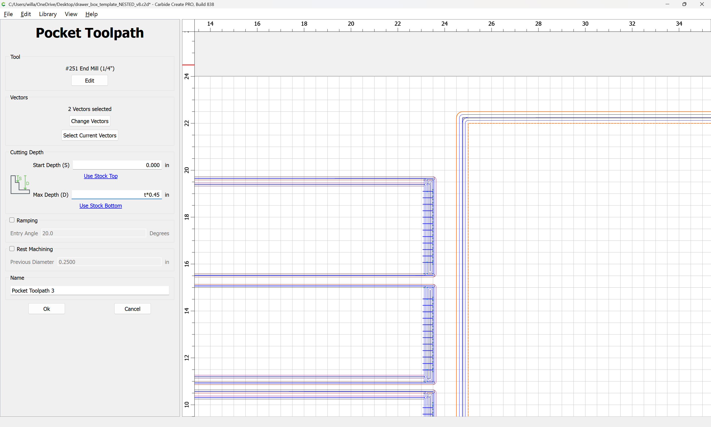
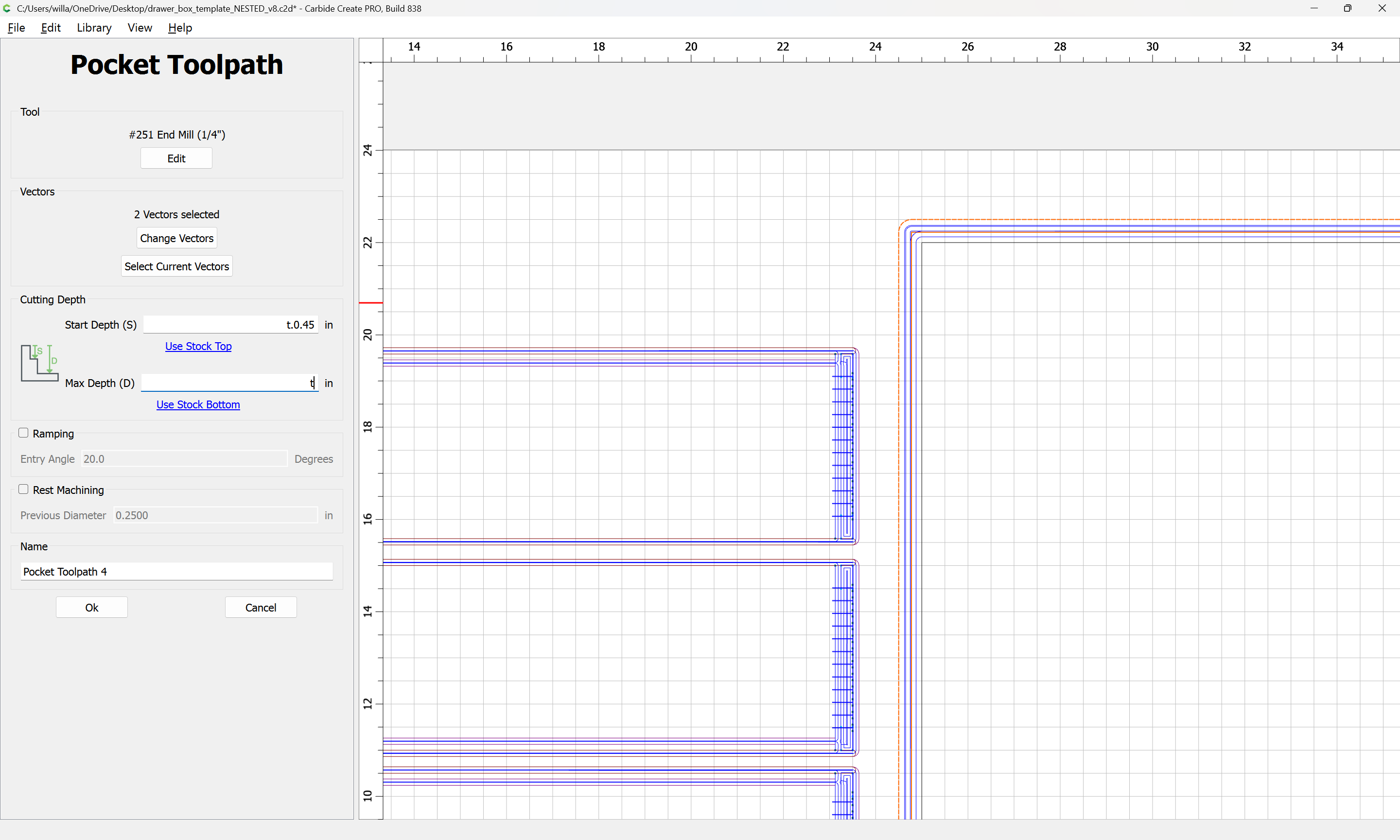
Lastly, the toolpaths will need to be arranged and ordered adjust for optimal material removal — in particular, the small V to full depth toolpath should be cut last and may have its Start Depth set to the bottom of the joinery depth toolpath.
For drawer joints in good quality plywood you can cut lock rabbet joints on the table saw or router table in a tiny fraction of the time. They are very strong, especially if you glue in plywood bottoms in the drawers. The lock miter joint is similar, but fussier to set up and make if you don’t want to see the joint at the ends
If you use Vetric Vcarve there are multiple drawer plugins that’ll calculate everything out for you and do a modified dovetail (since you are cutting from the side instead on vertical). You just punch in your drawer dimensions and it’ll spit out all the files and tool paths. There are cabinet ones as well, lots of support for this type of thing.
Just as an alternative. You can obviously do it with CC as pointed out above but if you want to just make it simple there are options out there.
That was the first drawer I ever made in my youth, many decades ago. No power tools or computers involved (yes, they HAD been invented!). I still like it.
I did all of my garage drawers (and even the cabinet) cut on the CNC.
An example is here: Easel - DeWalt cabinet drawers 16.25 x 20.75 x 4.25
wherein, i outfitted each DeWalt planer stand with four drawers. If this were my kitchen, I would do the same, but cut it out of real Birch Veneer (instead of Home Depot Sande Ply).
Using Easel, it takes only about 10 minutes to do the design, and about 30-45 minutes per drawer to carve. I was unable to do this using Carbide Create, without external tools.