Knapp Joint with CNC

It was the first machined joint — easily drawn up and machined as finger joints or dovetails are on a machine with a suitable fixture.

See:

for details on usage see:

2 Likes

Yes but I was wondering if anyone had tried a knapp joint since I think it is well adapted to the Shapeoko. No need to reinvent the wheel if already designed! A couple of weeks ago a member asked for joints adapted to the CNC, I was not aware of this type of joint and thought I would ask here.

1 Like

A parametric model here in fusion would be awesome.

Trivial to code one up in OpenSCAD.

I’ll add it to the list for https://wiki.shapeoko.com/index.php/Design_into_3D

2 Likes

Probably this could be translated into Fusion.

Start by defining the variables needed:

  • stockwidth
  • stockthickness
  • endmilldiameter:

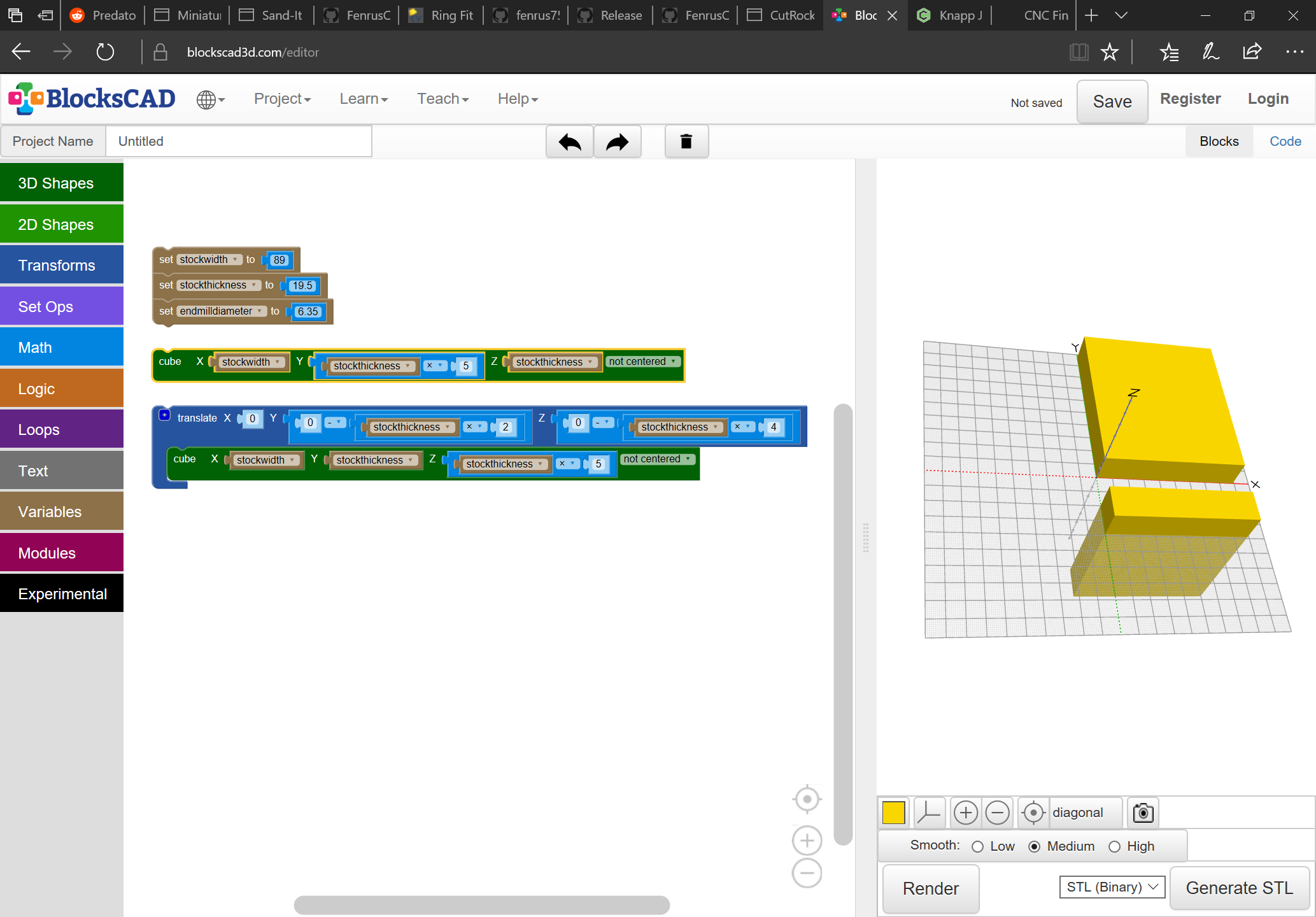
Next draw in two cubes sized and placed appropriately — you’ll need a fixture which holds one board on edge such as: https://cutrocket.com/p/5cb25f3380844/ — see: CNC Finger Joint Box for further details.

It will then be necessary to determine how many pins/scallops there will be — the minimum dimension here should be the endmill (it is left to the user to choose dimensions which will work, no error checking).

The number needs to be:

stockwidth / ( (endmilldiameter + 10%) * 4 )

rounded down — this is based on:

each unit will have:

  • central pin standing proud of the vertical board
  • a radius cut around that which allows the endmill to travel around the pin
  • a smaller radius allowing the endmill to return

Note that limiting this by/basing it on endmill diameter has the obvious negative consequence of precluding symmetry — probably it would be better to base on stock thickness and force the user to use a smaller endmill.

Actually, scratch that — my sense of æsthetics won’t allow that — instead, we back up and just allow two inputs, stock:

  • width
  • thickness

and everything will be based on those dimensions and it will be up to the user to source a suitable endmill, or select stock which matches what their endmill can cut.

Okay, re-drawing on that basis. We want:

  • central pin aligned along the horizontal center axis of the stock
  • larger area around that
  • endgrain for front blind edge
  • symmetrical area at other side of board

So we draw up:

and group it and size it to match the stock thickness:

hitting “Apply”

We will need an evenly arranged set of these, joined by semicircles, so we do the math:

stockwidth / stockthickness

rounded down will provide the number of units

then for the spacing we’ll need to get the remainder, divide it by the number of units and add it in-between

So that would be:

nou == round(stockwidth / stockthickness)

(n.b., that may need to have 0.5 subtracted to force it to round down)

Other variables which will be needed:

pindiameter == stockthickness / 4
covediameter == stockthickness / 2
covespacing == (stockwidth / (nou * covediameter)) / nou

It is possible that we may be off by one somewhere — we’ll have to see how the spacing and dimensions work out.

I have created a Knapp joint in VCarve, I will have to try to cut is later today.

1 Like

You’ll want to add some spacing in-between — the scallops are too sharp and won’t allow you to cut the matching part so that it will fit without a void — has to be rounded.

That’s what I’m working through now.

Well my first problem is that I need to create a jig to hold the vertical pieces. Second, I was thinking that I would use a first pass with a 1/4 in endmill and then a second pass with a 1/8in endmill to clear the scallops but I’m not sure it is required. The one I showed is based on this video using a 1/4in bit in a Pantorouter. Hard to beat the speed of the pantorouter but no need to make a template with the CNC.

1 Like

Fixture, not jig — a fixture holds the work for the tool to be presented to it, a jig guides the tool when the tool is presented to the work.

Design at: https://cutrocket.com/p/5cb25f3380844/

1 Like

We’ll want a loop (may be off by one and other formulae above may be off — will adjust later), and the loop will need to be wrapped up in a difference with the object we are subtracting from:

With a bit more code we arrive at:

halfway there — just have to do the opposite

Re-using and re-arranging it we arrive at:

Changing parameters works:

(and I fixed the extraneous bit on the left)

1 Like

Will, does this generate GCode or do you have to import STL and create toolpaths?

You can export an STL from OpenSCAD which should then be machinable in MeshCAM or some other 3D CAM program.

Another option would be to add some geometry and then export a DXF which would be ready to import into Carbide Create for machining.