Quick project to share with you. Well, the project wasn’t quick but the post should be… I hope this is the correct location for this type of thing.
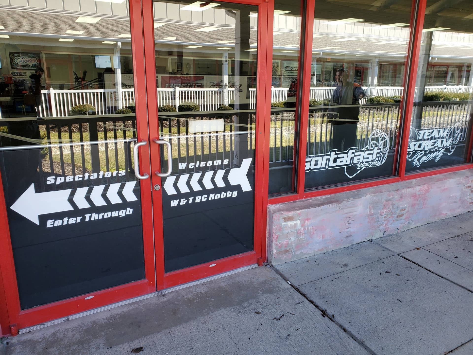
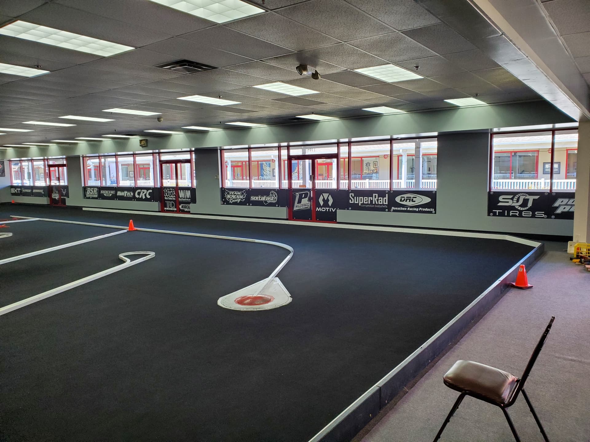
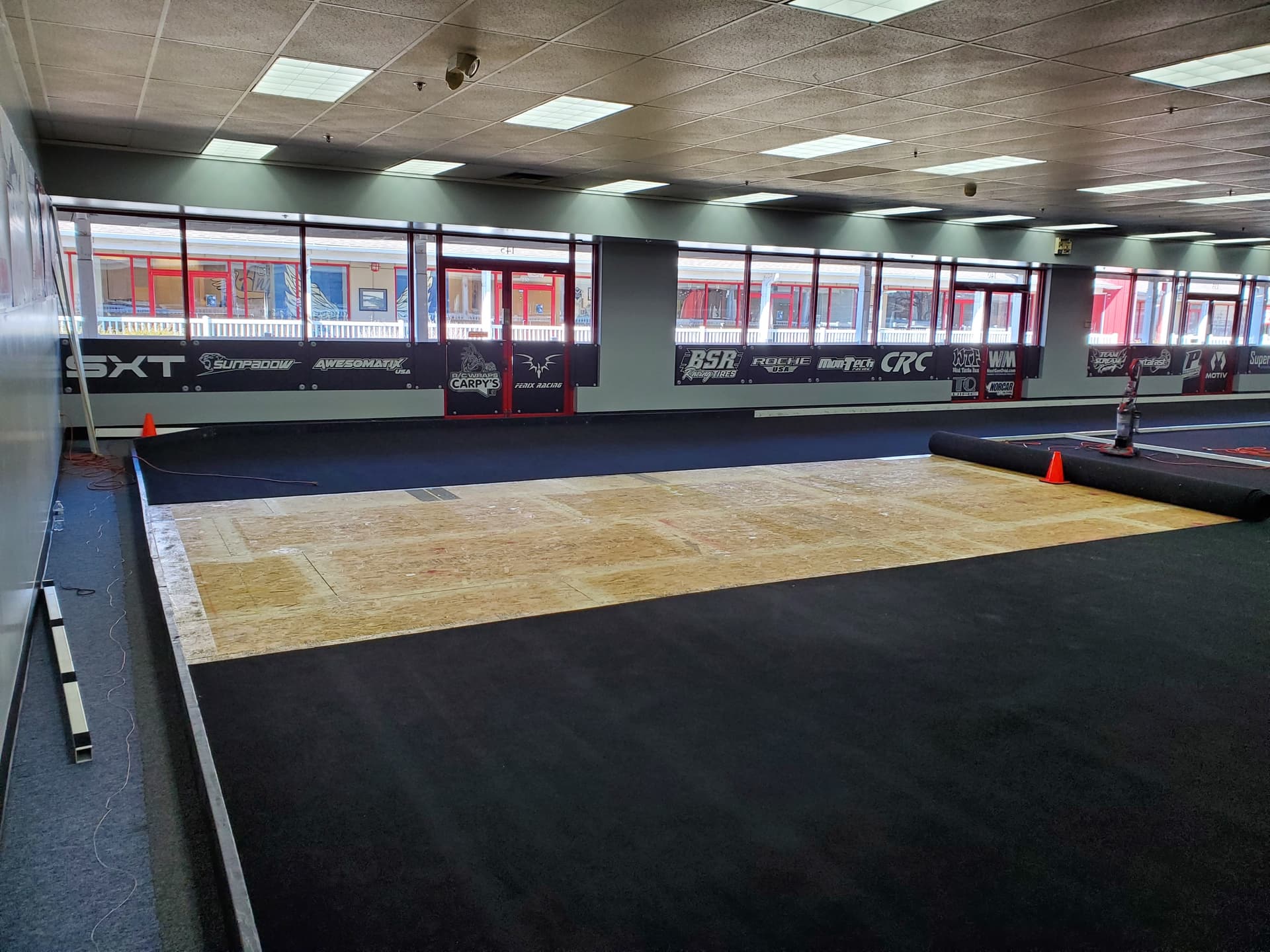
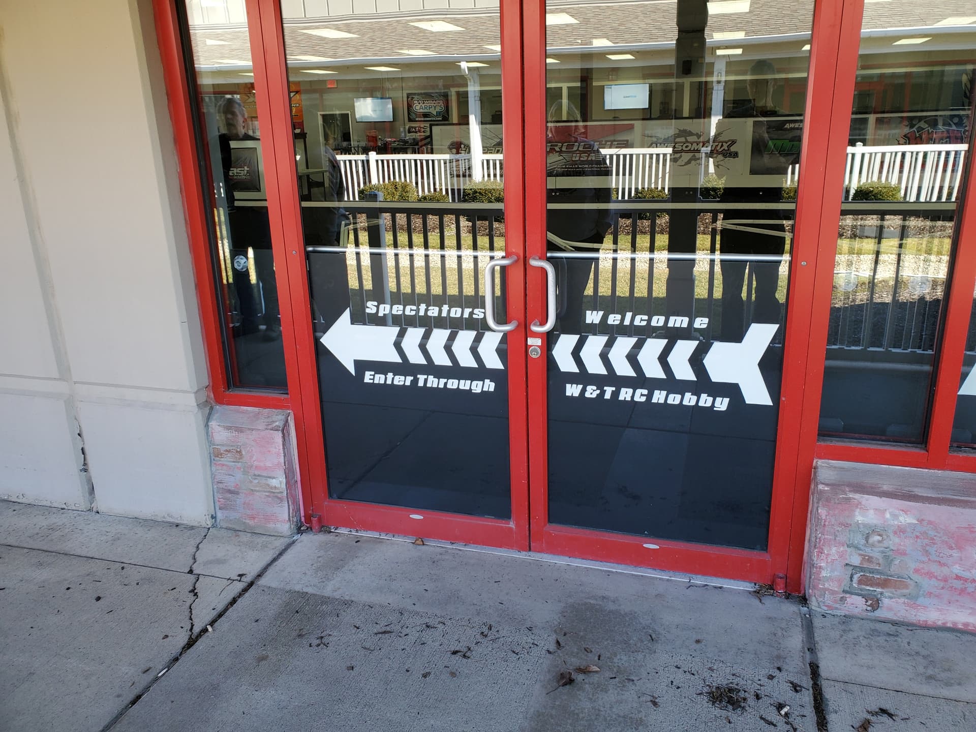
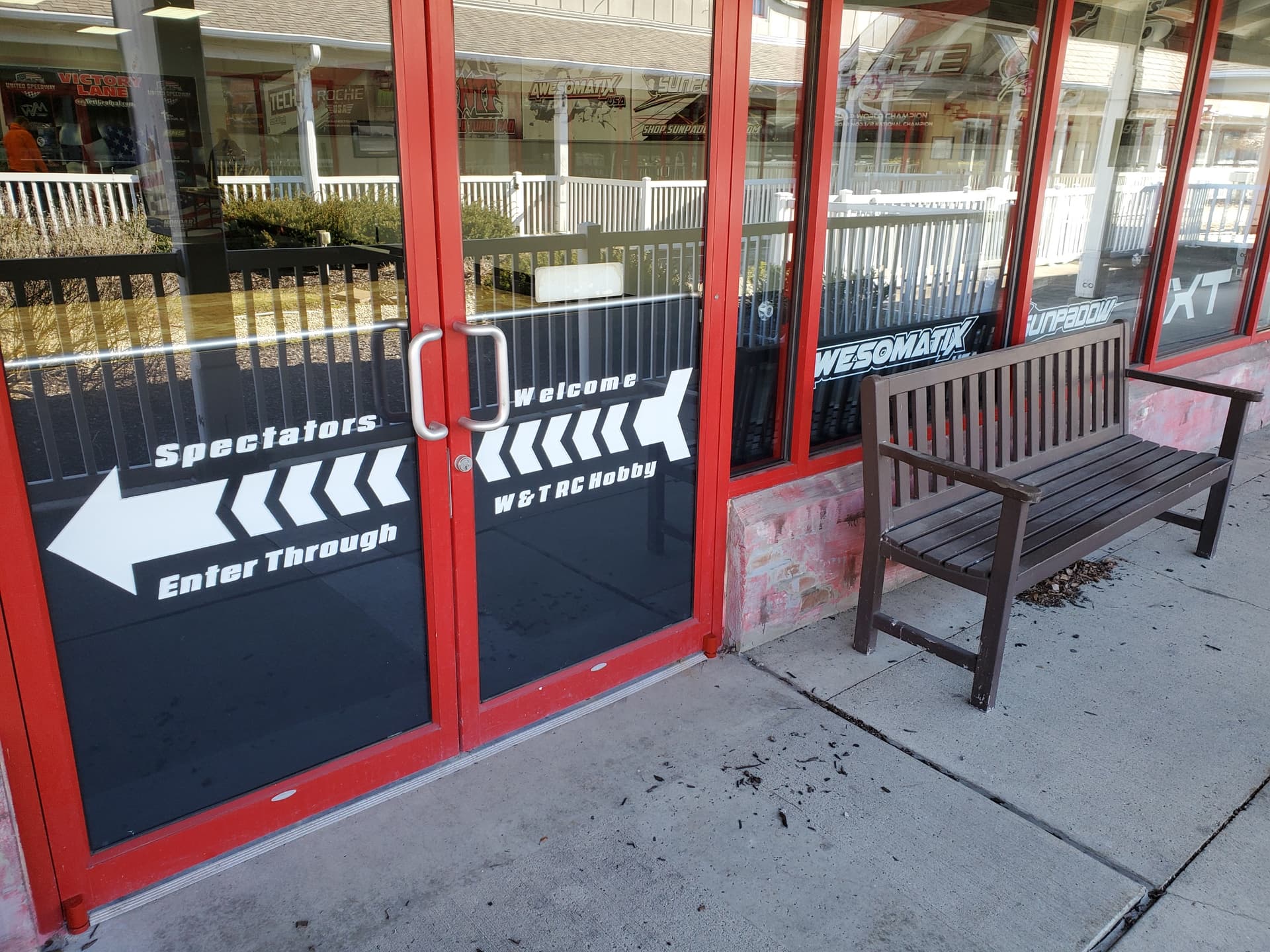
Anyway, a local RC club asked me to come up with a “catch fence” to protect the windows at their new location. Some ideas were discussed including banners and plastic lattice ETC. Well, having a CNC and knowing I could do better I decided I wanted to carve track sponsor logos out of MDF panels and make custom brackets to attach them to the window mullions without holes.
Here is the final results. 19 total panels. All two sided. 1/2 MDF 1/4" 3 flute end mill (all I had) .100 depth of cut 120 in/min. 90* v-bit, .200 depth of cut 90 in/min. Large panels are .200 deep. Door panels are .150 deep. On those I did a .150 cut on the 1/4 but slowed to 90 in/min.
Hand painted. Being hand painted they are best from about 5’ and greater. Closer than that and you see the flaws (or at least I do).
This was my first real project on the CNC and my first with tiling toolpaths. Used Vetric VCarve Pro for the artwork and tool paths. As you can see I could not drill dowel holes so instead I drew up a 24.5" spacer in Carbide Create and machined it on my Shapeoko. Then I used this spacer when I moved the panels for the tile 2 operation. Worked perfectly!
All done on a Shapeoko 3 XXL. Larger panels are 24" x 49" and the door panels are 30.5 x 39.5.
Thank you. Everyone at the track when we installed them seemed to like them.
The edges aren’t as crisp as I would like up close, but lessons learned. They look perfect when viewed at any kind of distance.
As for the spacer let’s dig into that a bit.
First, we need to baseline the machine. You may have done this already, but I wanted to be sure everyone knew the full process. So basically, I have a “proofing” file I created in CC. It is three shapes, one square, on diamond and one circle, all 2" in size. I run this file from time to time to be sure my machine is machining at the set sizes for all various possible moves. Essentially, it tests for any backlash issues etc. If the machined area isn’t 2" then we have work to do to get the machine working as it should. This step is critical since when machining the spacer, we can’t introduce any backlash errors into the piece, or our tiling tool paths won’t line up properly.
Next up we have the file for the spacer. Well, first I determined what my spacer length needed to be. I chose 1/2 my panel or 24.5". I created a quick rectangle in CC with a height of 24.5" and a width of 1.5" (1.5" was just a dimension based on the material i had to cut the spacer out of). I then secured the stock to the bed using two holes I manually drilled into the stock. This allowed me to machine all the way around the material. I also included a quick v-carve with the 24.5" spacer text on the length… because I can… So, a quick machine up of the spacer and I was ready to create the fence and back stop. Note I set the spacer length I cared about in the same axis as I was tiling (Y axis for me).
Speaking of the fence it was just a piece of plywood I ripped about 4" wide on the table saw (it was actually a cutoff I had from another project). I attached a larger piece to the rear most portion of the fence. This allowed me to attach the backstop. I made the backstop the same width off the fence as the spacer so as to not introduce any possible error due to a un perfect factory edge on the MDF. Basically, the backstop and the spacer engaged the stock at the exact same spot. I’ll see if I can get a pic of the fence for ya.
Last up was to indicate the fence into the machine. Now my bed has a grid machined into it so I can get the fence super close without indicating it but for tiling super detailed signs I thought it best to indicate it in. I used the “STD” paper method to pickup the two end of the fence. I used the readout in CM to verify that my fence was indicated into the Y travel of the machine. After all that we are ready to machine so let’s jump into that process. Oh, I spot checked the middle after getting the ends in just to be really sure it was “good enough”.
Load panel into the machine and slide it parallel to the fence until is lightly contacts the backstop.
Secure the clamps
(Only needed for the first panel) indicate lower left corner and set Z height
Load tile 1 file into CM
Run first operation in T1
Change tool - FYI the Bit Setter is worth its weight in GOLD here. Especially for 19 two-sided signs each with two tool paths!
When T1 is complete loosen clamps and slide material forward about 26"
Insert the spacer parallel to the fence and against the backstop
Slide panel back until it lightly contacts the spacer
Tighten the clamps
Load tile 2 file in CM
Run toolpaths for T2
Flip panel and repeat (on most signs)
I hope that helps. If anything isn’t clear, please let me know.
Sorry for the long probably over complicated reply. I just wanted to be sure anyone who read it knew what involved in getting this approach to work properly. I didn’t want to assume all who would read it would be experienced operators.
Hope it helps!
Chris