Is this board salvageable or should I replace it?
I have a Shapeoko3 with a JTech 2.8 laser. I was moving the machine and was planning to clean it up and by accident the two wires from the laser broke off the Carbide Motion v2.4e board.
As I remember I had a hell of a time to solder the two very thin wires onto the board. It did not look pretty but my soldering was holding up for the last three years.
At that time when I had to replace the original board nobody told me that I can buy pins and solder it in from the back so I could plug in my laser. (Though, nobody mentioned to me that the laser head had a plug! or that I could actually get these pins from Amazon]. I read in one of these forums that you cut off the plug from the laser and solder the wires directly onto the board. Now how hard is it to clean out these tiny holes for re soldering of the new pins?
I attached a picture of my board. I can’t decide if I should just get a new board or try to fix this one! Any helpful tips or advice would be appreciated!
Hi @franazzo,
Did you forget to attach the pic in your post ?
The PWM signal used by the laser is actually available at several places on the controller board, so definitely don’t get a new board just yet, plugging it elsewhere might do it.
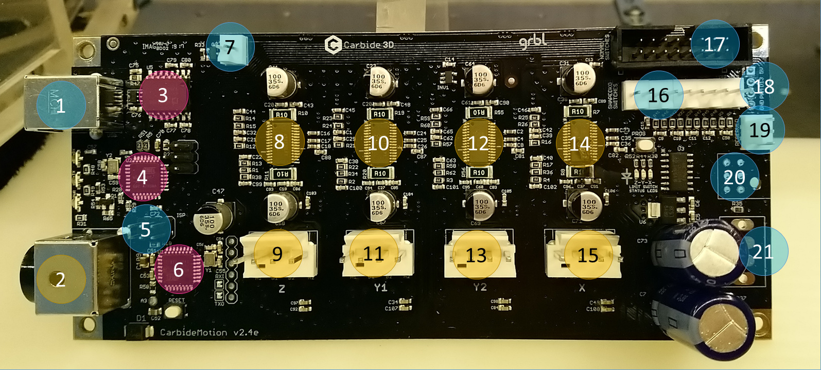
The PWM is available at #5 pins, #18, and #20
See this for detailed pinout at these locations
I suppose you had it soldered at #18, the easiest if you don’t want to fire up the soldering iron again (and trust me I have been there, messing up solder joints and not wanting to do more damage…), I would recommend just using two female dupont connectors to pick up the PWM and GND signals on the header pins at #5, no soldering required.
You can use a desoldering tool and clean it up
Hi Julien, no I could not figure it out how to insert a picture!  Can you tell me how to insert the picture file. I do not see the insert attachment anywhere!
It’s the icon with the small up arrow
Hi Julien,
Sorry I can not find how to insert a picture!! Yes you are right the wires were attached in picture # 18.
And yes I tried to clean it up and I am worried that I might have done some damage!
I assume that I can buy the female connectors on eBay or Amazon?
Thanks
Get some female Dupont wires off Amazon, like those
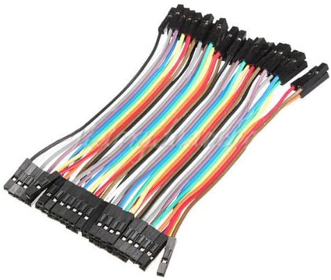
You’ll need two, plug female ends to #5’s middle pin of the top row for PWM, right pin of the top row for GND, and the connect the other ends to your laser.
Thank you so much, i will get this connectors.
Hi Julien,
I just want to let you know it worked beautifully with those connecters. I wish I would have known that when I replaced the old board!
I don’t know if you can also help me with another problem? Before I could test the laser I tried to jog the X-Y-Z axel and the Y&Z are working fine but the X axel is not moving and it makes a unpleasant sound! Am I wrong when I read the info you have sent me:
9 is the stepper connector for Z axis
from left to right pins: A1/B1/B2/A2 motor signals
#10 is the stepper driver for Y axis motor #1
#11 is the stepper connector for Y axis motor #1
from left to right pins: A1/B1/B2/A2 motor signals
#12 is the stepper driver for Y axis motor #2
#13 is the stepper connector for Y axis motor #2
from left to right pins: A1/B1/B2/A2 motor signals
Should all of the wire colors be the very same order as above ?or not?
The colored wires on my board are all over the place and not in the same order.
Should I change them over? Also what is A1/B1/B2/A1?
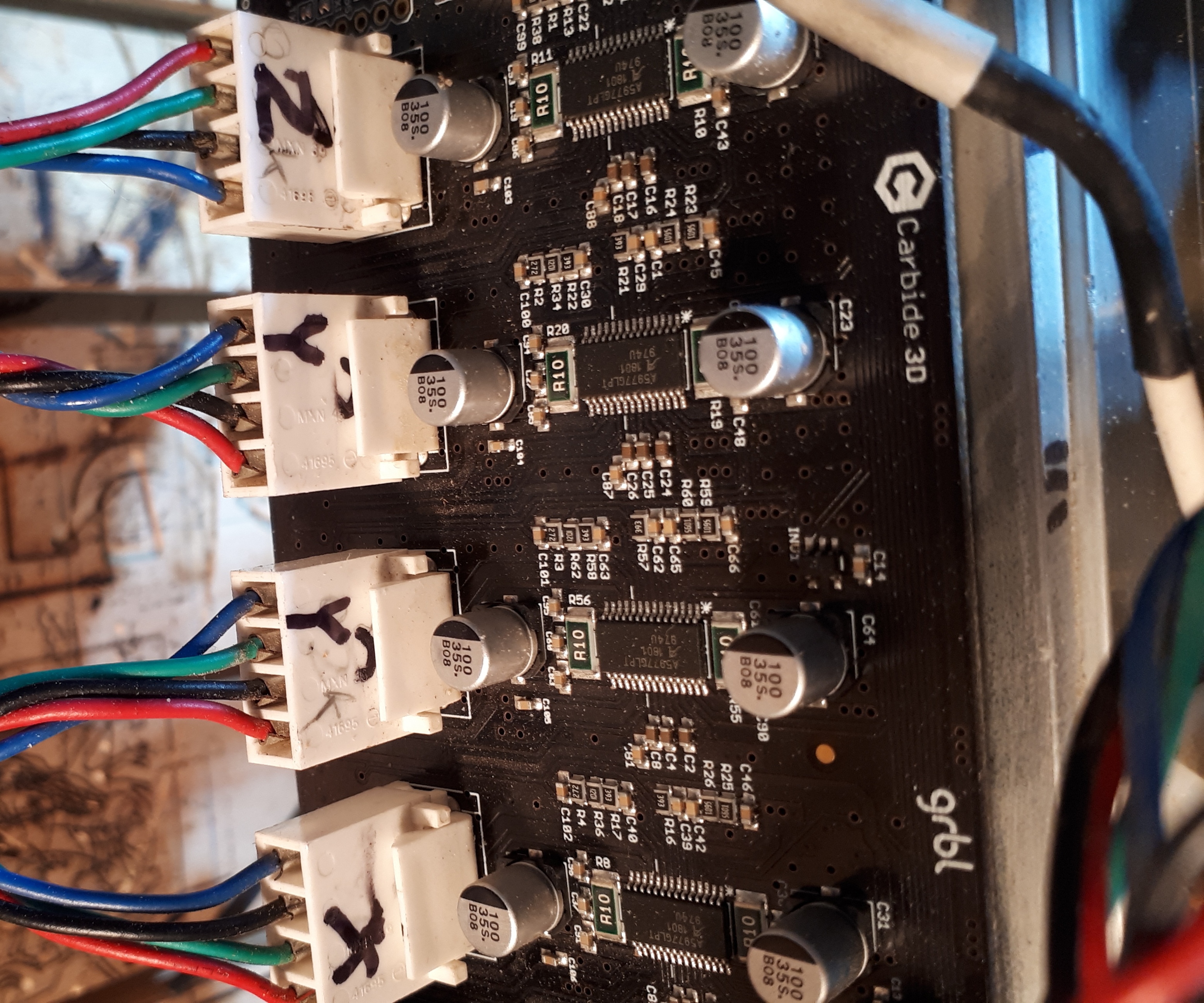
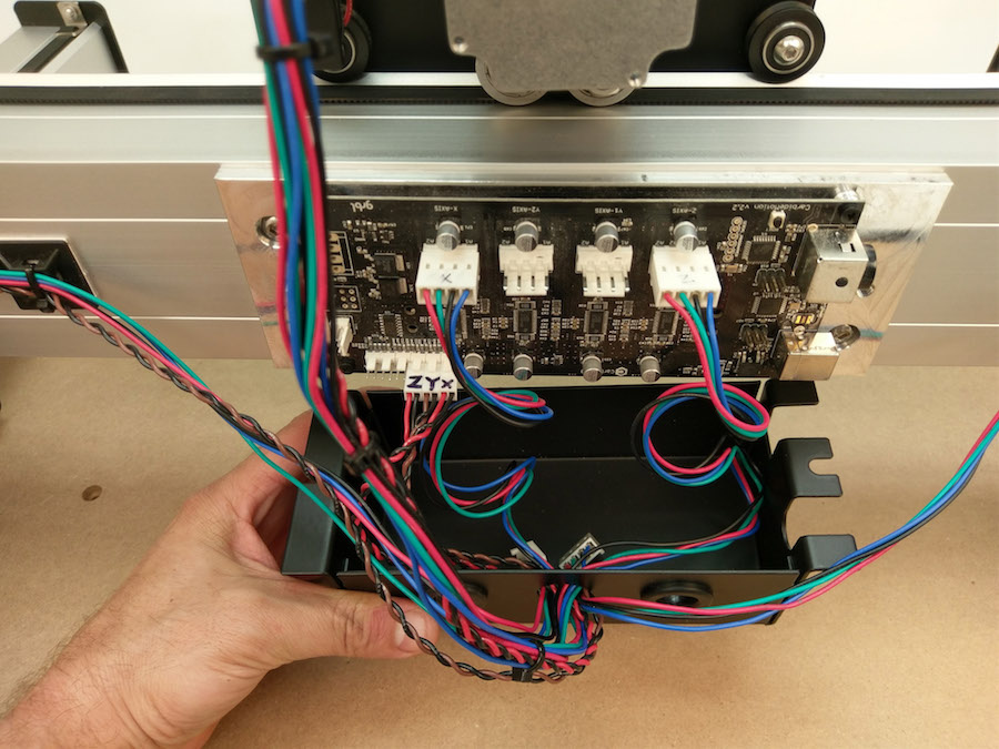
A1/B1/A2/B2 are just the names of the pair of wires going to the coils of the stepper motor, you don’t need to care about that. Mine matches the red=>green=>black=>blue as seen on that old pic from the online assembly instructions,
BUT honestly it’s hard to tell if the wire color is a good indicator, things have changed over the years so different machines may have different wire colors and I don’t want to provide misleading information, especially since while the colors are all over the place in yours, the Z and Y still work fine apparently.
Was the machine moving correctly on X, Y and Z before the laser upgrade thing ?
Maybe there is a loose connection or damaged wire somewhere in the wiring between the controller and the X axis stepper motor ?
To sort this out I’d rather you contacted support@carbide3d.com, they should be able to diagnose this with you more efficiently.
One test you can do while you wait for their answer though, is swap Z and X, and see if the X stepper still does the weird noise (then power off before it moves too far, because the machine will try to home X axis thinking it is Z…).
If it does still make the ugly noise, you will know that something is wrong in either the stepper (unlikely) or its wiring. If it runs smoothly (but now maybe the Z motors does the ugly noise), this would tend to indicate that there is something wrong with the X channel on the controller
Good morning Julian.
Thanks for your fast response.
Yes all axes where fine before. I will try what you suggested and if nothing happen I will contact carbide support.
Thanks again for your time and have a good day.
This topic was automatically closed 30 days after the last reply. New replies are no longer allowed.