I just downloaded the latest versions of Carbide Create and Carbide Motion, then ran a program I have run many, many times before and it cuts .25 inches low on the wood. I have re-checked everything multiple times, I have probed and re-probed, I have even re-done the design in the new version. Nothing seems to fix the problem. In the simulation it looks correct and the dimensions are correct, but the cut comes out low. I have never had this problem in years of running this machine. Any ideas???
Thanks for your time.
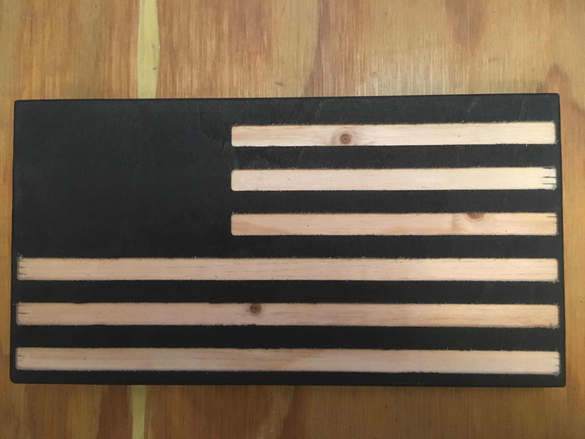
By “too low” I mean in the Y axis, not the Z. My bad. My design ends up being .25 inches closer to the fence than it should while X and Z axis come out fine.
Hi @MadPedalBoards,
Can you upload the .nc file you are using for a check ?
What were the original dimensions of the stock, and what method did you use to set zeroes ?
1 Like
5 x 9.5 American Flag Front.c2d.nc (29.3 KB)
Stock is 5" x 9.5" and I set Zero for all three axis with the probe on the corner of the stock.
Thanks for your help.
Peace
Visualizing the gcode, I would say it cut as expected:
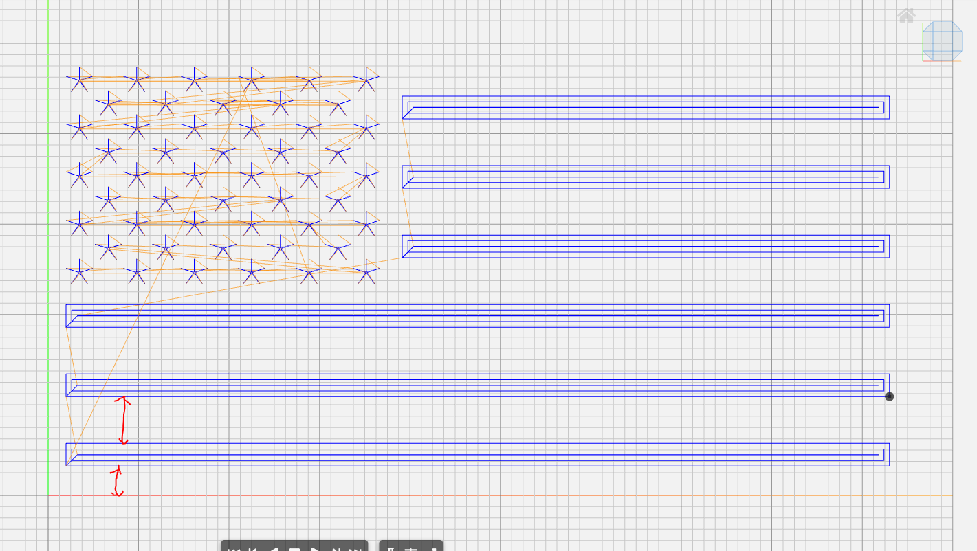
the width of the bottom black stripe seems to be ~half of the other ones in the gcode (visually) and ~1.5x the width of the margin on the left side, so the picture and gcode seem consistent.
So the problem is probably in the design file itself, if this is not what you intended to do.
Can you upload the c2d file for a check ?
What endmill did you use for the cut ? (a possible cause could also be to have used an endmill that does not match what was declared in CC)
1 Like
5 x 9.5 American Flag Front.c2d (292.1 KB)
I cut with a 1/8 flat endmill that has 1/4 diameter shank. Yeah, that pic looks like the cut, but that does not look like the Carbide Create file. Hum. I have run this job many times in a variety of sizes and never had this problem. But whatever the problem is, and it may be ME, I just need to understand what is going on so I can fix it. Let me know what you see.
Thanks for your diligence.
I will be restarting my computer later and running some test cuts.
Peace
I opened your c2d file and just re-saved the gcode, and got gcode that looks like this:

So the gcode file you saved does not match its own source c2d. Can you restart CC and re-save it on your side to see if the issue is gone ? (which we would then put down to a glitch, either of the computer/software or of the person sitting in front of it  )
)
I have a made habit of visualizing gcode files before running a job, for exactly that reason. You never know. I use ncviewer.com but there are many (free) options out there.
2 Likes
That sounds like good news, BUT. I restarted the computer and then probed twice and got the same wrong result. The probe procedure leaves the end mill off center so it appears. Here are some pics. I have not run any cutting test yet. Maybe it has always been “off” and my problem was a glitch, but just wanted to let you see this.
Thanks

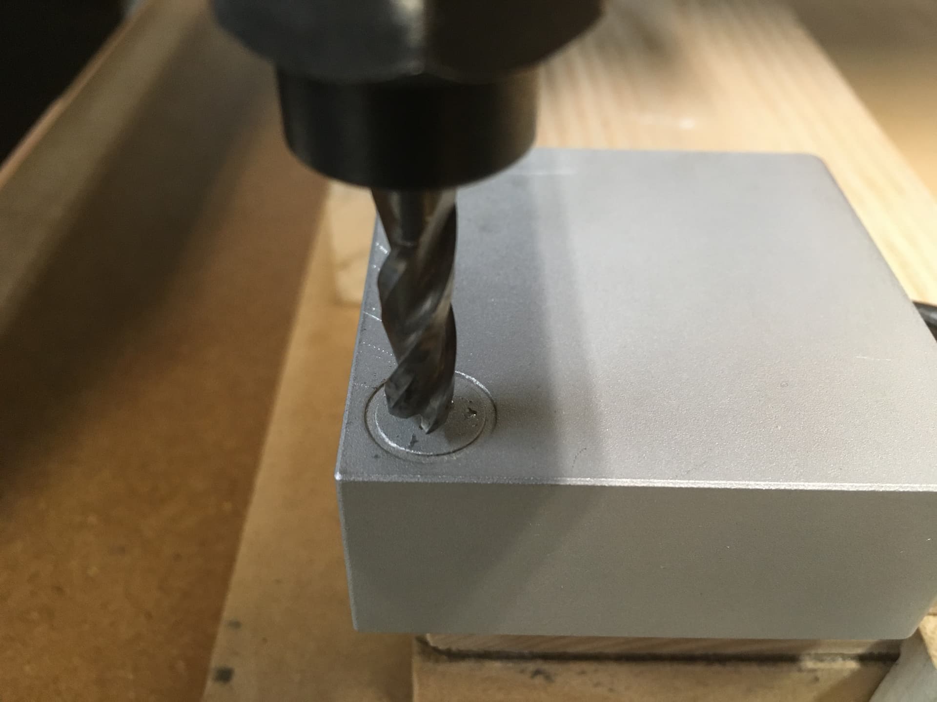
One catch with using a probe with an actual endmill, is that the side probing that the machine does to detect X0 and Y0, is prone to give a slightly different value depending on how the endmill is oriented: if it’s rotated such that the very tip of one of its flutes touches the probe first, you get a correct probing. If on the other hand it’s rotated just so that the probe side faces the space “in between two flutes”, the tool will only contact the probe slightly later, and throw off the measurement.
One trick to not have to worry about this is to zero XYZ using a 1/4" dowel pin (while selecting a 1/4" endmill in CM’s window), and once this is done, swap the dowel for the actual tool you want to use, and probe Z only. In the end you will get perfect X0/Y0 from the dowel probe (no risk of touching in between flutes…), and correct Z0 since you reprobed for that with the actual tool that is going to be used for the job. If you have a BitSetter, you can also leverage that and not even have to reprobe for Z.
All of that said, it’s surprising that you would get the same error on Y twice, and no error on X. But who knows. If this is not it, my last guess would be the probe slipping, but that’s unlikely to happen twice in exactly the same way. And then I’ll be out of ideas
2 Likes
Hey Julien…I could see how that would throw off the “Z”, but why would the flute contact throw off “Y” or “X”? That contacts from the side of the bit, right? (I only have the v1 of bitzero, so I don’t know if v2 uses a different mechanism)
case 1 in red: while probing for Y or Y, the tool approaches the probe face with one of its flutes aligned with the normal to the probe face. The contact point (green) will match the tool cutting diameter)
case 2 in orange: the tool approaches the probe “in between” two successive flute. The probe may contact that outer edge of the flute, resulting in an incorrect X (or Y) probing measurement.

Of course, this is a 2D view of only the very tip of an endmill, and with most endmills the helical nature of the flutes compensates for this: if the endmill is low enough below the probe surface, it should always be one point of the flute cutting edge that contacts first, and the measurement should be correct.
I’m not saying this is what happens here, and I would be very surprised as I mentioned if this happened twice and produced the exact same error, but I thought I would mention it as this is a possible cause for some endmill geometries and measurement conditions.
2 Likes
First, thanks for all your help. Looks like we will have to call this one a glitch. After restarting the computer and re-creating the design in a different size and cutting, I get a great result like I used to. I can only assume that updating the program mid work flow was a bad idea.
So, anyone reading this, when you update either or both of your programs make sure you restart the computer(s) before you use them. I should know better.
Peace
Madison-MadPedalBoards
1 Like
This topic was automatically closed after 30 days. New replies are no longer allowed.