Thats a cracking job, you are much better in f360 than I am!
Pointers:
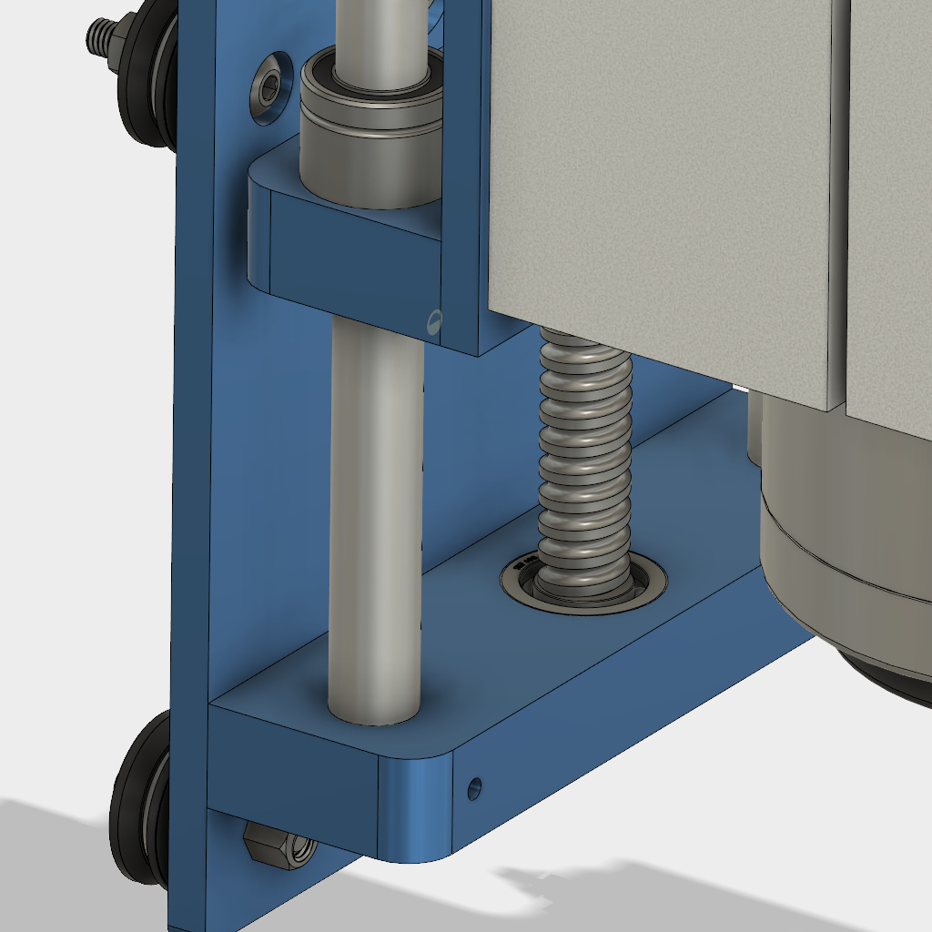
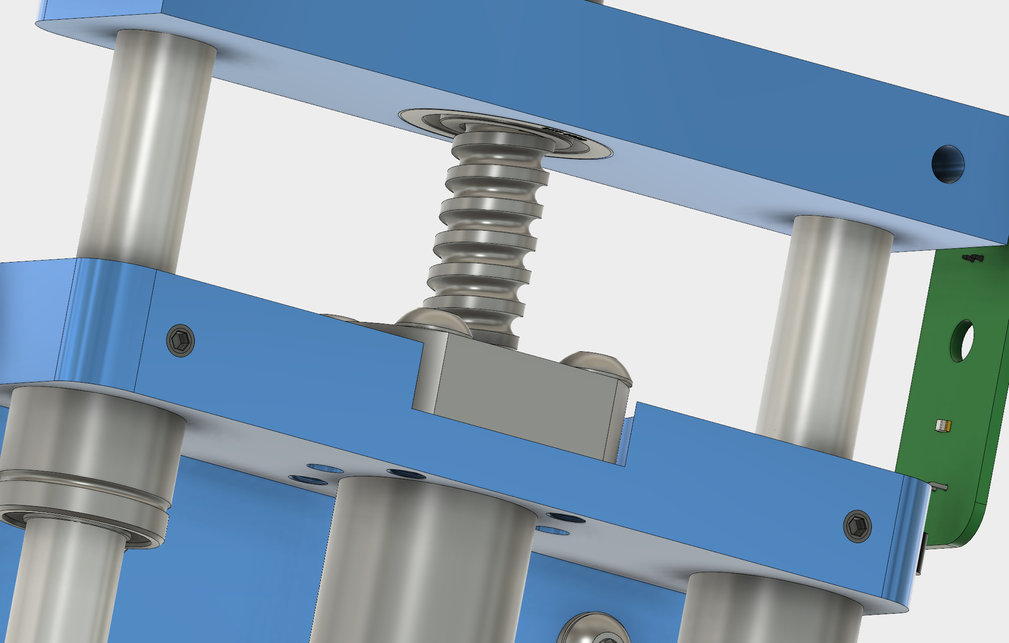
The top of the Z is the wrong way around, rotate it 180 so the counter-sunk hole is pointing down (it’s to allow for nuts/screws to sit in)
The ‘blocked by bottom mount’ holes on both sides and directly above are for if you upgrade the X with the same method - knock up 2 more of the brackets and you will have a linear X upgrade.
The ‘spare/future’ are countersunk on the other side (I was lazy and rather than creating the counter sunk hole I just did it on the face)
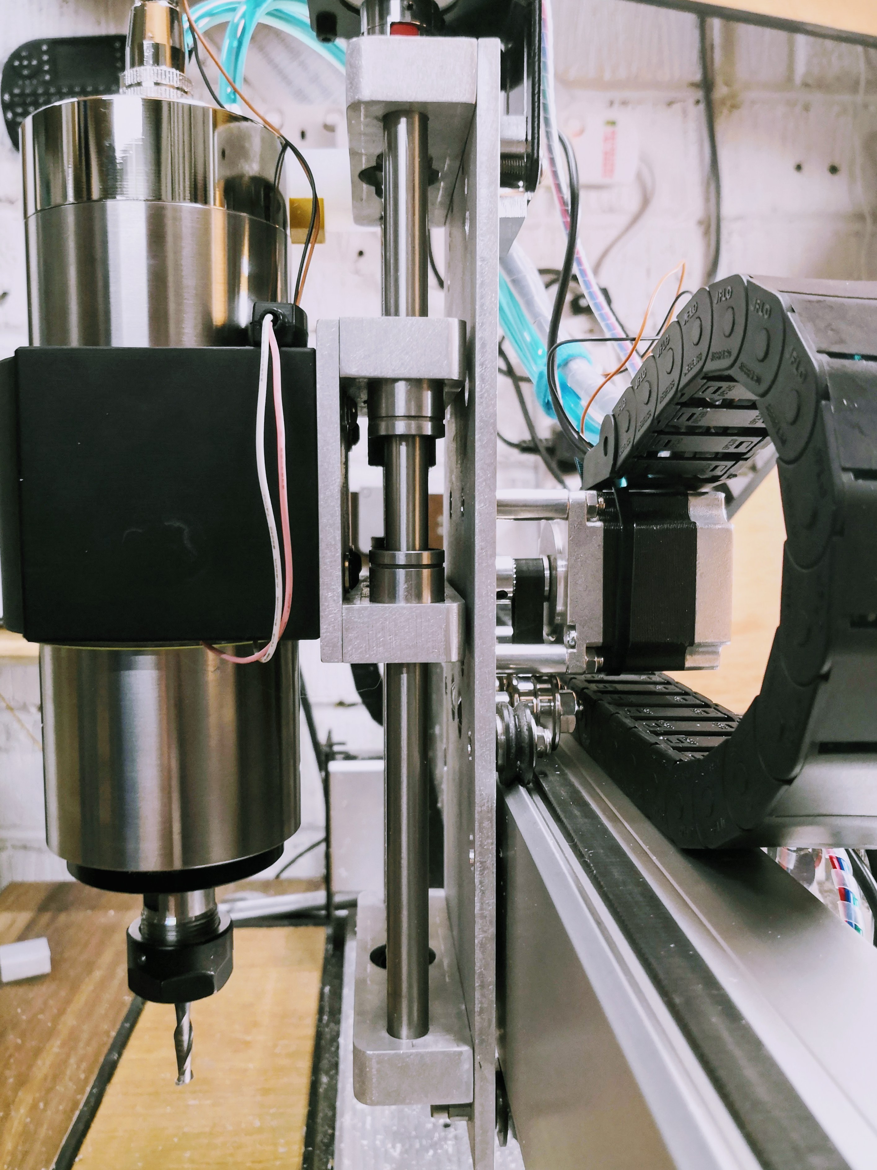
That looks really good Luke! I like how you’ve ditched the original X axis plate, looks a lot flatter (less lever arm) than I had imagined(a good thing for sure!). Nice work!
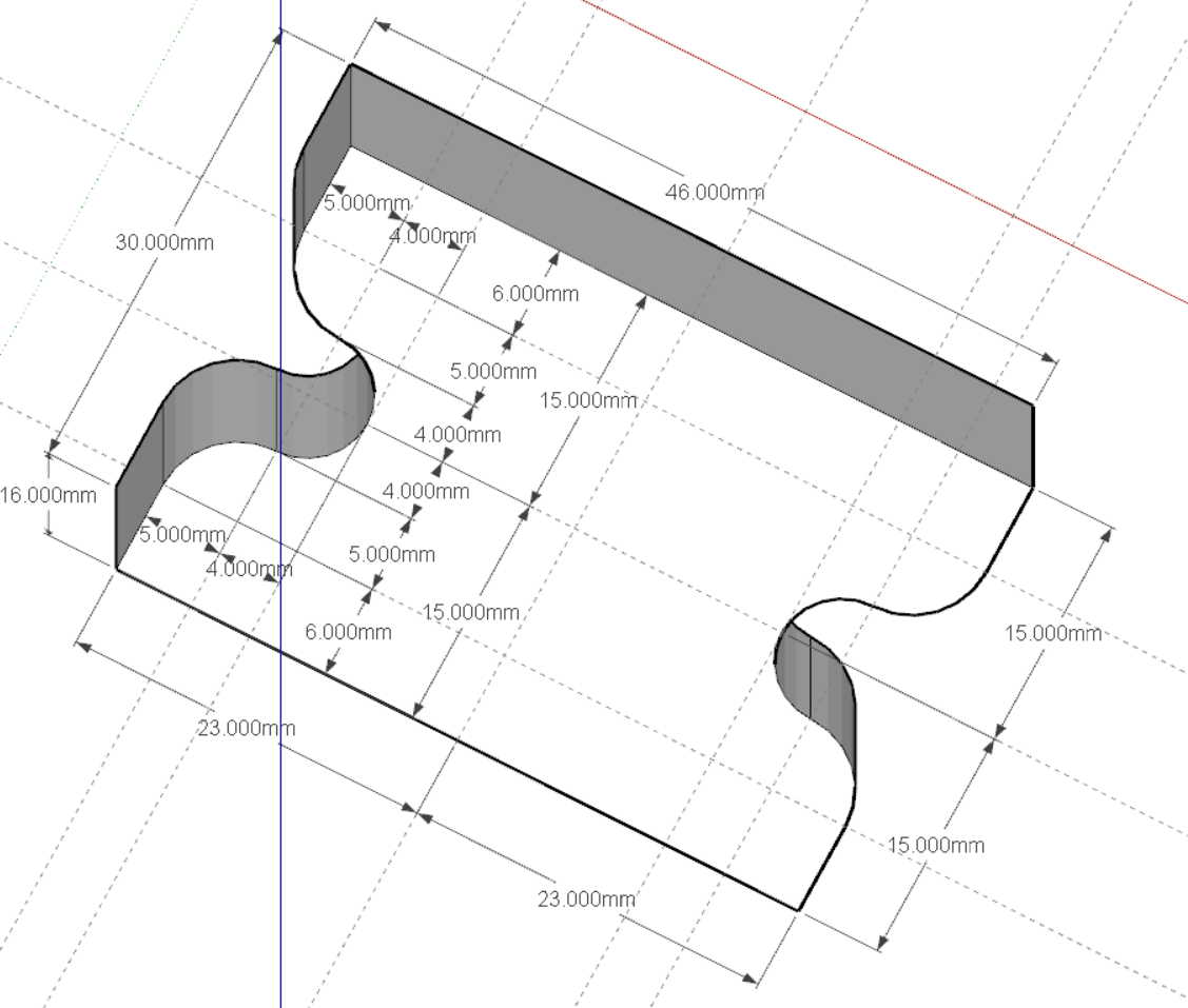
Just looking at the sketchup drawing of the spacer downloaded from fusion. It is exactly precise, I set the sketchup precision to 8 decimal point and there is no roundover (ex: 6.00000000mm) . Thanks Luke for some terrific working models. See picture of it after dimensioning it in sketchup,
I’ve had time on my hands as my ball screw didn’t ship before the Chinese New Year holidays so I’ve been playing with your design. I’ve made some changes to match my requirements but I’d appreciate your feedback in case you’d already considered or tried any of these and identified issues.
I’m making most of my pieces from 15mm alu rather than the 16mm you used as I can get 15mm handier.
Bottom Mount Bearing - I’ve mounted the bearing higher in the bottom mount to get more stock under it for enhanced strength. I’m guessing you mounted yours deeper to allow for the length of the ball screw you ordered but just wanted to check if there was another reason?
As per the bottom mount bearing I’ve mounted the ball screw flange higher and the top mount bearing lower to give more strength. I’m getting my ball screw cut to allow for this. I appreciate I’ll lose some Z height as the carriage can’t rise flush to the mount, I’m sacrificing 5mm for this additional strength.
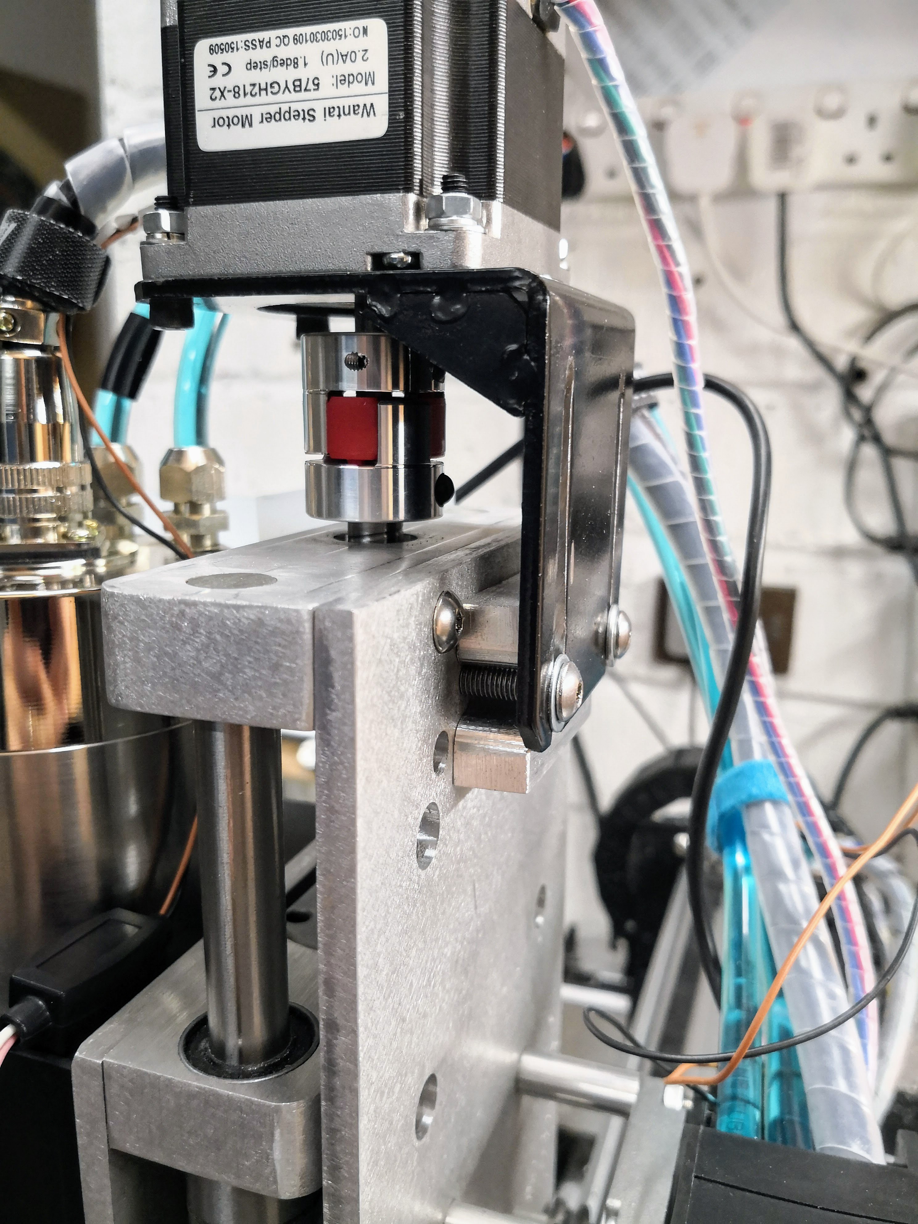
Finally I’ve changed the Z-Axis motor mount to belt linked as I can’t get the motor mount handy and I just wanted to try this. Have you any thoughts on this?
Any feedback most welcome. Thanks again for this inspiring design
Tommy
BTW, you mentioned that I’m better with Fusion than you
Assemblies are just a case of learning to use the Joint command and having time on your hands. If you’re not already familiar with it I’m happy to post a short video but it’s really simple.
Forgot to mention, I’ve a full assembly done with your mount, an 80mm spindle and the rest of the Shapeoko 3 base. I’m happy to share if anyone wants it.
I’ve made extensive use of sub-assemblies so can’t share a .F3D file but if anyone’s interested I’ll see what the options are.
Also, I don’t intend to anodise the parts blue, I do have SOME taste Just coloured them that way to identify the parts needing made.
Nice looking designs! Looks like you may already have it, but I’d slot the bolt holes for the stepper pretty significantly to allow for adjusting effective belt length. Not sure what the stretch factor is on a gt2 belt, but I’d want to have plenty of slop in there to pull stuff tight if needed.
15 mm will be fine but you will need a way to hold the stock down. I used 20mm as I milled a part 16 deep, I’d use the remaining 4mm to keep it held in a low profile vice. Once the main detail was outlined I’d flip it over in the vice then shave off the 4 mm one side - I’m not sure how you would hold these parts down unless in a vice. I guess you could use double sided tape but if they get warm… You could get away with 10mm it would still have done the job.
Bottom mount bearing is fine but if you’ve ordered the same spec ball screw it means you will need to move the top and or bottom mounts holes.
on your top mount you have no recess for screws - no need for it I guess, there is plenty of travel but worth flagging.
love the belt mounted holder, if you figure out the belt requirements let me know and share, I’d like to do this too. One question, how will you mount it to the plate? Holes the motor side I assume? You could be really clever and use one set of mounting holes to mount both top mount and motor mount.
All in great job, I’m well pleased. I have played with the joint command but I haven’t had a proper play, I have no idea where to get things like the ball screw design, or a 2.2kw spindle model like you’ve gone.
Thanks all for the continued good points. I’m still looking at this as well, but I think the first step is that I am going to have to convert over to a different G-code sender like UGS or bCNC, since Carbide Motion doesn’t allow you to change the amount of Z-axis travel. I’m leaning towards trying bCNC first before I go down the rabbit hole of building a z-axis.
In all seriousness, you’re the one that started with a blank sheet of paper. There’s a world of difference between tweaking an existing design and starting from scratch.
I’d never heard of the masking tape/CA glue method until you mentioned it in one of you posts. Will give that a lash first then look at plan B (I’ve ordered a fairly long bar so can clamp either end and use small tabs)
I’ve checked with the people making my ball screw and they’re OK with me submitting revised drawings so I’ll modify the screw rather than the mount.
Yeah, I lose 5mm without the recesses but I’ve still 125mm+ from the bottom of an average sized mill bit to the bottom of a 4" drill vise which is about 130mm more than I have at the moment
Thanks. Will look at how to share the drawings tomorrow when I’m at my main PC. See below for mounting, as you suggest I’m planing to do it with one set of mounting holes.
Had to draw up the screw myself but found a flange online. Google “whatever you’re after” plus 3D model and you’ll usually be spoiled for choice. Many of the better models are SolidWorks but Fusion 360 is getting pretty good at importing SolidWorks files.
The tape method works well for larger sheet work with aluminium, I think tabs is a better option for the 15mm bar bits, you will need a few tabs mind - and take it steady - slotting 15mm on a shapeoko can be a little hairy. I’d almost be tempted to say cut the all 4 sides as slots then leave something like 2mm depth of the short sides and trim those off by hand after rather than using tabs.
Whilst you will have around 130mm more than the stock mount you loose whatever size the carriage is.


 Just coloured them that way to identify the parts needing made.
