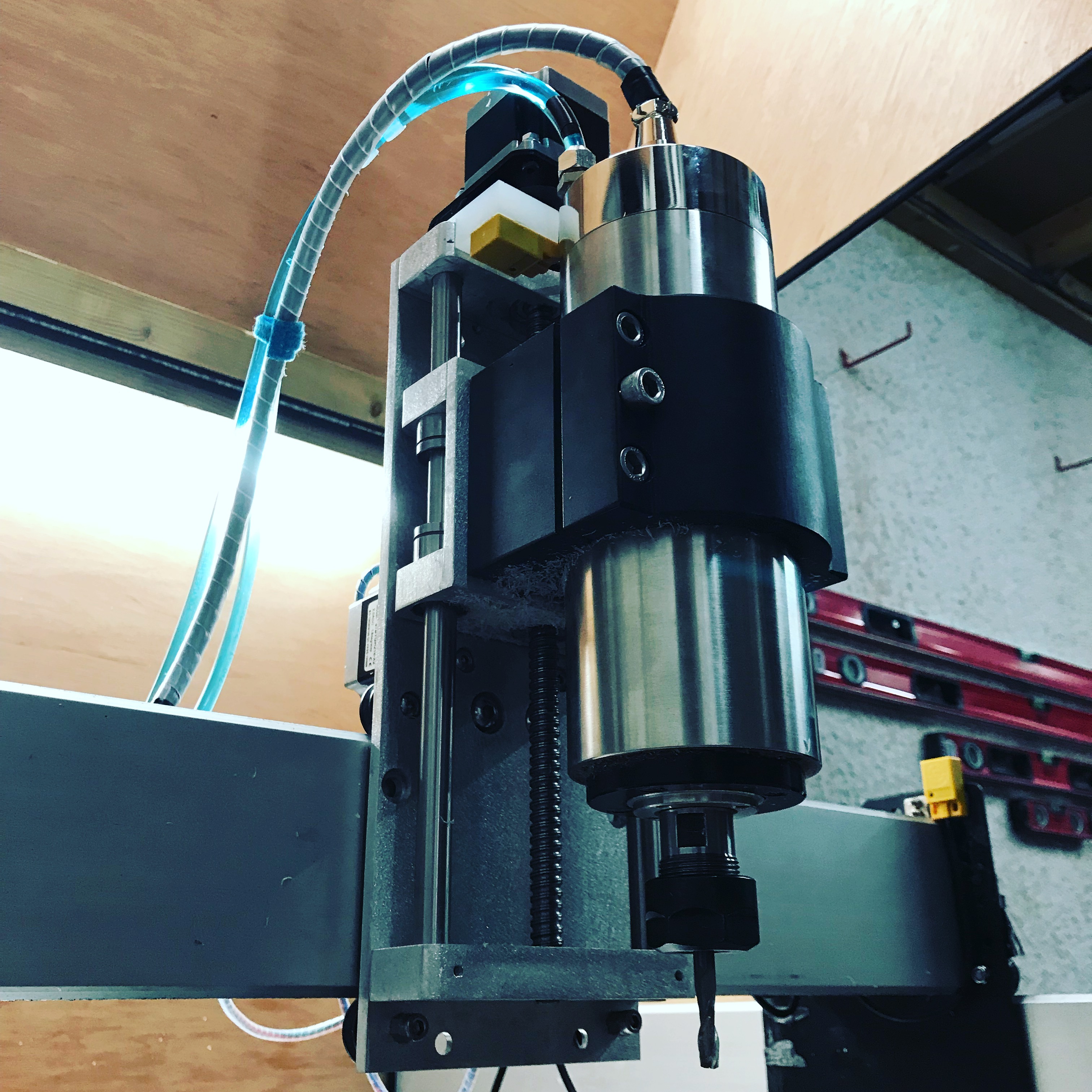
Following on from my Z axis linear guide upgrade I’ve been asked by a few people for drawings and spec, so here it is.
For reasons why and more detail on the results please take a look at my youtube.
The approx cost of this is £50 or $75 + time.
First off you will need a ball screw and nut - I had mine machined in china this is the one I bought. This company will be able to mill a custom size which is very important if you want to use the below design. If you do not adhere to this spec the below will not fit.
When purchased ensure you ask for 300mm – have one end milled at 8mm x 10mm the other at 10mm x 25mm. I repeat t’s important it’s milled to this spec of the base plate will not fit.
Other items to buy include:
• 20mm x 40mm aluminium bar
• 6mm aluminium sheet (around 60 x 13cm)
• A selection of bolts M5/M6
• 1 x 8mm x 22mm bearing
• 1 x 10mm x 26mm bearing
• 4 x M4 grub screws
• 12mm stainless rod (approx. 70cm)
• A 6.35mm / 10mm coupler – Don’t buy the spring sprung version
• A 23 motor bracket – 57BU
• 4 x 12mm sliders – LM12UU
Any other hardware can come off your existing Z.
You will also need a set of hand taps, machine vice masking tape and super glue. You will also need a 1/4and 1/8 mill bit. You will need some kind of probe - I used the Carbide motion probe with great results.
Now for some design files. My tool paths are no not useful for most, as I use metric buts but the files them selves are good.
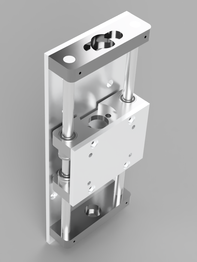
Lets start with the plates, I milled these by using the super glue and tape method.
The router plate – 6MM aluminium plate – the 4 holes in the centre are for my mount – you might need to drill new holes for a stock mount.
http://a360.co/2BykM0C
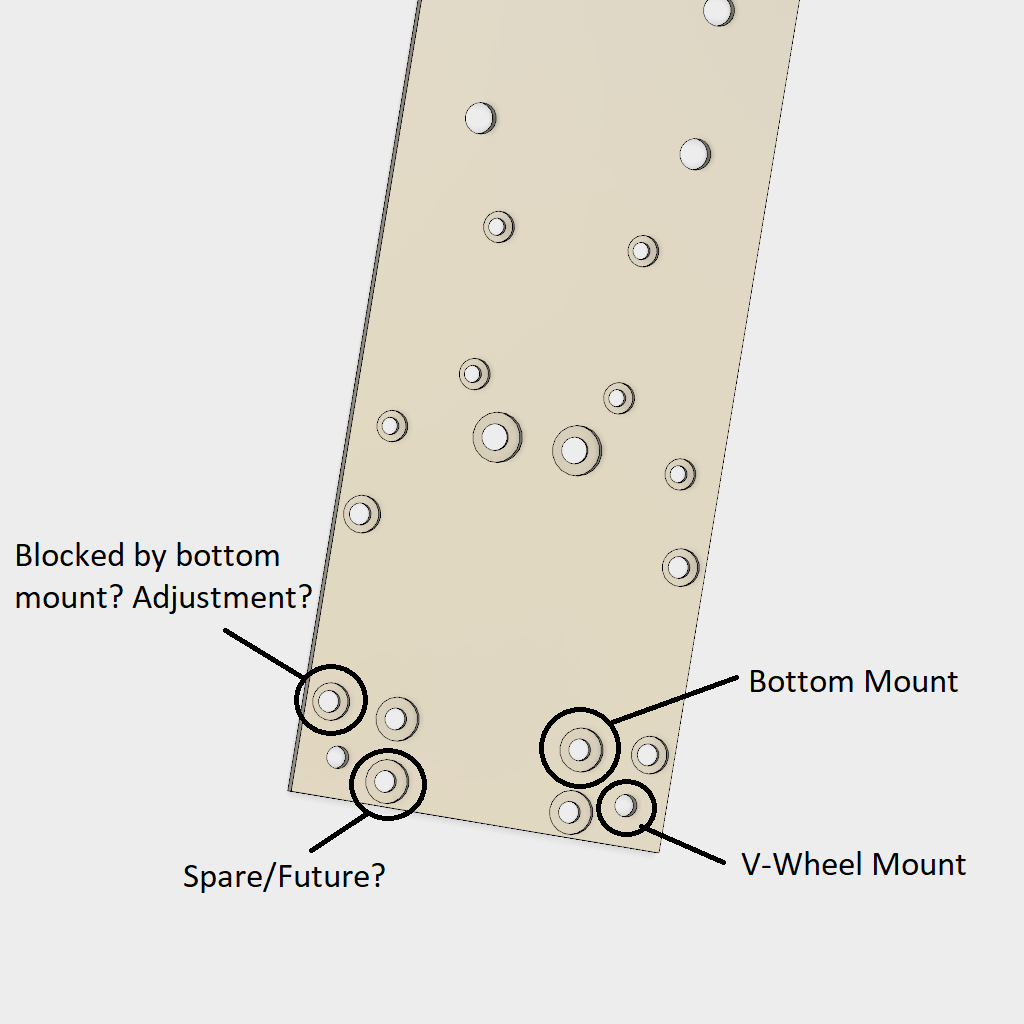
The base plate – 6mm aluminium – this is the most complicated part of the guide. It also requires 2 sided milling.
http://a360.co/2BAuY8x
Now for the mounts – these are made from 20mm aluminium, I did them in a machine vice. I milled the main detail to a depth of 16mm. I then flipped them and took a further 4mm off each face. I then use peck drilling to do the holes on the sides - the side holes were done using the last of the files called ‘Holes’
The top mount
http://a360.co/2EfKsSt
The bottom mount
http://a360.co/2AyTFFJ
The carriage top – this will take a 24 or 22mm nut – I want to tidy up the design – The nut holder could be more accurate.
http://a360.co/2DHAuIo
The carriage bottom (if you want you can mill 2 of the top carriage – either will work fine)
http://a360.co/2DK4E21
Holes – these are for the side mounting holes.
http://a360.co/2DIVLFQ
Spacer – to mount the motor correctly
http://a360.co/2DIF11o
Know yourselves out!
At this stage I don’t have a step by step guide but I’m here to answer any questions.
 I did tidy them up this morning.
 When it comes to aluminium I think it would be cheaper to set up my own mining, smelting and rolling company in the back garden compared to some of the shipping quotes I get