ok when i bring the x beam forward and initialize the maching the z moves down a littlt then up and x and y move back and z just sit in the center making noise and vibrating and if i put metal in front of the limit switch it stops
It’s really hard to tell what the Z does here.

It should do the opposite. It must for the Y to move.
Can you see the X motor shaft/pulley when this happens? Seems like a pulley with no set screws or a wiring issue on the X.
This one;
Looks to me like the X stepper has a wiring fault.
1 Like
im really stupid how do i put a video on here i can do a better one and if it is a wiring fault how do i fix it i followed the lettering on every wire
1 Like
Take a picture of the connectors at the board first. Post here.
1 Like
ok but i dont see where to post the pic
No evidence of that so far ![]()
Once posted on youtube just copy the https : // YouTube? blah link, you can right click on the video and select “copy video URL” and paste it onto a line in the compose dialog box here.
It may get a bit more complicated from here, what I would do is swap the wires between one of the Y motors and the X motor and see which didn’t work.
It might be best to call support and ask them to walk you through how they want to debug it if you’re not confident messing with the machine.
Neil or others may well have better ideas though.
There’s an upload button, the one with the upward arrow which lets you upload attachments like images when you’re composing your post.
1 Like
ok i switched wires every thing worked fine except the z
1 Like
So, you switched over the X and Z motor wires?
Were you able to take a picture of the wiring as connected to the control board as Neil suggested?
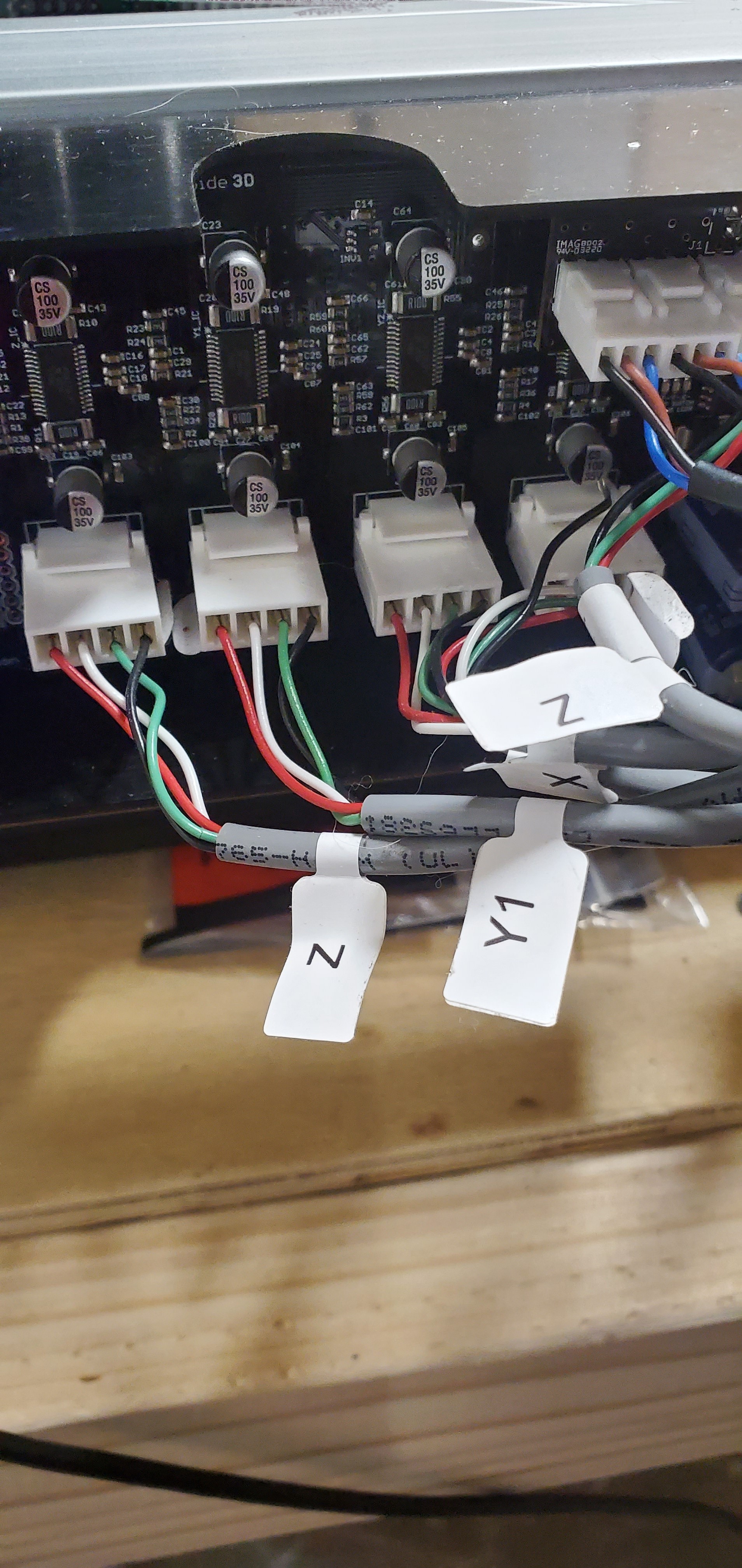
Looks like Neil may be right (again)…
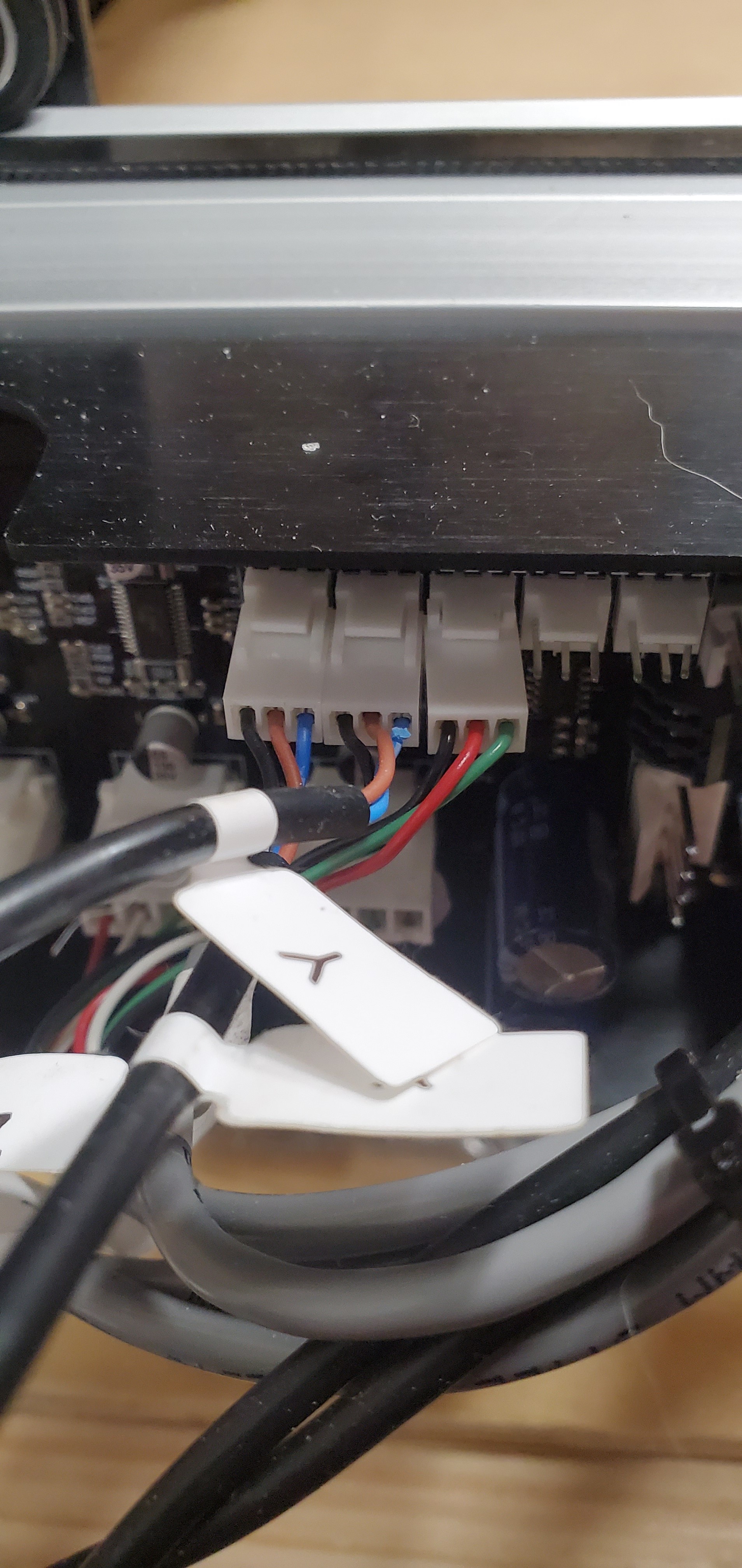
It looks to me like the black wire from the X stepper connector is out of the white housing and dangling on the board instead.
Can you pull that connector off the board and see if all four wires / pins are in it pls?
yes black wire is out how do i fix
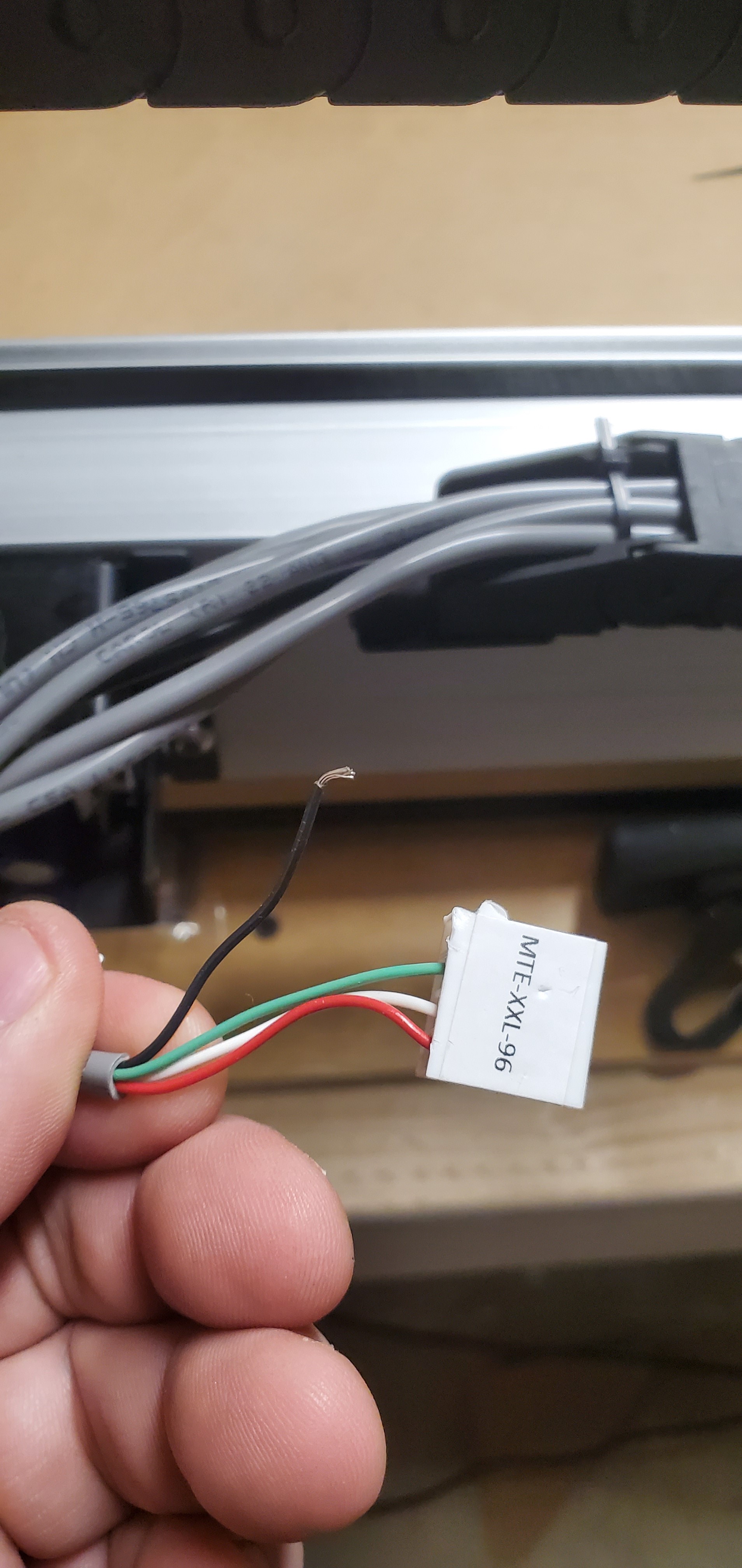
With the connector removed from the board it should be possible to push the black pin back into the connector housing.
You’ll need to have the crimped end of the wire the right way up. If you look closely at the bit that is crimped to the wire, at the end of the insulation you’ll see that there’s a pinch where the two sides come together. You want to make sure this is facing the same direction as all the others.
It should clip into the connector.
the wire came out of the crimped connector does not look like it was crimped to begin with
1 Like
is there a way to pull the connector out and re crimp
1 Like
Not really, you generally use a new crimp connector for that, and you need the crimp tool.
You could try removing the crimp but it’s not easy, you have to find the release clip. I’d solder the wire on to the crimp but I’m used to doing wiring.
I’d suggest calling support and asking them to ship you a replacement cable now.
1 Like
is that something that would be under warranty seeing as to how it is only a day old
Carbide customer support has been pretty good in my experience, they go a long way to get customers up and running. I’m sure they’ll get you sorted.
1 Like