When I import an .stl model in CCP, is there a way to turn on the location snap? I am trying to locate 2 models along an edge and I cannot seem to precisely locate the models. This is important to me in this case as I will be doing a 2 sided carve on these models. Am I just missing something or is there another way I have to handle this? Thanks in advance!
3D components when imported are centered on the geometry which is selected when the import is made.
Right, so how can you locate 2 separate models in relation to each other if they both load on center and you cannot drag them along an axis to relocate? I know I can get them close but is there a way to do this precisely? Or is this just a limitation of the software?
A picture is worth at least a few more words… ![]()
(Can you include pictures of the 2 models?)
Are they 2 separate models? or the same model just flipped over?
If the models are built with a common edge or corner, they should import within the same space.
The import function looks at the overall size, or bounding box of the faceted body (STL).
So if you reference the same point from top to bottom, it should work.
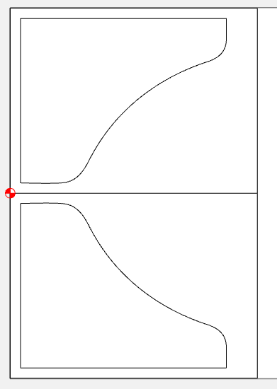
Here is a flipped object where both sides reference the same corner as the zero point…
1 Like

Sorry, I could have included this earlier. A friend of mine is into competitive axe throwing and was interested in a small wooden head hatchet. I modeled the head in F360 and split it to import into CCP. I was hoping to machine but halves together in a single setup and then flip once and finish. I know I can do each half separately but it is more setup time that seems unnecessary to me. When I import each half and drag to reposition I cannot seem to constrain the motion to a single axis which means I don’t know if the 2 halves are actually “lined up” in the layout. This means that when I flip them to do the other side I can’t be certain where the parts are positioned. I hope that makes sense.
Edit: I see how I can mirror and position the vector associated with the model outline but it doesn’t seem to move the 3D info with it.
Ah, OK. Now I get it… kinda…
You don’t have to split them to import them. You can leave it as a whole solid model, then import the top & bottom views. You just have to consider the total thickness as opposed to the half thickness if they’re split.
But either way, as long as the dimensions of the axe head are the same, just make 2 rectangles the same size, and import the model into each rectangle.
If you use the layout I did above, with the zero point in the middle left, then when you flip your stock on the machine, you just zero off the front left corner for one side, and the back left corner for the other side. Or you could do it in two files with the same size rectangle, and use front left for both.
I would recommend modeling it as a solid rectangle without the axe outline shape, and only model the contoured shape of the side of the axe head.
Then on the first side, cut the 3D contour & the outline all the way through.
If this is the bottom image in your picture above, your outline only needs to cut the front & right side.
Then when you flip it, the upper left corner becomes the lower left corner, and on the 2nd side you only cut the 3D contour. Than way you don’t have to line up the split line in the middle.
This topic was automatically closed 30 days after the last reply. New replies are no longer allowed.