I am going to make a Longworth turning chuck for some friends on my SO3. I found a good svg on Woodworkers Journal for a 12" and 16". The problem is the 12" one is fine but the 16" just seems like someone simply increased the size and the slots were made bigger. My question is how to reduce the slots from 3/8" down to 1/4". I tried to create the Longworth chuck from scratch but had problem getting my boolean working. A Longworth chuck is simply a series of 8 circles. However they are only partial circles of a specific size.
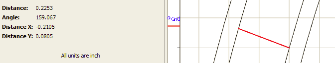
In the above example the slots are about 1/4" wide. The 16" version they are about 3/8" wide which is too wide. They need to be 1/4" (or less) wide to work with the hardware.
So how do I reduce the 16" version or draw one from scratch.
Yes that is how to manually lay out a Longworth Chuck. I want to get it either drawn in CC or get an SVG to create it on my SO3. I have made them manually in the past but want to cut them on my CNC. Any suggestions on laying out the grooves. In the post they draw the partial circles with a compass. If I could just get the partial circles in CC I could just do a contour with no offset or make the grooves 1/4" wide. Since I have a CNC I would like to make several of these and make replacements for the future.
I created two sketches. Layout is the the pencil work to find the points. Path is the arcs to cut.
This is not to scale. Markup an image file or something to tell me the dimensions you want.
Your answer is why I ask my questions here on the forum. I knew about using an offset and yet never thought of it. The answer to your question is yes that would work.
Just to get a working model your solution would work. I still want to figure out how to draw one from scratch. My inquiring mind will likely be the death of me.
The center lines would work because I can just do a contour with a 1/4" bit with no offset.
Thank you for working on this.
My question is how are you making the lines in CC or are you using something else and importing into CC. I am wanting to make this Longworth chuck for a friend but also interested in how to make it from scratch in CC.
I made parametric sketches in Onshape and exported them.
I can change dimensions and scale as needed.
It would make me nuts to layout things in CC. I am too used to real CAD systems.
So mark up something up with the diameters dimensioned and the width of the slot if you want a real contour.
I can send you a link to the Onshape document if you want.
I use the free version on Onshape.
It has everything I want and I don’t care if the Document is public.
Thank you for making the drawing. I will check out the dimensions in the morning. I too am fading. Had a long day of yard work. Spring cleaning and having visitors coming for Easter.
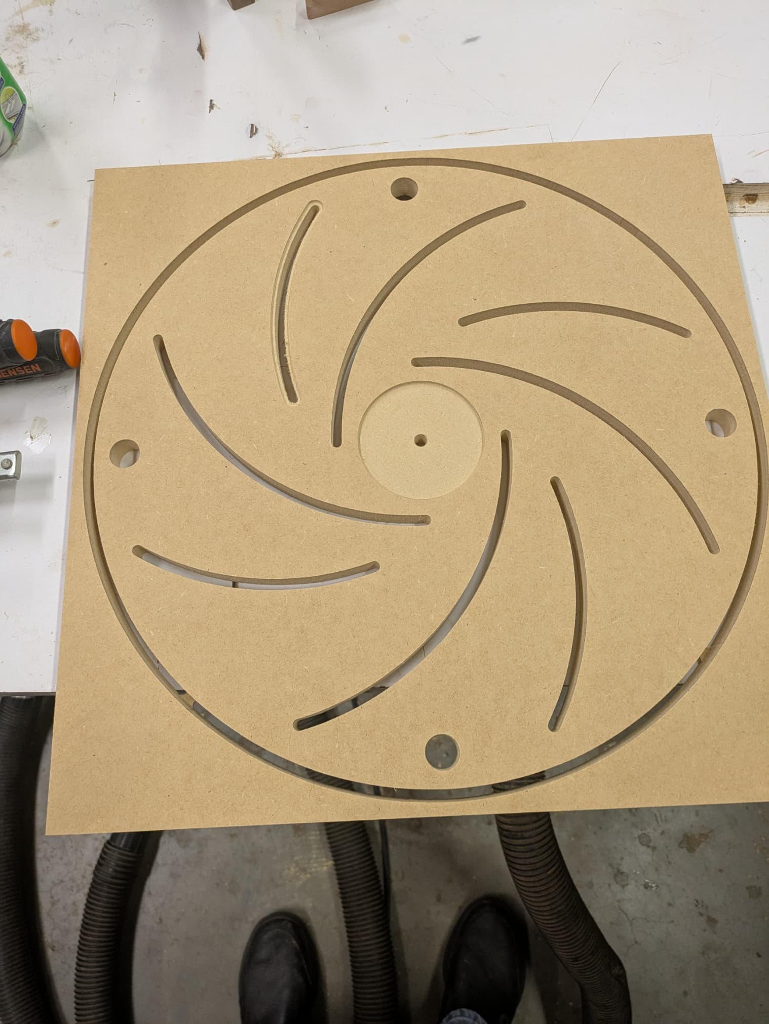
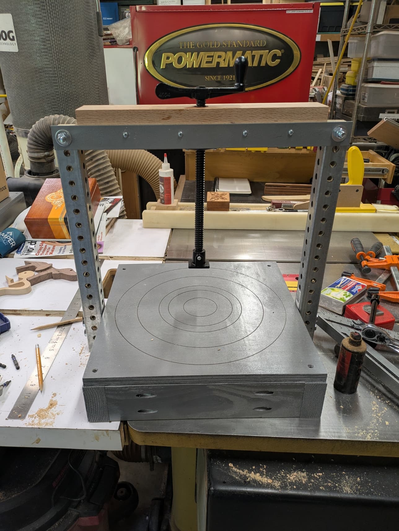
The design @jtclose worked for the 16" Longworth Chuck. I had to keep doing an offset on the curved parts until a .25" bit fit inside. This is the back plate. I will try to cut the front plate later today or tomorrow. After the 16" one is done I need to make a 12" one. These are for some of my fellow Wood Workers of East Texas Club.
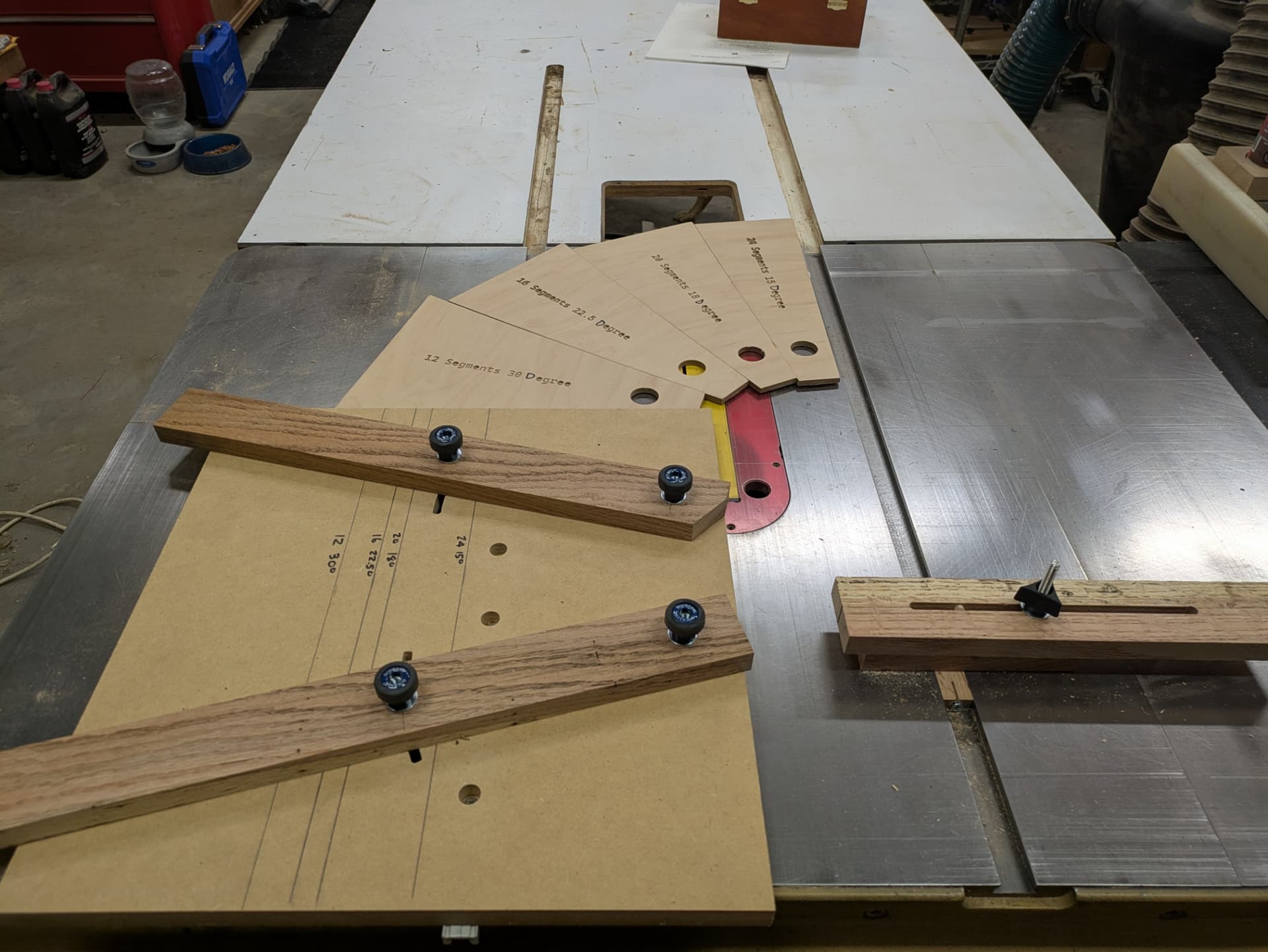
I made two of these to go along with the Longworth chuck. Previously on my SO3 I had made two Wedgie Sleds to cut the segments on a tablesaw. I designed the Wedgies in CC and cut them from 1/4" plywood.
Thank you but I have a 12 inch one already. I was very nice of you to make the 16" one.
I ordered the hardware needed to complete the 16 inch one that I cut out. I have several days of rain predicted so I will be working in the shop. Bought a sheet of .75" MDF Monday and will be whittling that down. Going to make the 12" Longworth Chuck and a new spoilboard for my SO3 XXL. The spoilboard is not really hard to make but it is time consuming. Along with the new spoilboard I need to do routing maintenance to my HDZ by removing it and oiling the bearings. So after removing it and replacing the spoilboard I will need to tram and flatten.