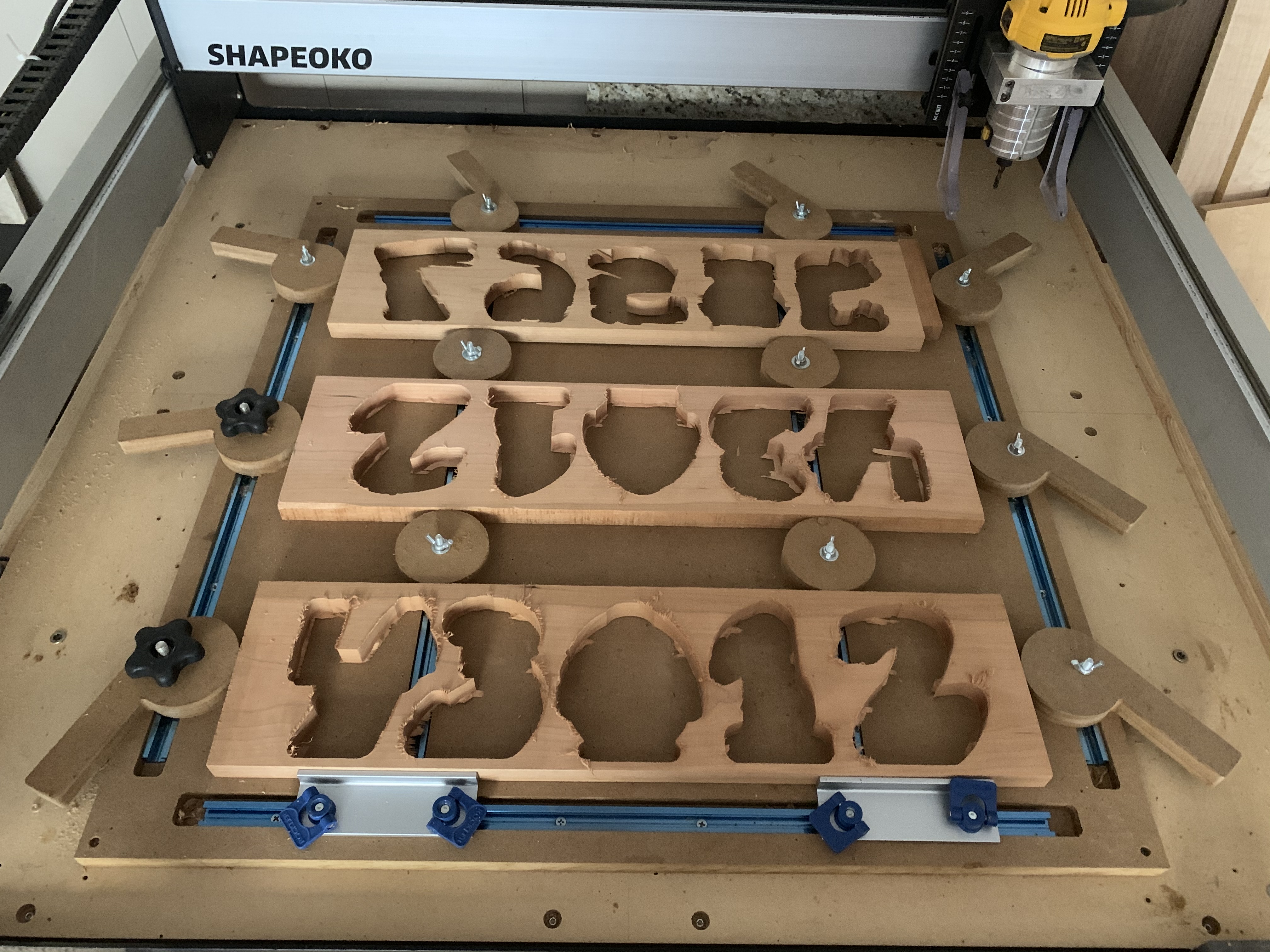
I’m starting to batch out projects for my wooden toy business and I need to increase my output. Part of this is plan includes cutting multiple pieces in one operation. I replaced my old wasteboard with this new design with 6 T-Tracks and wedge clamps to lay out 3, 24in boards at a time. All of the boards are secured from 4 sides but I have nothing holding them down in the Z direction. I’m looking for any input from more experienced manufacturers on this setup. Do you think downward force is required for cutting boards like this? Do you have any suggestions to improve a workholding setup like this? Thank you!!
In the application you have shown, I do not think than downward clamping in the z-direction is necessary. It looks like you’ve used it with success?
Just be conscious of where you are cutting material out and the order of it as well. Your clamping force lines need to have material in-between so you don’t lose that holding force. Seems like you have been conscious of that though.
I have not used this setup yet. I just placed some older pieces that have already been cut to test the clamp force and try to visualize the final result better. That’s a good point about the clamping lines. The danger with this setup is if something goes wrong I could potentially lose much more time than I’m trying to save…
Testing is key, I would maybe think about adding a stop on one of the x-axis directions like you do in the y-axis instead of cams on both sides. It will allow for more consistency in zeroing.
Also, I don’t know if you’ve used those cams yet or not, but you defiantly want to tighten down the wing nuts once you cam them over so they don’t start to un-cam.
Also, If you test that and it doesn’t work out, I’d think about maybe just using top clamps on the sides of each boards with the cams in the y-axis still there. That will have the added benefit of not having to be as conscious of your clamping force lines.
1 Like
I like the idea of just having a straight fence on one end for zero constancy. Plus that means less fidgeting with the clamps before each cut. Thanks for the tips.
2 Likes
I haven’t done it yet, but I am considering adding a “ledge” on the perimeter of a couple of my cam clamps. This would overhang the edge about 1/8" so that lip will clamp down on the board as well as the cam action.
What you have that I don’t have in that application is room. You just need to add some edge clamps.
However, you aren’t really saving much time with cutting those multiple single boards. Now if you were cutting that stuff out of a full-size sheet, you would be saving some time.
If only wood had endless widths
… without adding glue! 
Yeah, you still have four toolpaths and zero points, so it probably will be just as fast to keep swapping them into a single XYZ corner. I do that and rarely have to move much on the zero settings.
If you are using upcut mills you may get in trouble without having z direction clamping. Downcut mills will likely be fine since they are pushing the material into the wasteboard but also have a significant problem with chip buildup in the grooves.
3 Likes
personally I would a strip of double sided tape underneath, and make sure you use downcut endmills… upcut will try to pull the work upwards, which is the weakest direction obviously in your setup. Downcut will push it down… which well if it can push the work through your board you have bigger issues 
1 Like
You can always program it to have one zero for all four boards. It looks like the circles in the center are all precise enough to take account for in a program.
1 Like
I would make two recommendations.
-
Replace those cam clamps with oak cam clamps and make sure the grain runs in the long length. The MDF clamps are mushy and can come loose during cutting.
-
Make an L shaped bracket for the lower left side of your board so when you position a new board in that is the same size your zero will be persistent. Once you set your X Y and Z it stays persistent over power cycles. The key would be that your boards are the same size if possible but if they were bigger and you are cutting the same pieces over and over it wont matter because the lower left corner is consistent and any waste would be on the right side. Without powering off the Shapeoko you can just keep inserting boards and starting the gcode. If you power down at night or for a break just do a quick check by going into rapid position and click the current offset position and the router will go to the origin last set. If your boards are varing in thickness then you must reset Z zero and go into CC and change the setup to reflect the new thickness. Resave the project and resave the gcode files to reflect the new thickness.
6 Likes
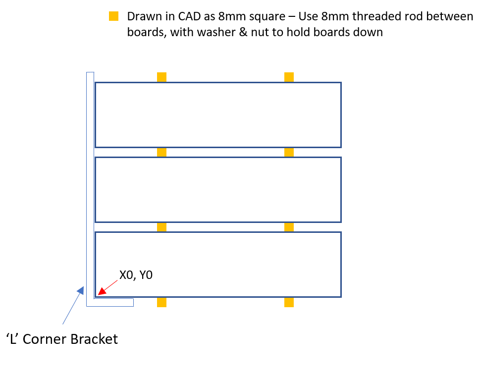
Below is how I would do it if you are making multiples or even just using the same size timber and want to save setup time
- Use an L-shaped corner bracket, ensure it’s square using a dial indicator or even by jogging your machine up and down along the side of the bracket.
- Draw your job in CAD software with the timber drawn to size. Place 8mm (can be whatever size your T-Track bolts are, 8mm is what mine are) squares between each sheet of timber where you will put the hold down bolts. This will align the timber correctly when you lay it out on the machine.
- when you set up the job, put the first piece of timber into the L bracket and place 8mm bolts with washers to hold down the timber in the place that you’ve drawn the 8mm squares in CAD.
- install the rest of the pieces of material with bolts between each board - as you’ve set it up in CAD. Ensure that your bolts are hard up against the timber otherwise the gap between boards will be more than you allowed for.
- Be aware that the washer on the hold down bolts will sit over the board a little, when you design your job make sure you allow for some space for the tool to clear
If you have trouble getting the boards to sit hard against the bolts try putting timber spacers between the boards next to the bolts to space it more evenly
This will allow you to use a single zero for the job, and also mean much more secure workholding. You could even put cam clamps on the right hand side to secure it further (though I don’t think this would be necessary)
See my average powerpoint picture below
6 Likes
Wow this is great. Thank you so much for the detailed response. The main thing I’ve gathered is incorporating these “hold-down” bolts into the assembly. I see now that this would be fairly easy to add to the setup to get some added support in the Z-direction. I Also love the L bracket on the left hand side. I think I’ll create one that can attach into my T-Track on one side.
I definitely have more work to do! Thanks Again.
2 Likes
No worries!
There are a heap of ways to do it, I enjoy seeing how people approach jobs as far as layout and workholding go. I learn so much from it.
5 Likes
So, I guess I’m confused. With this “stack” of three or more boards, your going to create a single toolpath to cut all of them with one setup?
I second the L bracket fence and from the looks of things you should be able fit 4 boards in your work area for even better efficiency.
The problem with a lot of these methods, is that without something backing-up wood, you’ll get some tearout.
Take a look at the pics in this thread:
…and you’ll see my solution. It is my binder-clip hold-down method. It is a piece of wood that is routed to create a lip around the edge. Then the workpiece can be held to the wood using binder clips, and you can even place a piece of disposable something between the workpiece and the jig to prevent tearout.
It really works well, I almost always come back to it when I need a high quality finish or if I want to crank-out several of something quickly.
Correct.
You could set the zero for each board if you wanted to, but if the gap between each board is known and accounted for in the design there is no benefit.
3 Likes
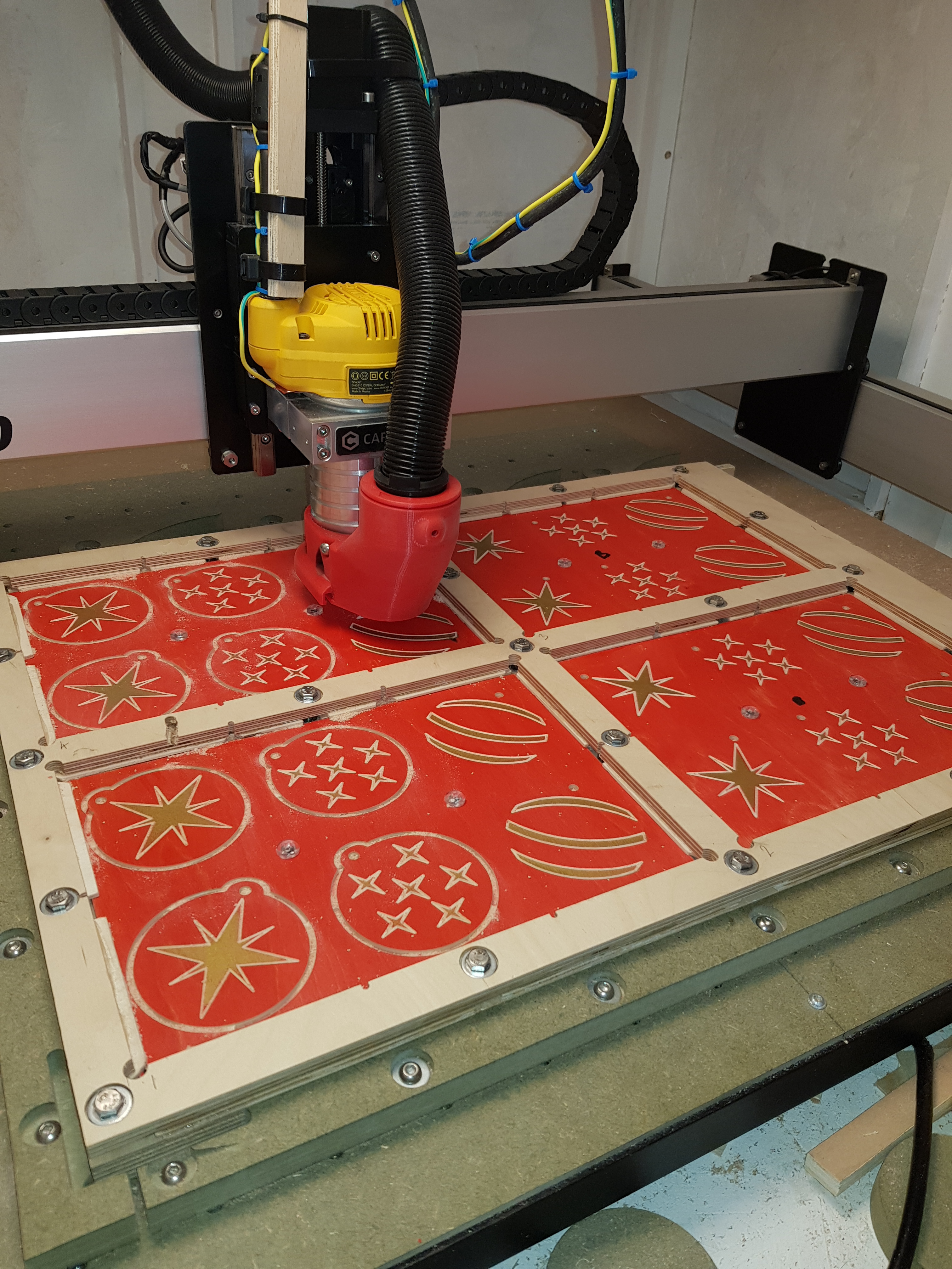
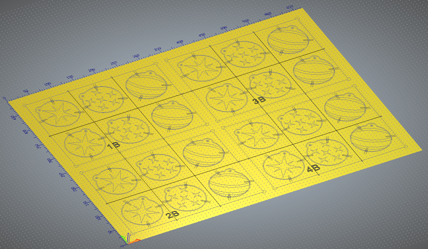
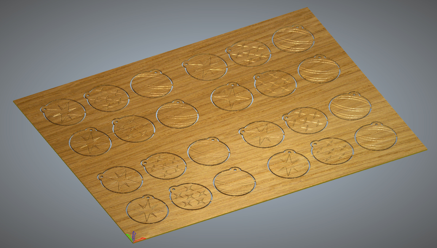
This is exactly how I did my recent Christmas baubles project. All 4 panels cut at the same time. The jig is uniform in all 4 panels and the Z for each is the same. Each panel to be cut sits on its own waste board which is levelled and each panel is uniform in thickness. The CAD incorporate the jig into the design so its easy to only cut the panels and not the jig.
4 Likes