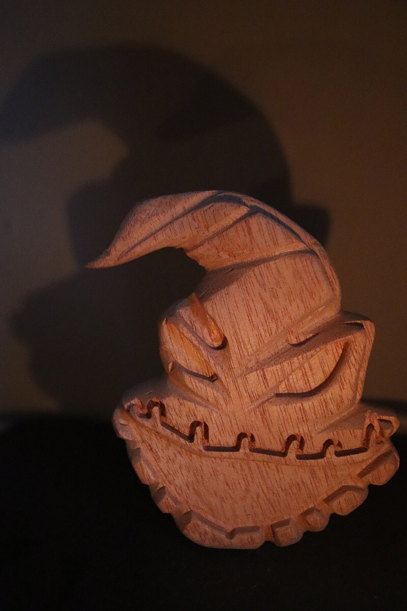
Hi guys I’m scratching my head on how to make the attached carving in to a more rounded shape so I can create a candle holder.
Rather than make lots of mistakes and trial and error I hope it’s ok to ask some of you who may already know the most sensible way to achieve this?
1 Like
Could you not vacuum form a mould for front and for back then cast in 2 parts or even make a silicone mould from the carving?
I’ve just re read the original post. I thought you mean to hold the wax in making candles 
2 Likes
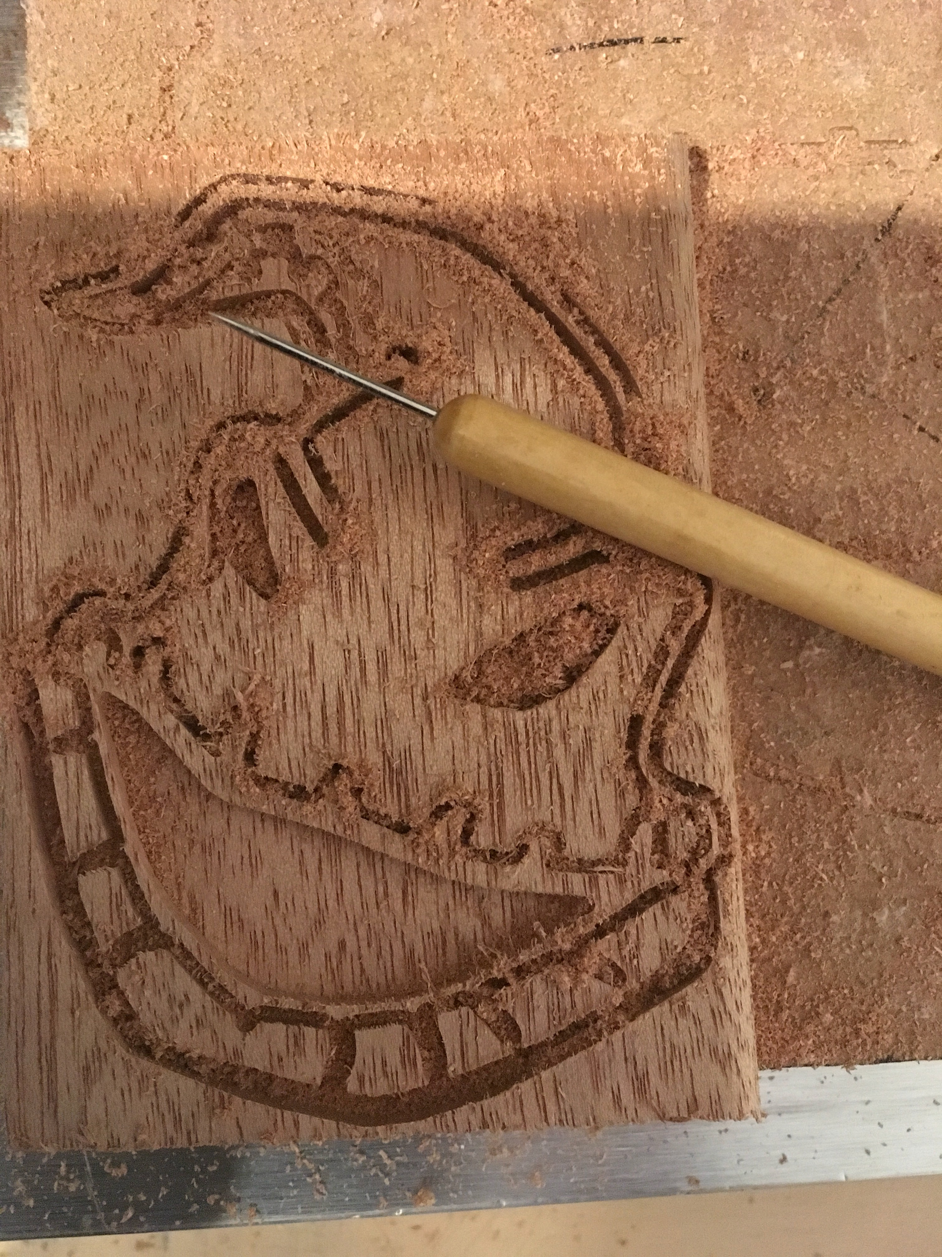
I am presuming that you are referring to the first image, not the second, but he concepts are the same.
If you are using Fusion360, Inventor, Solidworks, or another full-features CAD/CAM tool, you have a number of options, but with simpler tools, options are more limited. Many tools (full features CAD/CAM down to some specifically for 2/2.5D carving only) will have an option called “draft angle”, “wall taper angle” or similar available, often in setting up the tool paths. In Inventor, “Wall taper angle” is in the CAM toolpath setup.
This is originally from the patternmaking world, where a draft angle is left on all vertical surfaces to allow easy removal of the pattern from a sand mold, and has been used in all modern forging, pressure casting, die casting, and molding processes with fixed molds.
If such is not available at the tool path stage, you may have options in generating the model. Most CAD systems will allow you to extrude or draft a profile with taper to allow for the same concept, and some less general tools have options for sloping walls or restricting the angle (say to 87 degrees, rather than 90)
If none of this is available, the easiest option is a tapered mill that are intended for general milling jobs, but do not cut a vertical wall. They have been around since long before CNC, as they were a go-to tool in the manual machining days of pattern and mold making, and are still quite popular. They are available with included angles from 1 degree to 20 degrees or so (larger angles have less selection, as they are drifting into the territory of chamfer mills, vee groove mills, and the like, which tend to have different end designs and cutting edge options), leaving wall angles of 0.5 degrees to 10 degrees. When roughing the part, leave enough material for final pass on the vertical surfaces with a tapered mill, and you will have appropriate draft angle. If the CAM tool isn’t aware of the tool, it can be a bit of work to get a good result, as the tool paths will not be ideal. When purchasing, be sure to read the angle carefully-- it may be specified as ONE SIDE angle-- the angle left on the work-- or as INCLUDED ANGLE-- twice the angle left on the work. Remember: a 45 degree chamfer bit usually looks the same as a 90 degree vee bit (depends on the supplier though…).
If using more capable software, a tapered mill will get a well planned tool path and you can get very good results. (Most CAM software has a way for you to provide a profile that the tool cuts for tools that are not directly supported)
2 Likes
Thanks for the ideas certainly a lot to think about.
This topic was automatically closed 30 days after the last reply. New replies are no longer allowed.