WillAdams
March 6, 2024, 10:30pm
1
The best reference on this is George Bain’s wonderful book:
For more on this artist see:
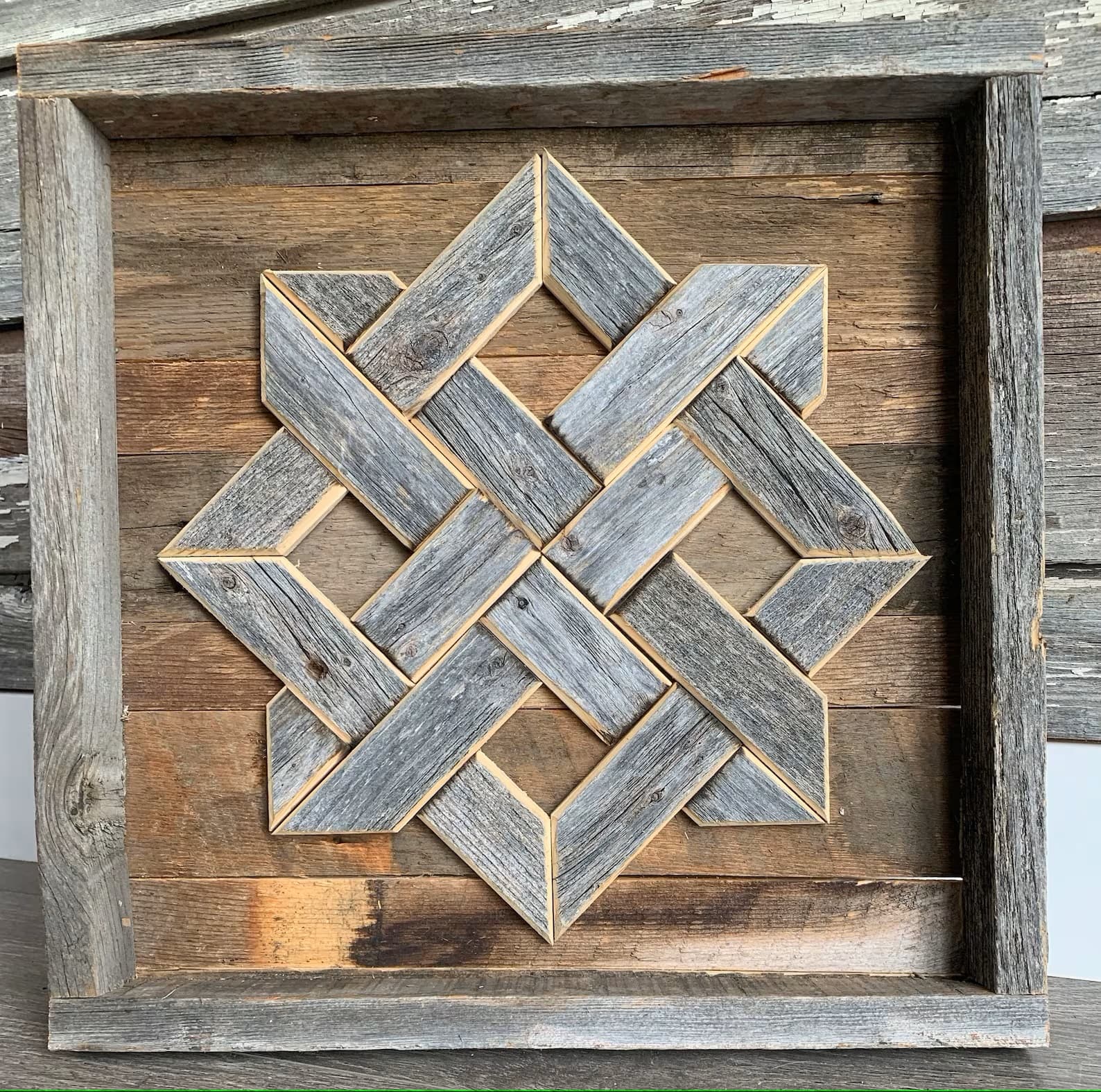
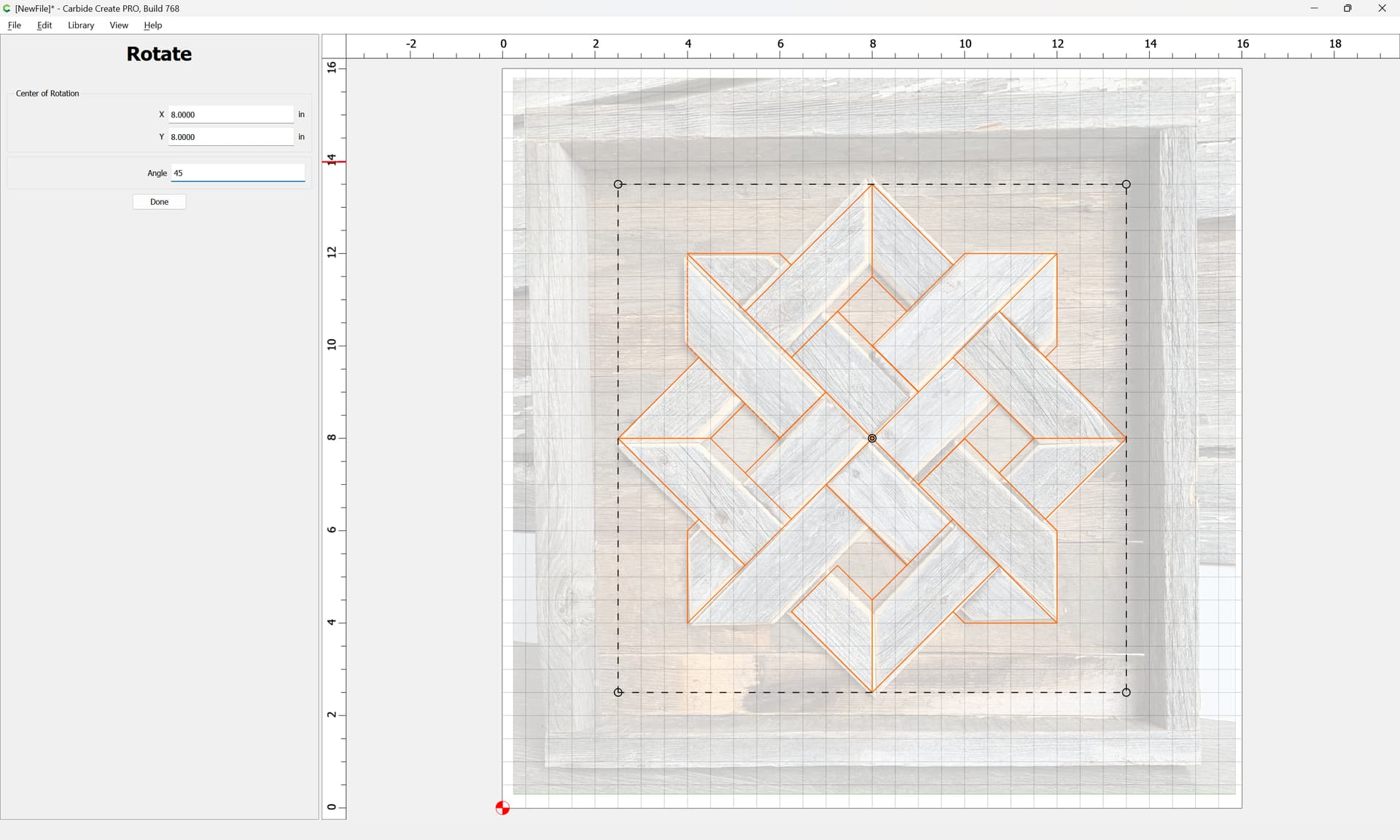
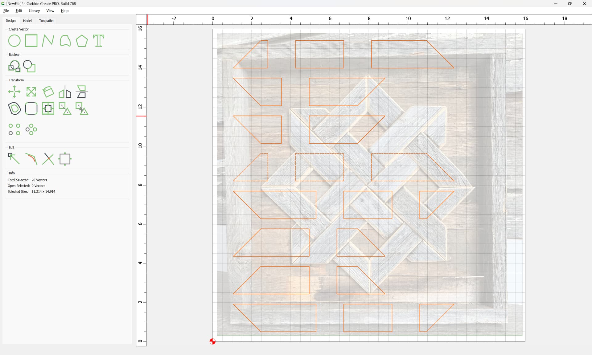
Given a simple design:
re-creating it in Carbide Create is quite straight-forward.
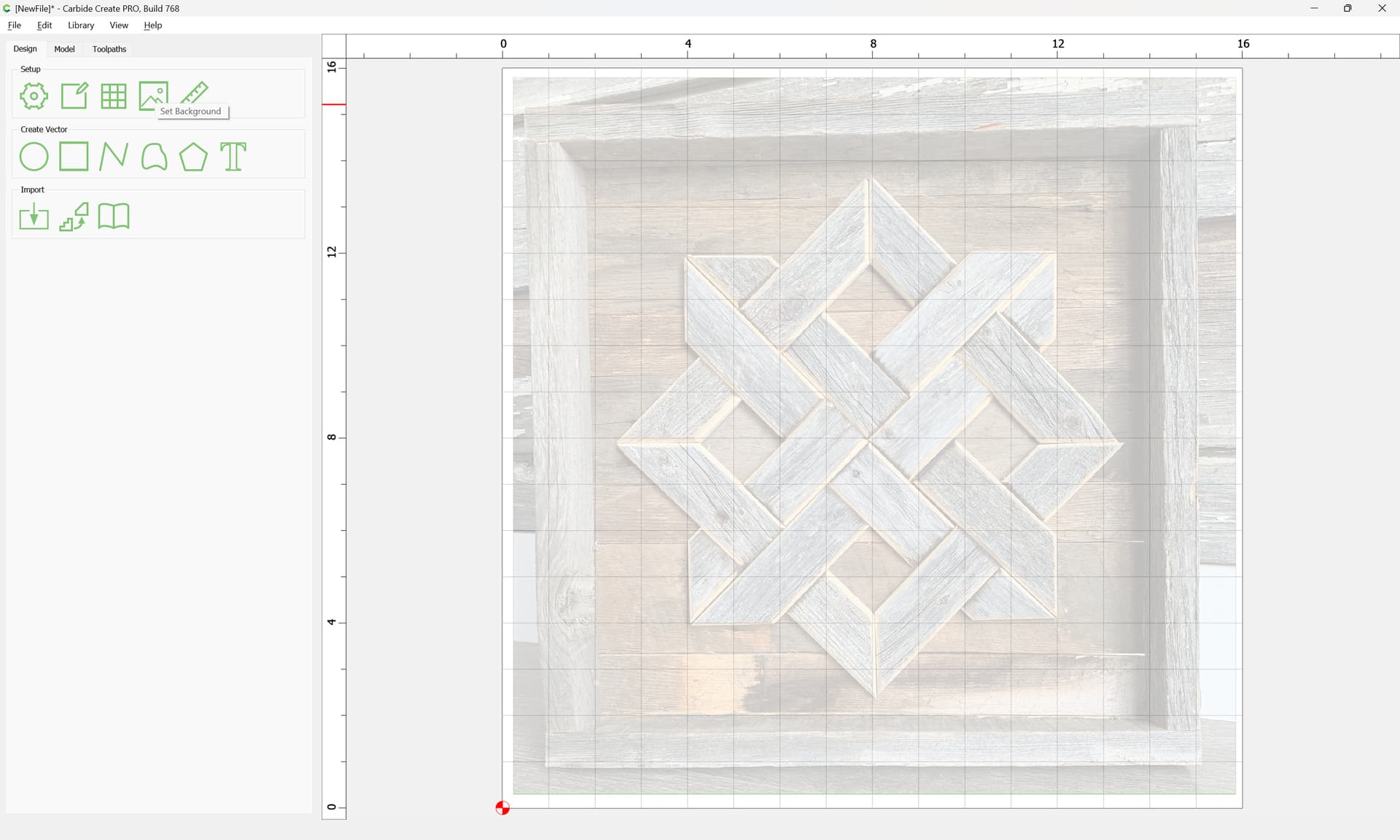
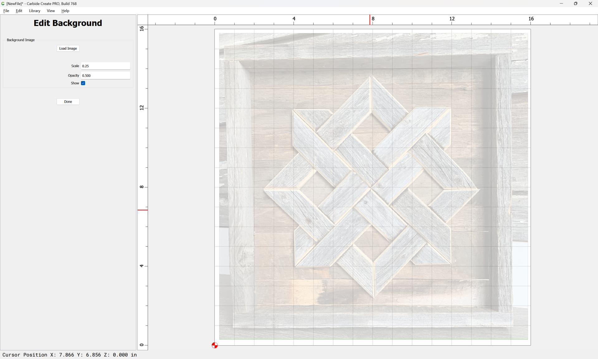
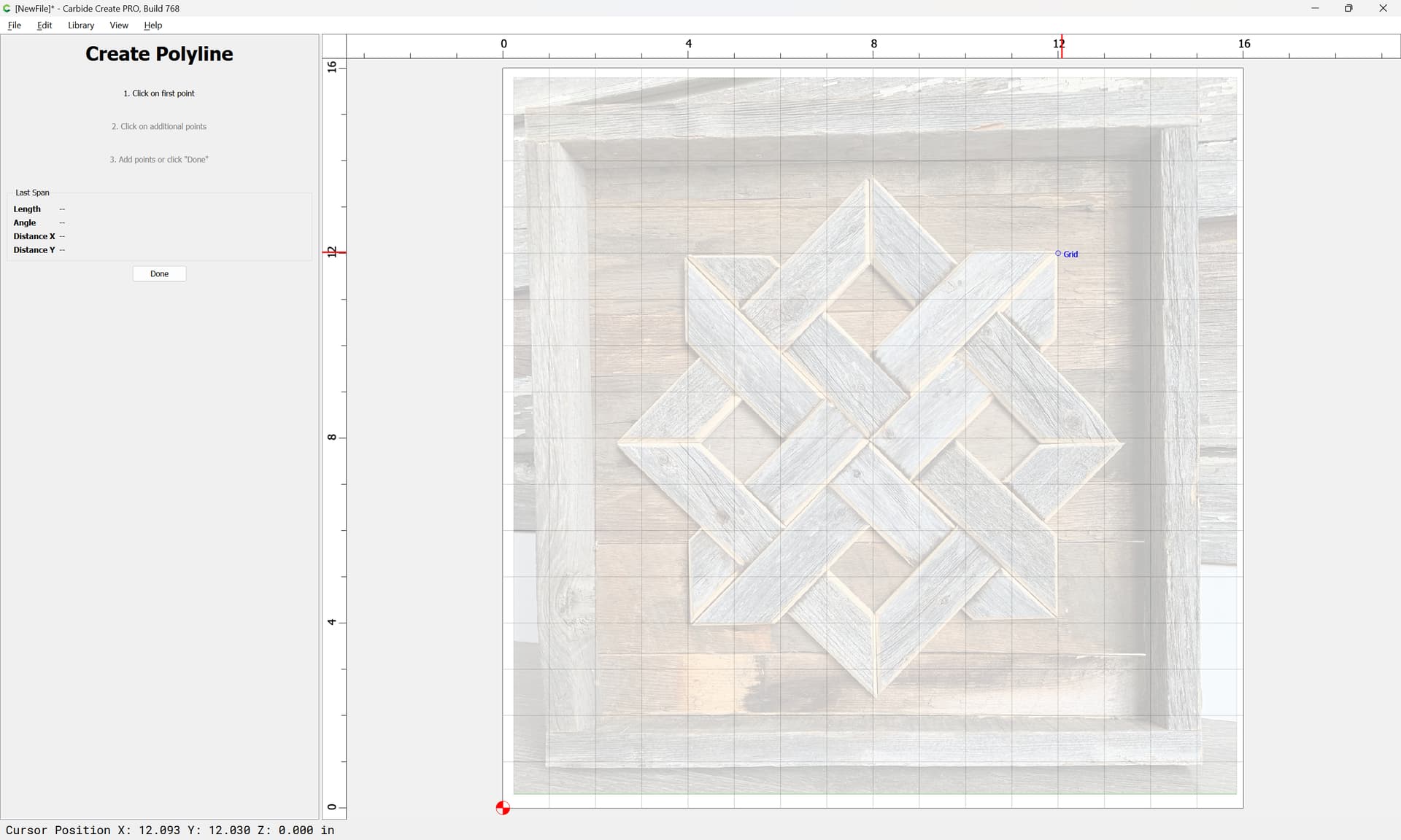
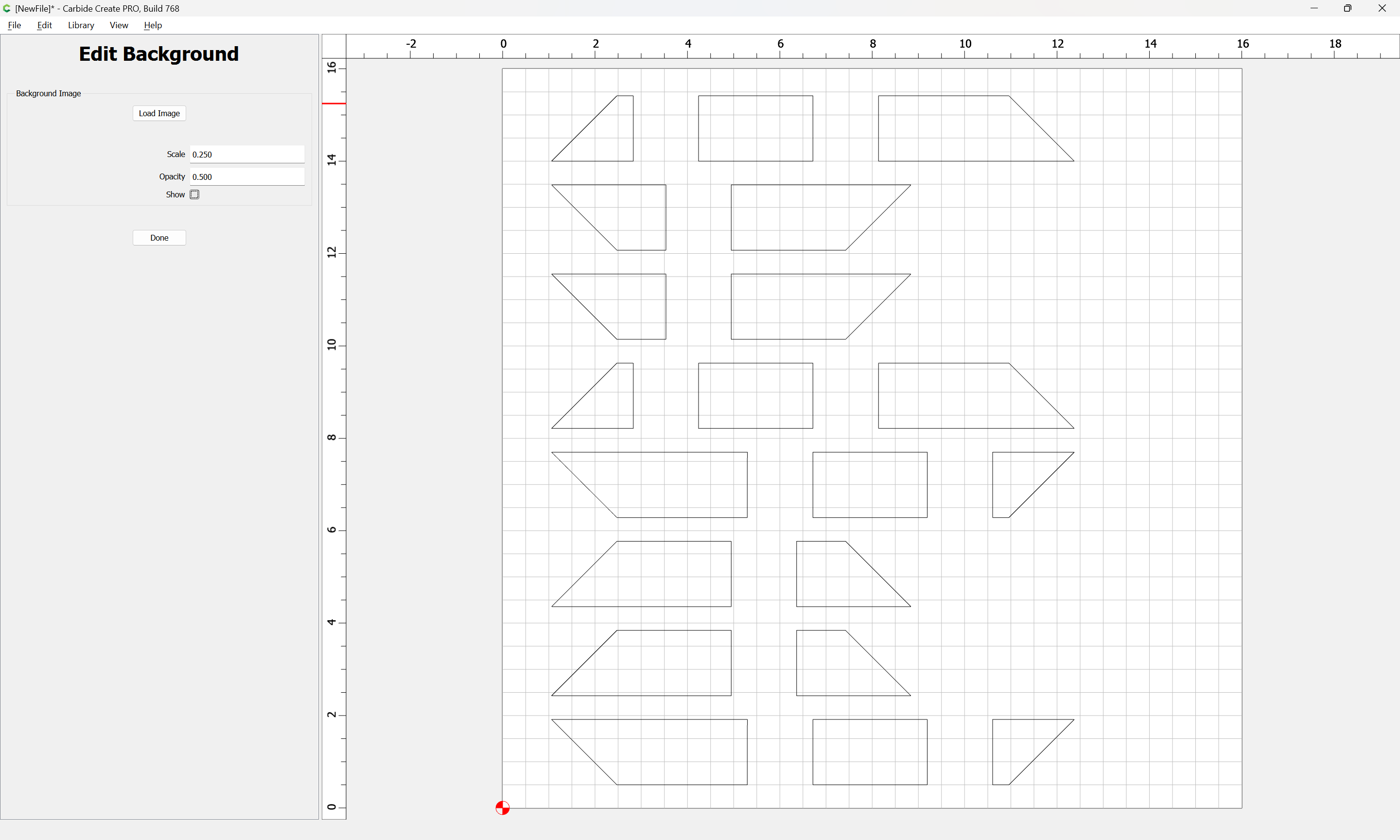
First, import the pixel image as a background reference:
Set Background
Done
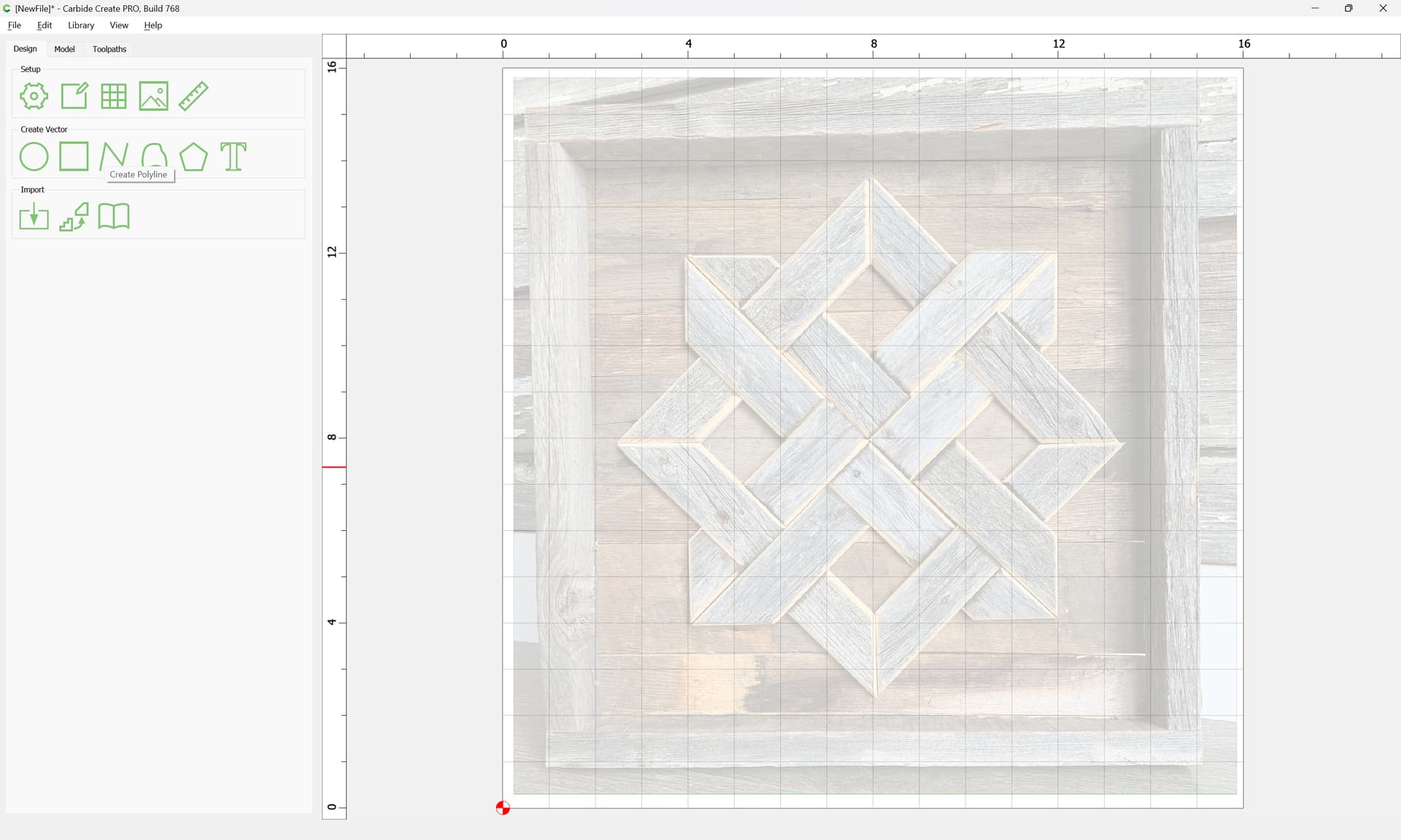
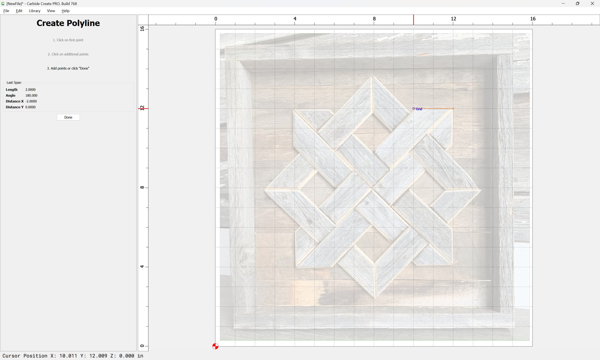
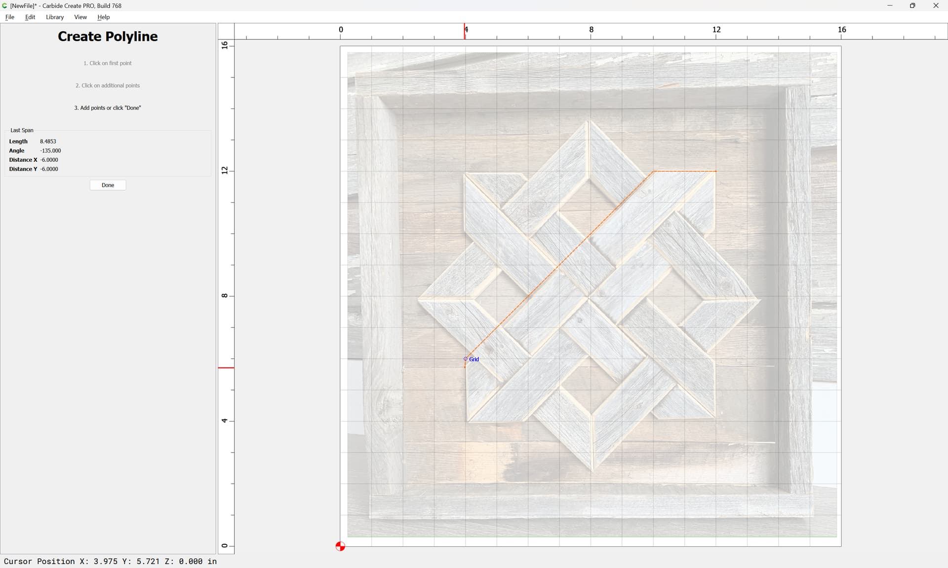
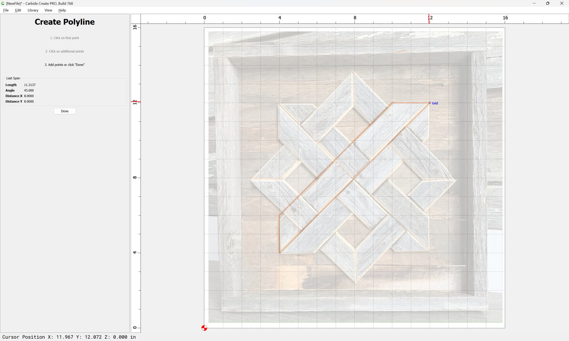
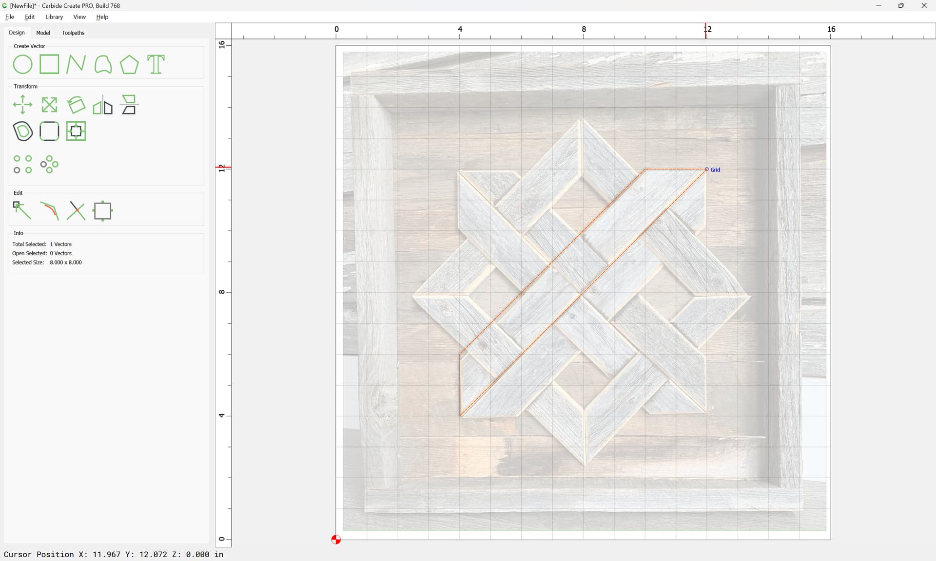
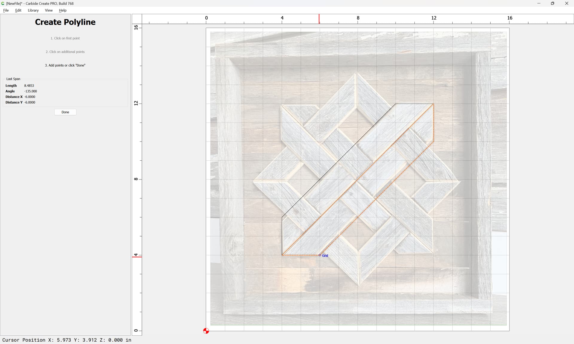
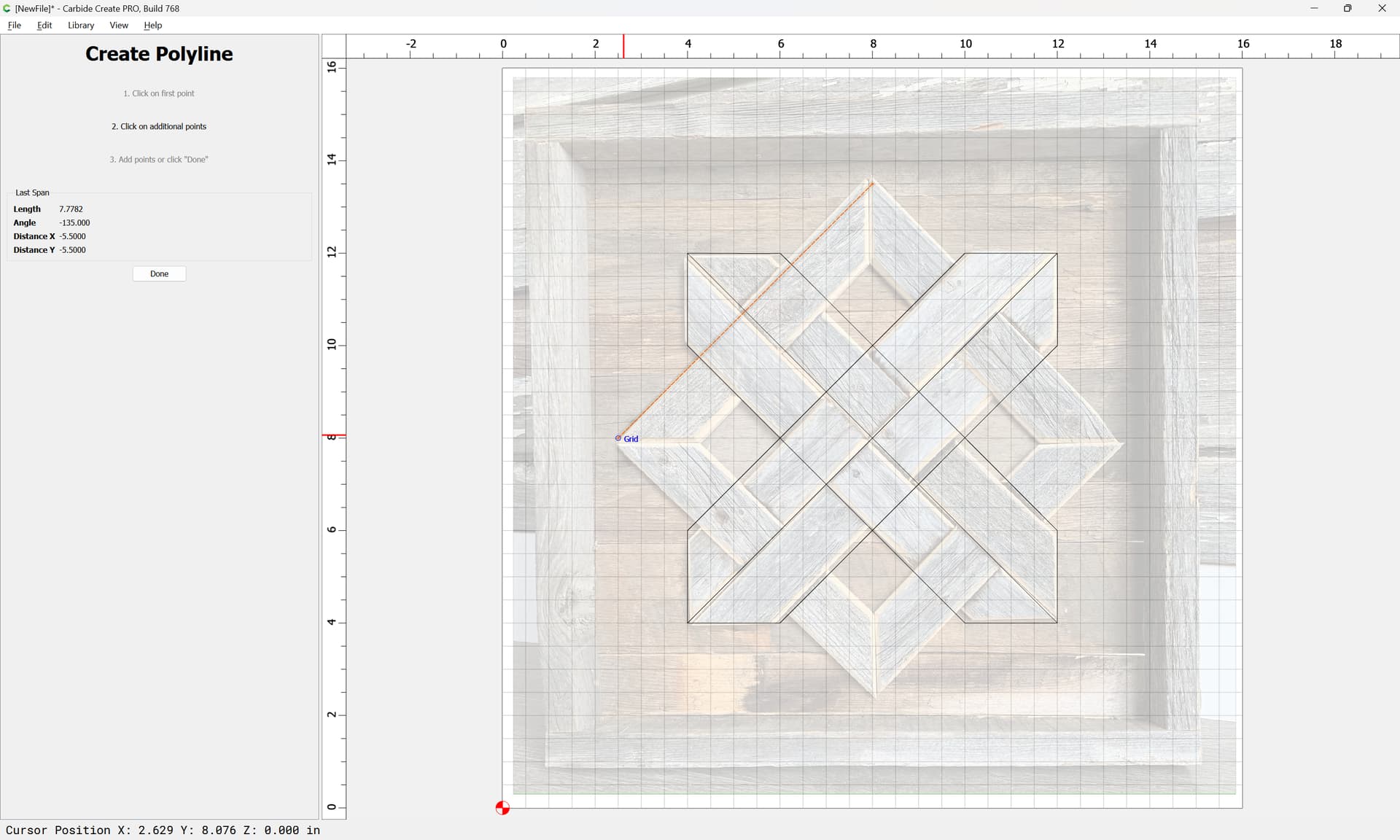
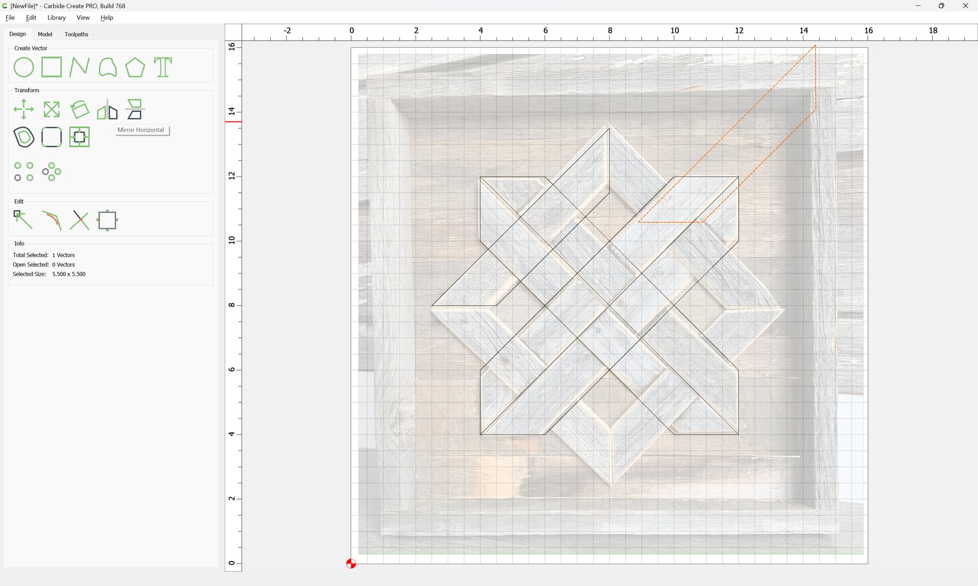
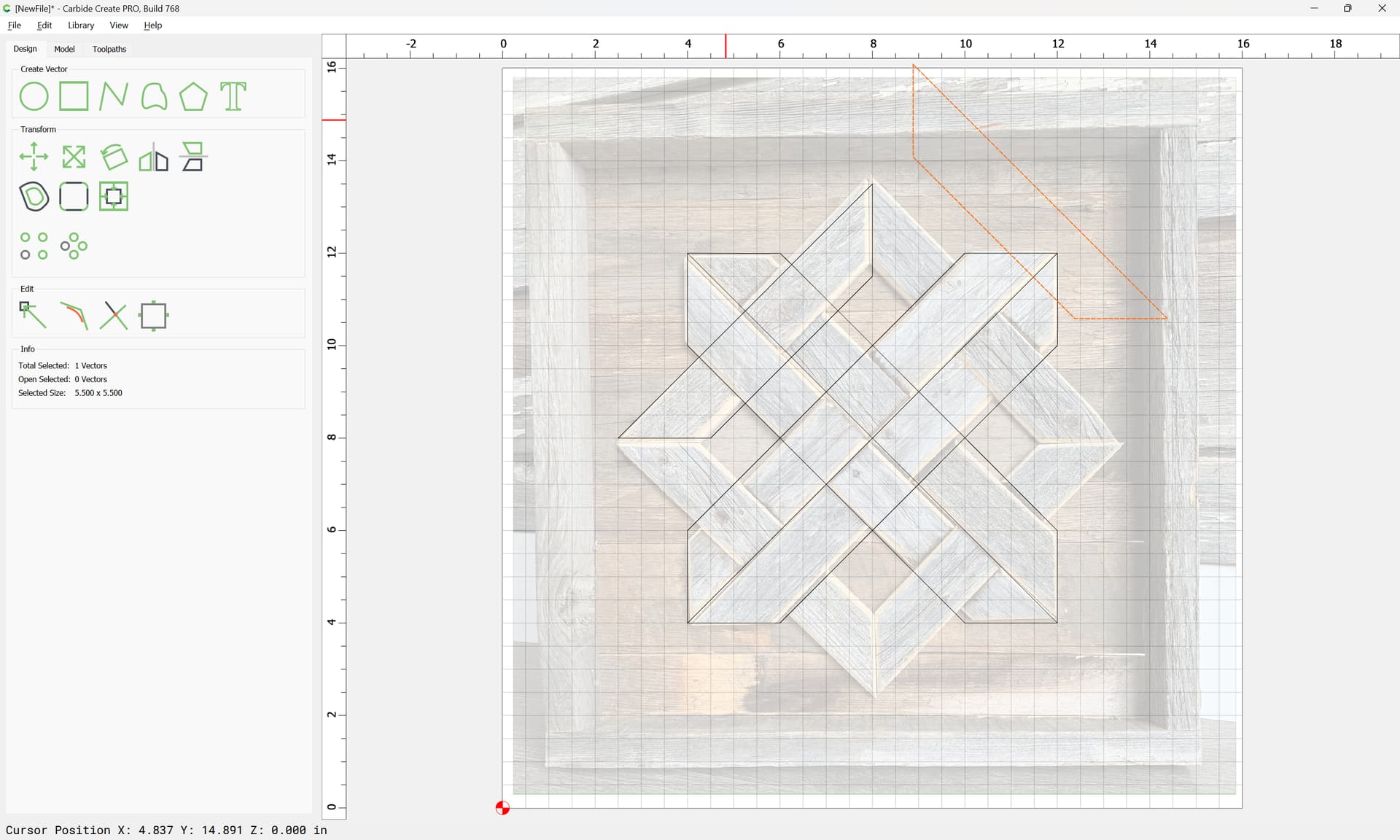
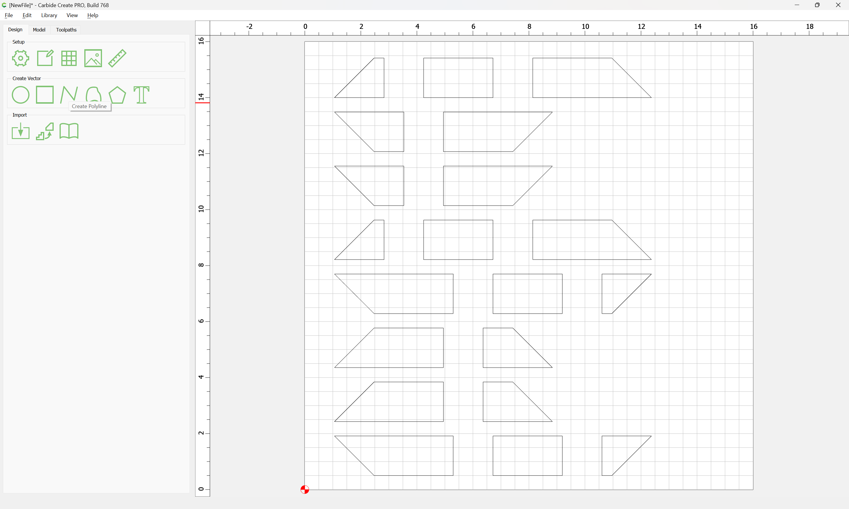
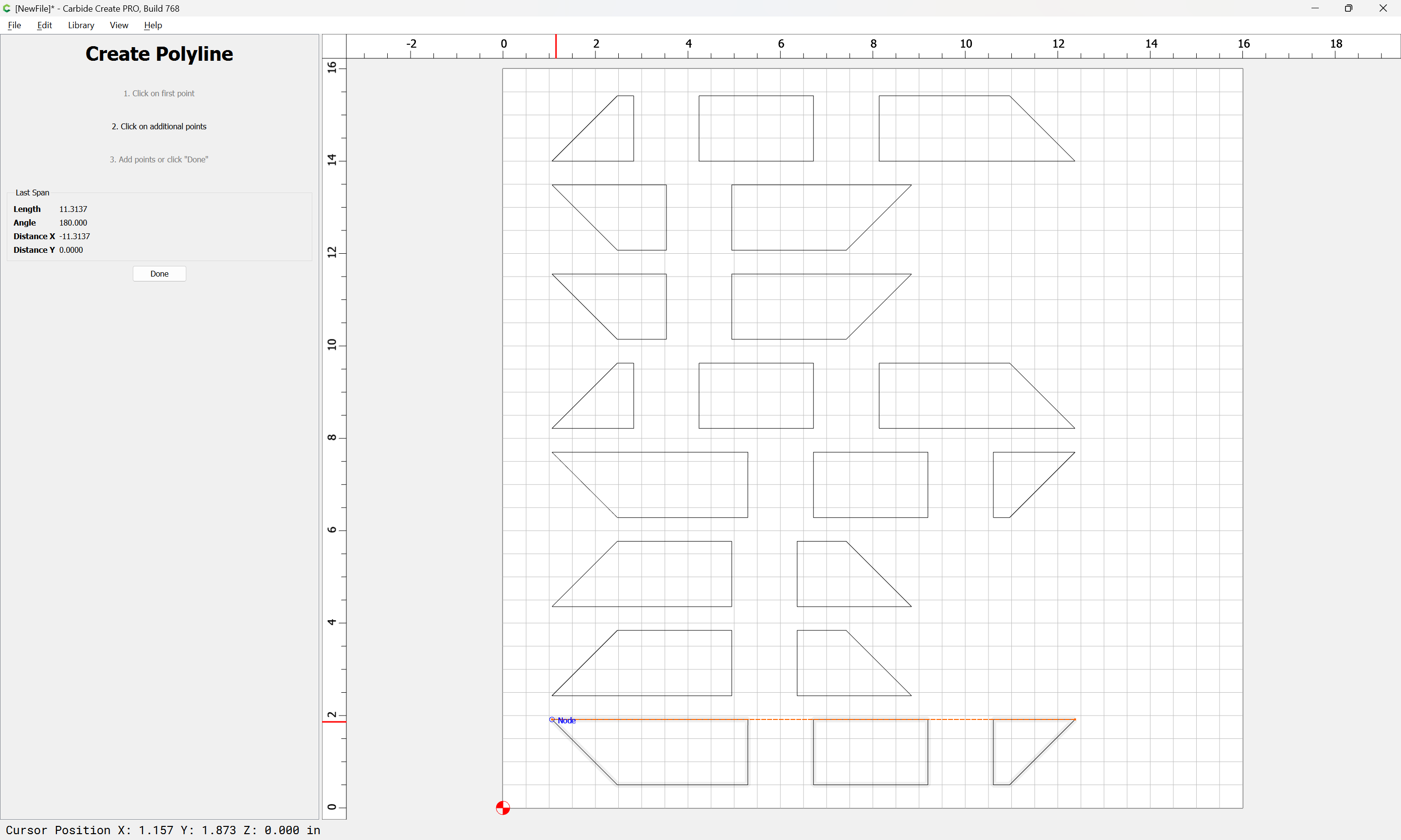
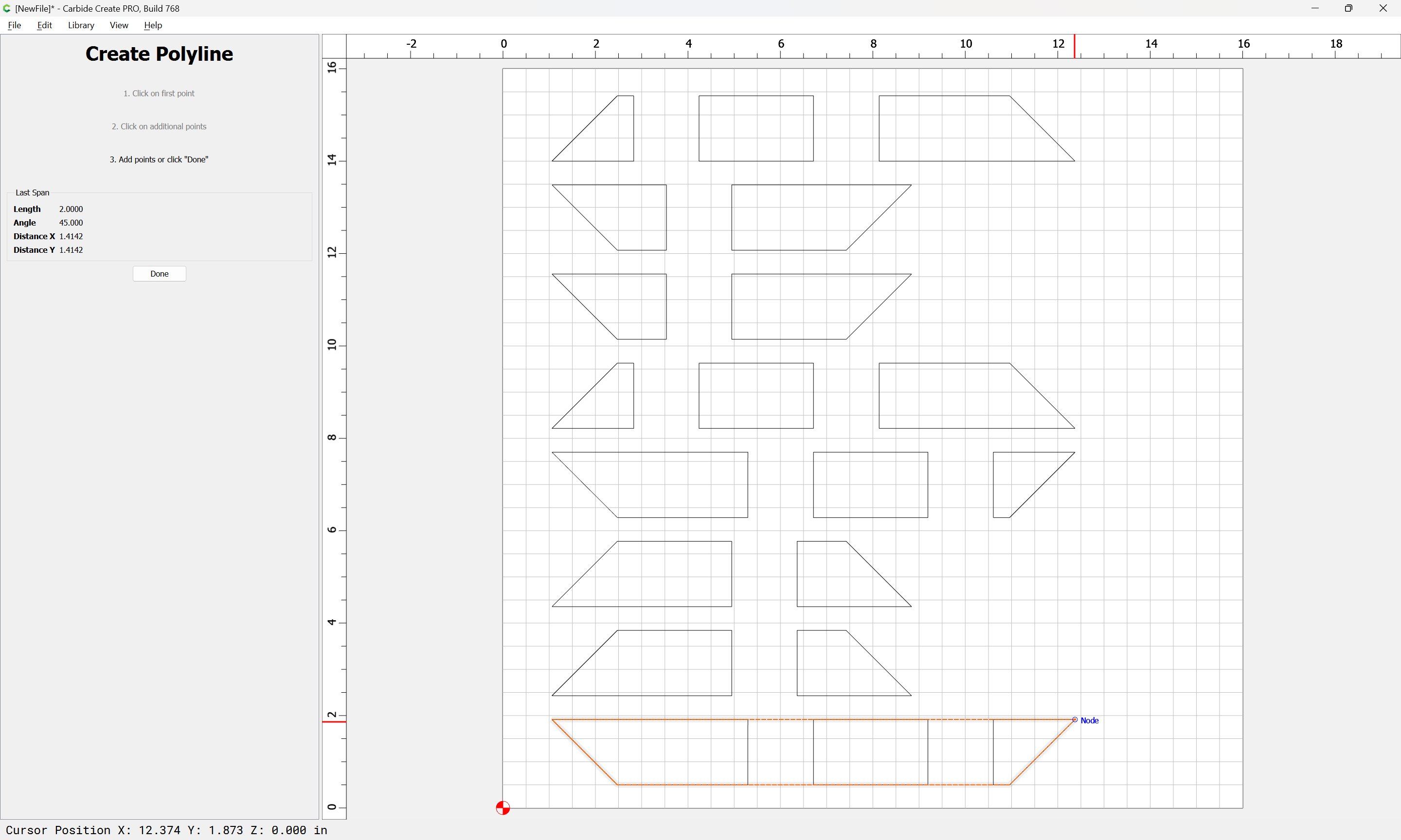
Use the Polyline tool to roughly draw some of the desired geometry:
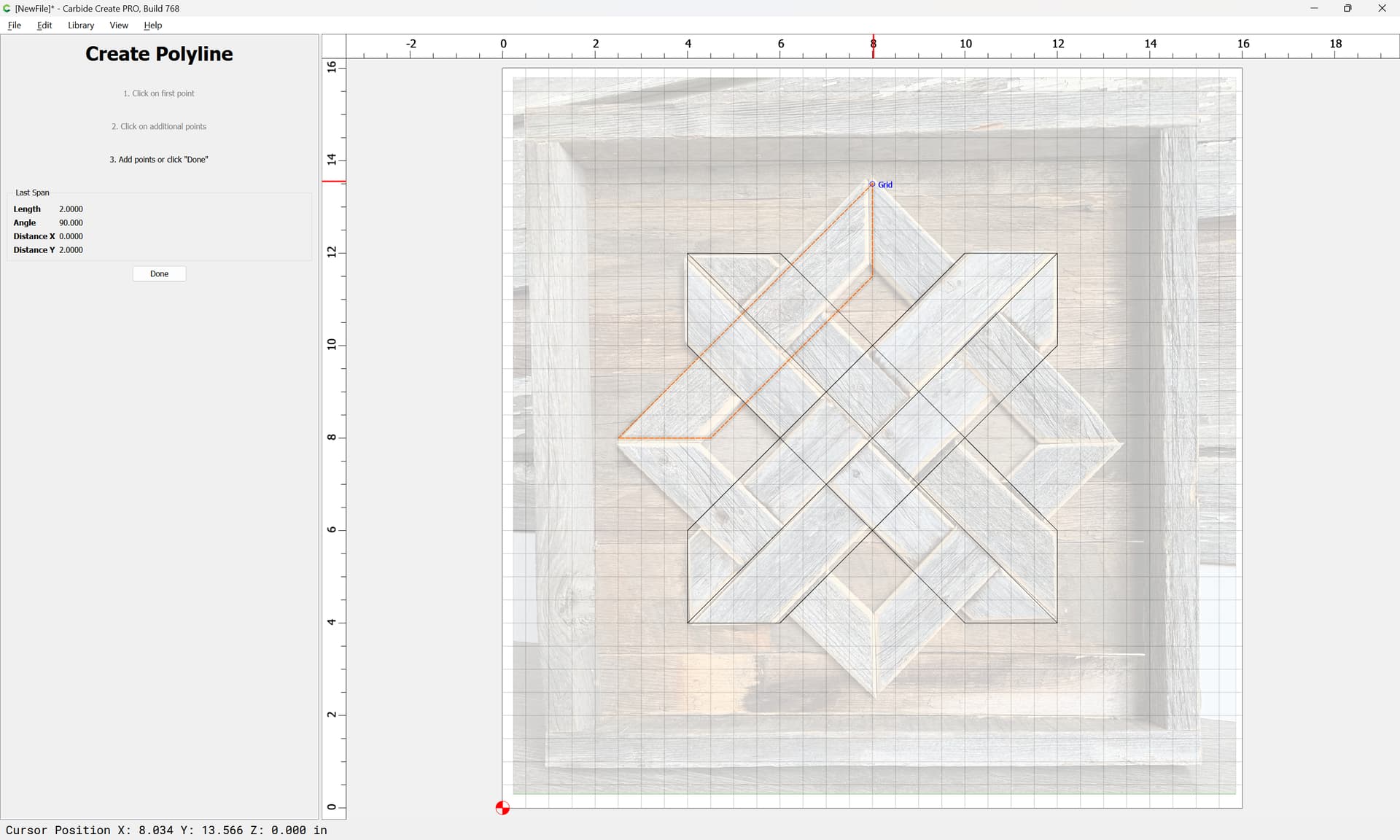
and repeat for all the shapes involved:
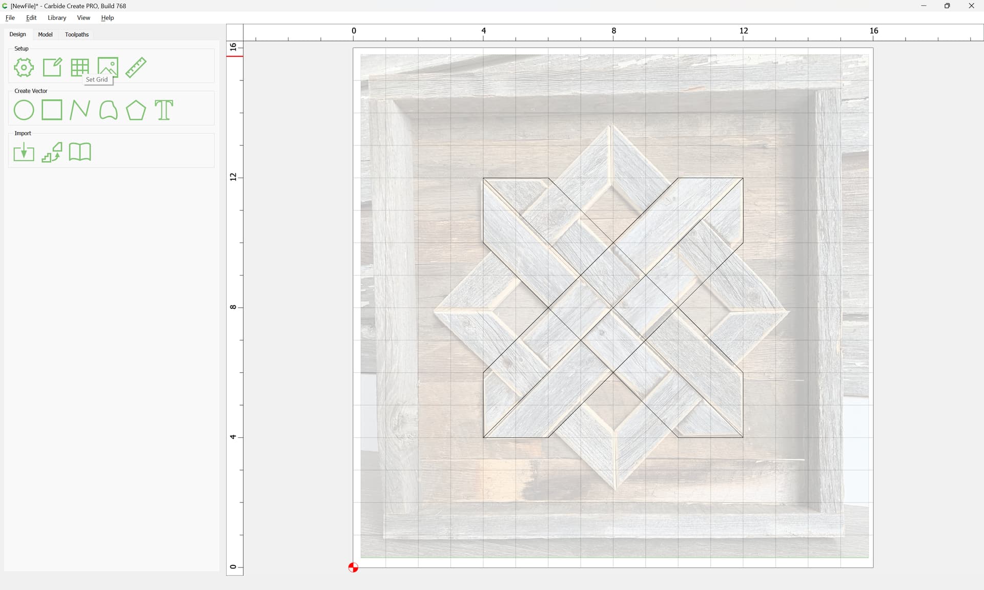
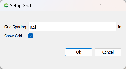
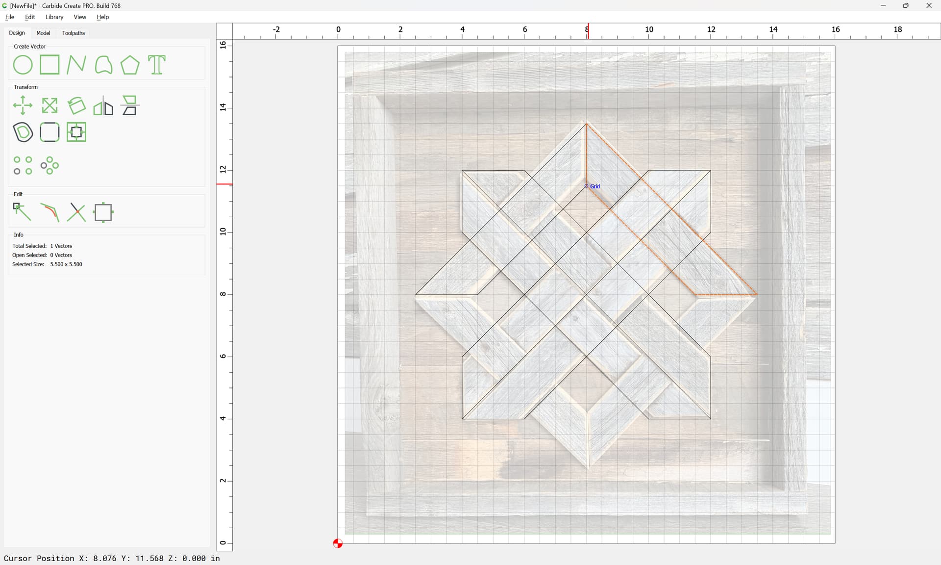
If need be, adjust the Grid size:
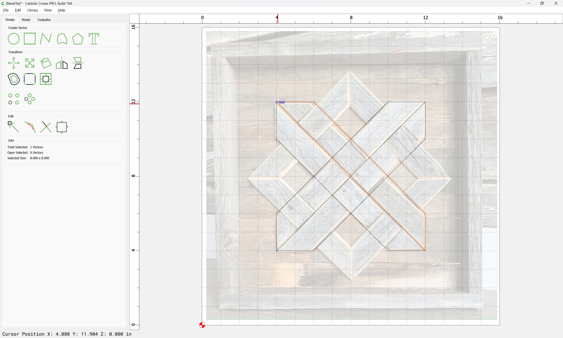
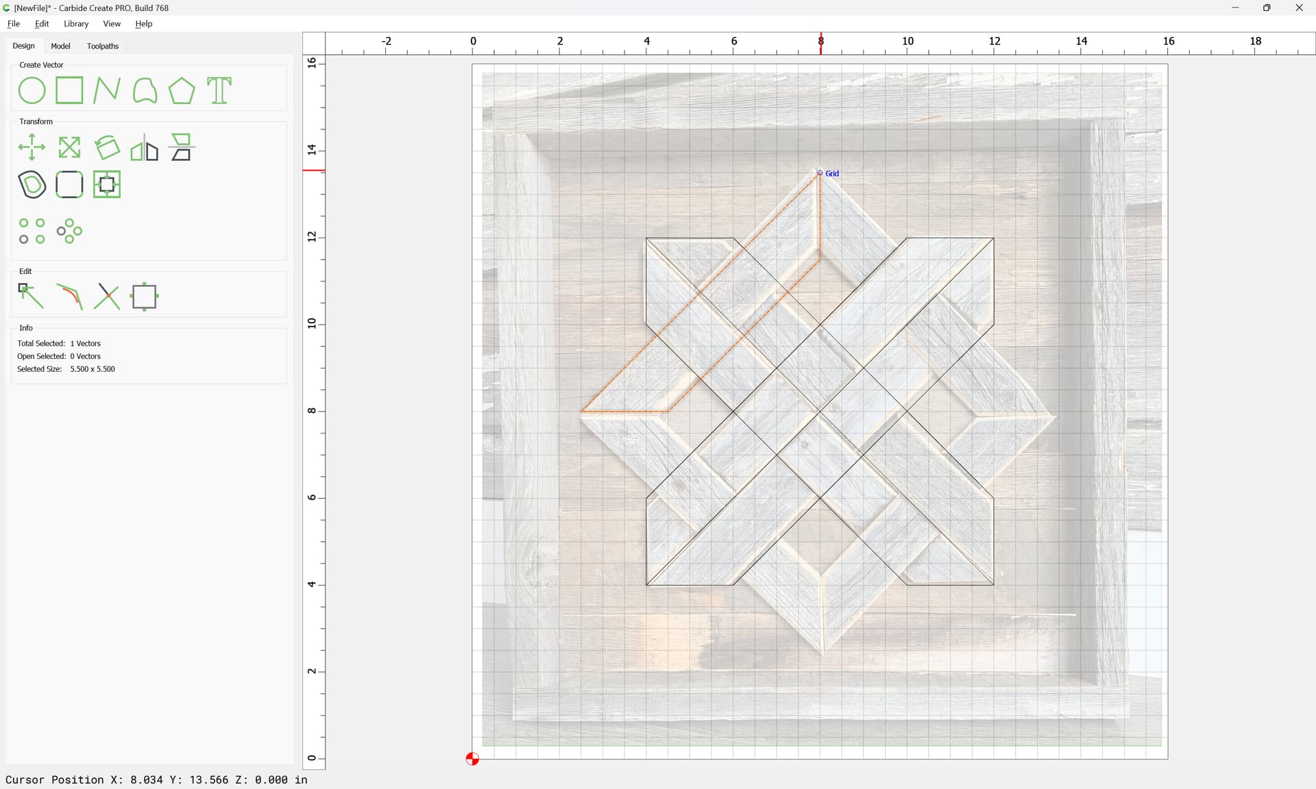
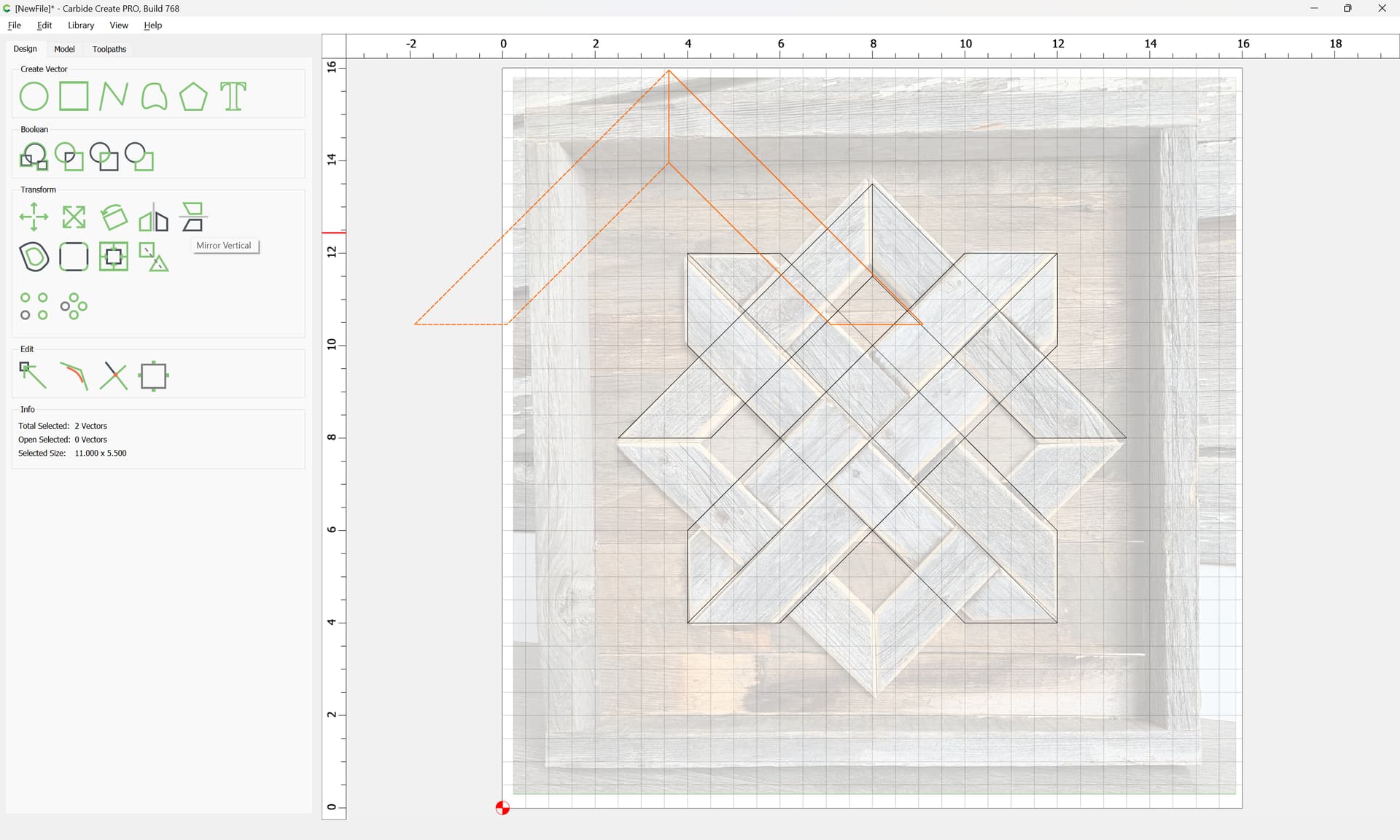
Since the design is symmetrical, once one part is made it may be copy-pasted:
and then mirrored and dragged into position:
and this process repeated:
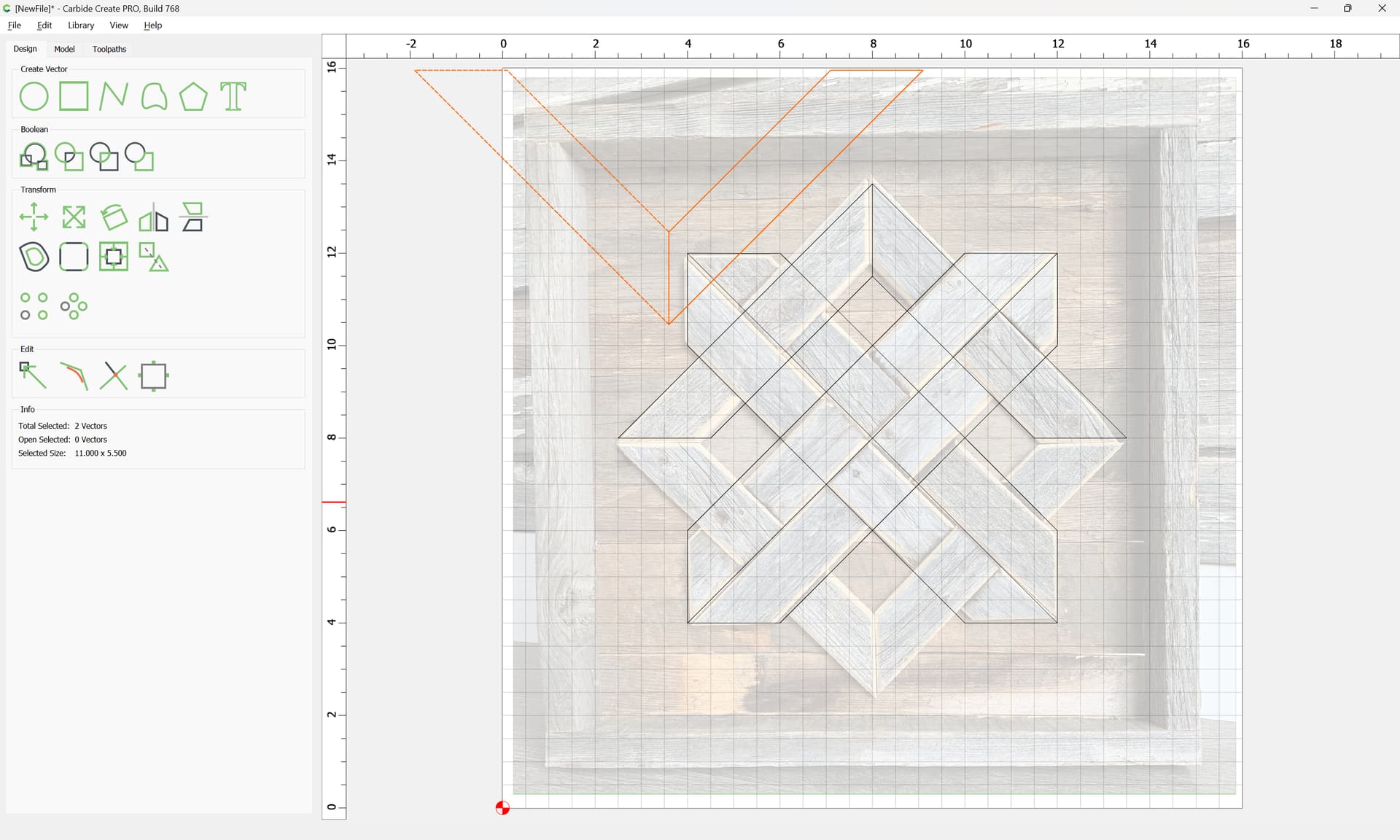
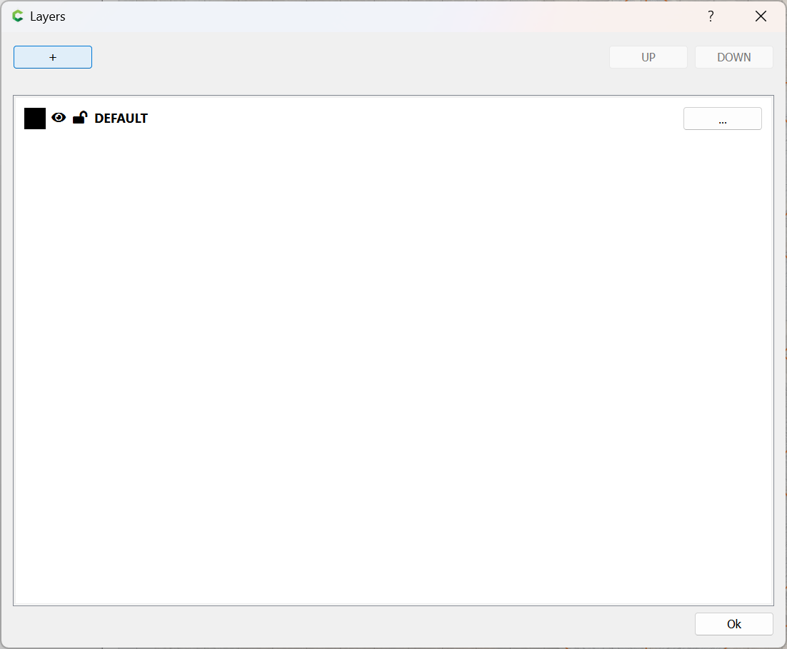
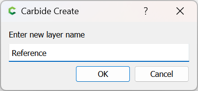
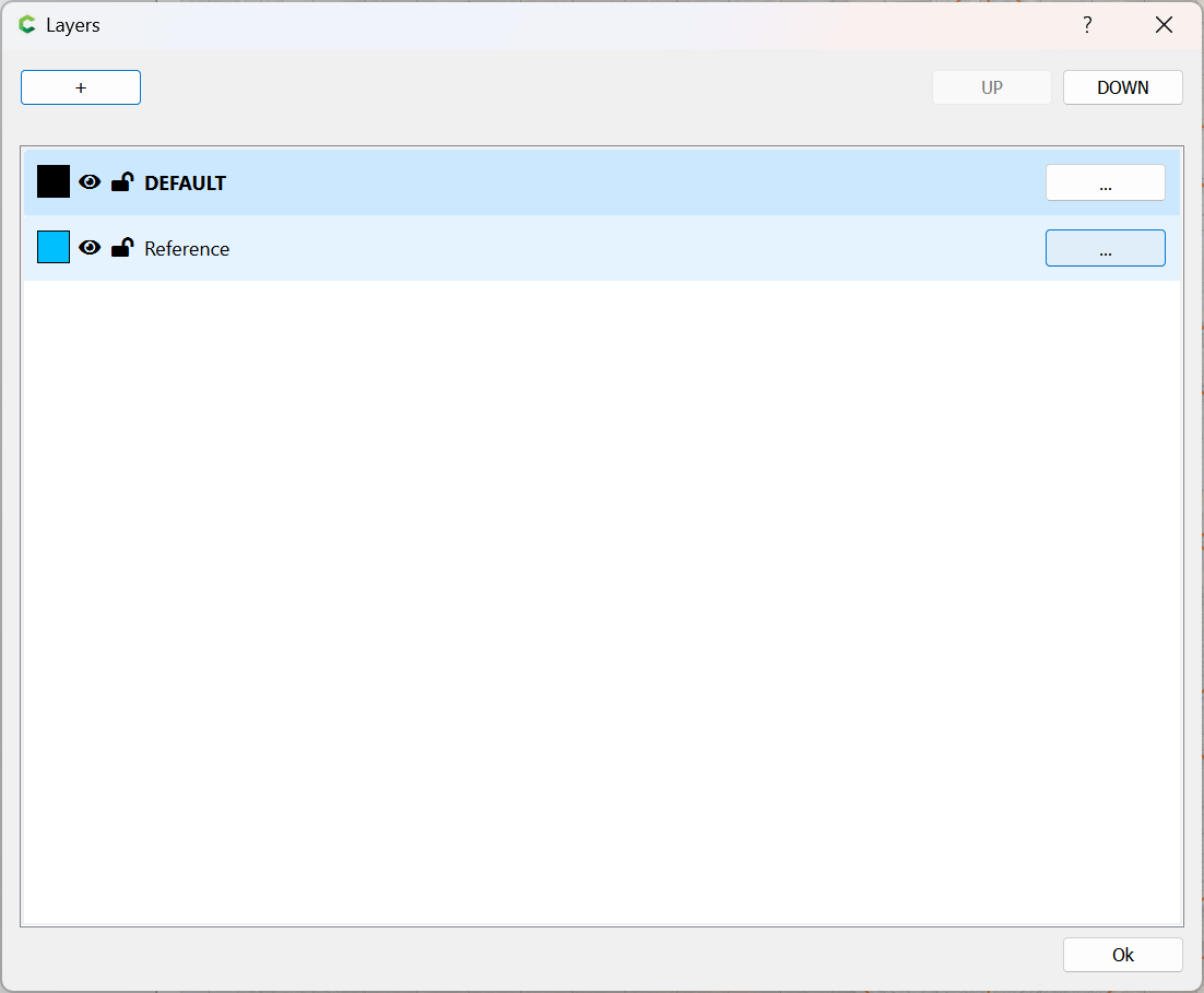
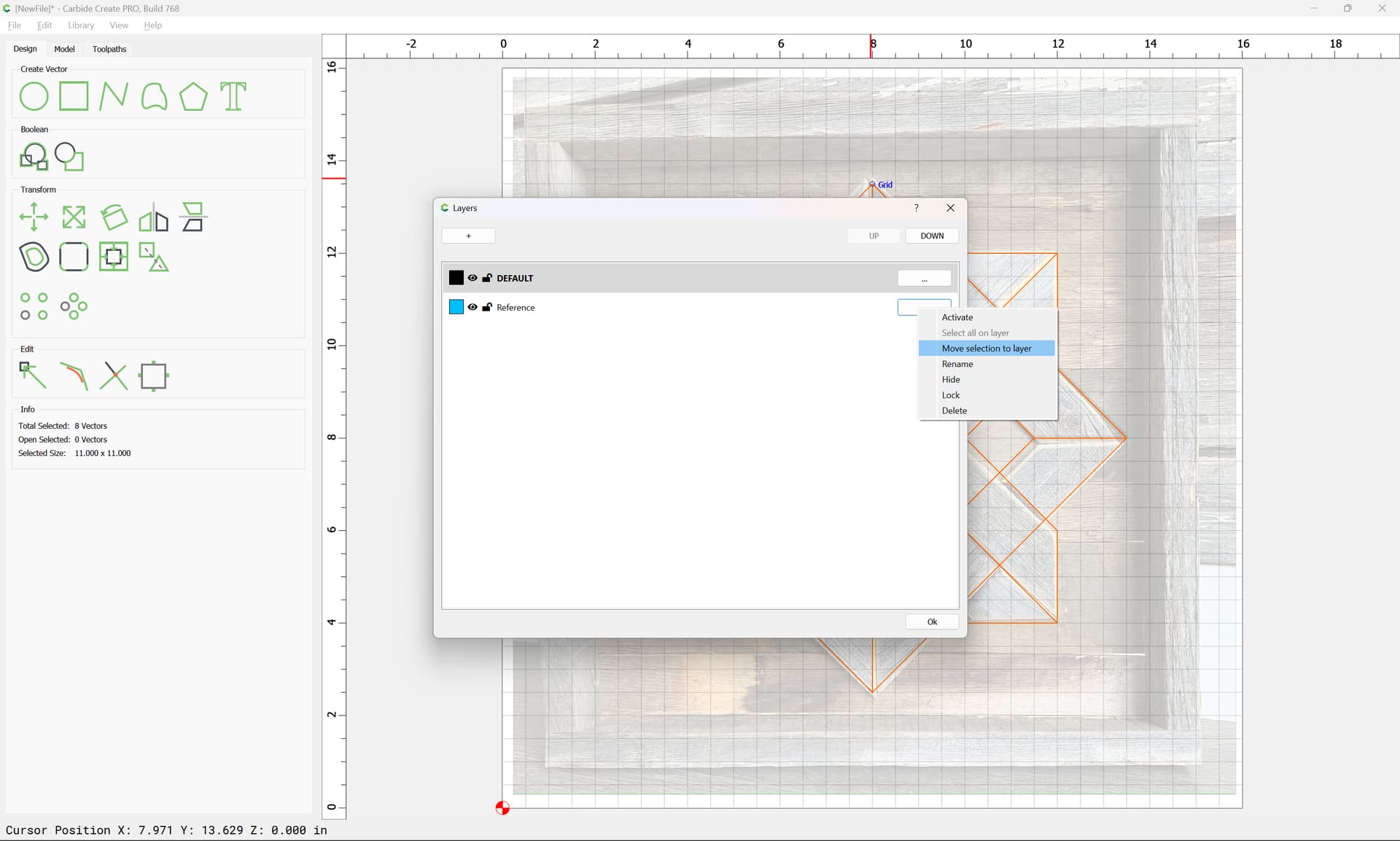
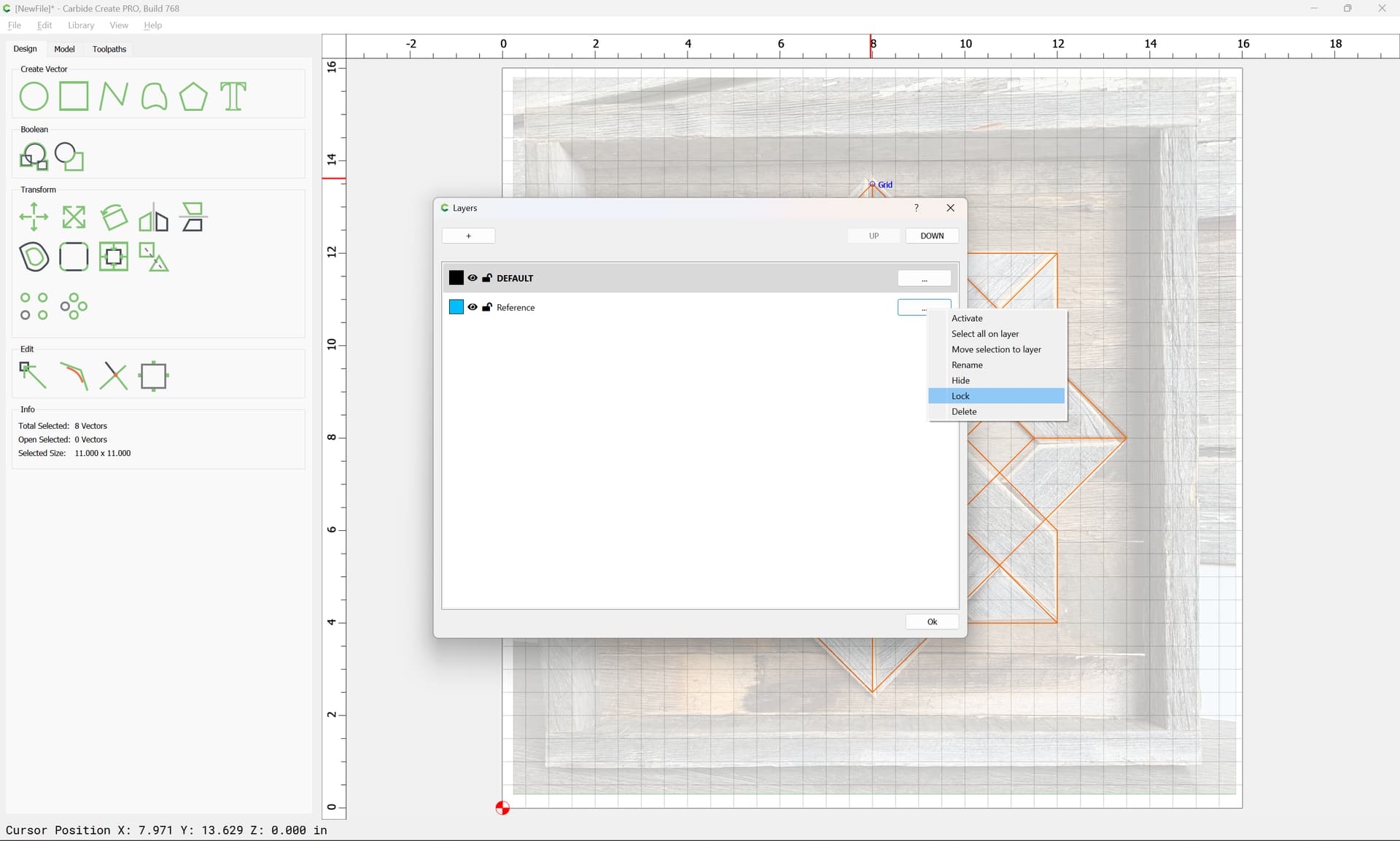
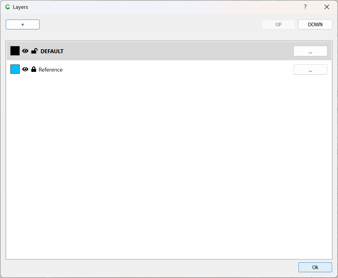
At this point, the geometry may be duplicated and placed on a reference layer:
Ok
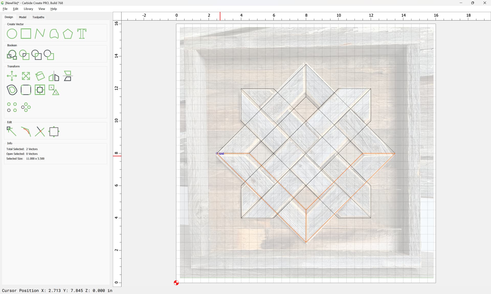
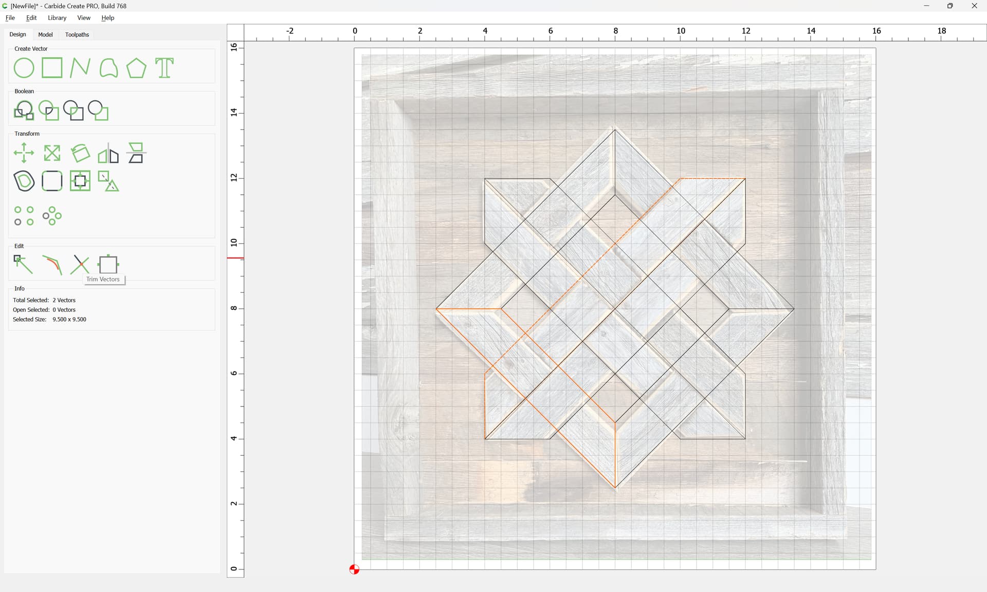
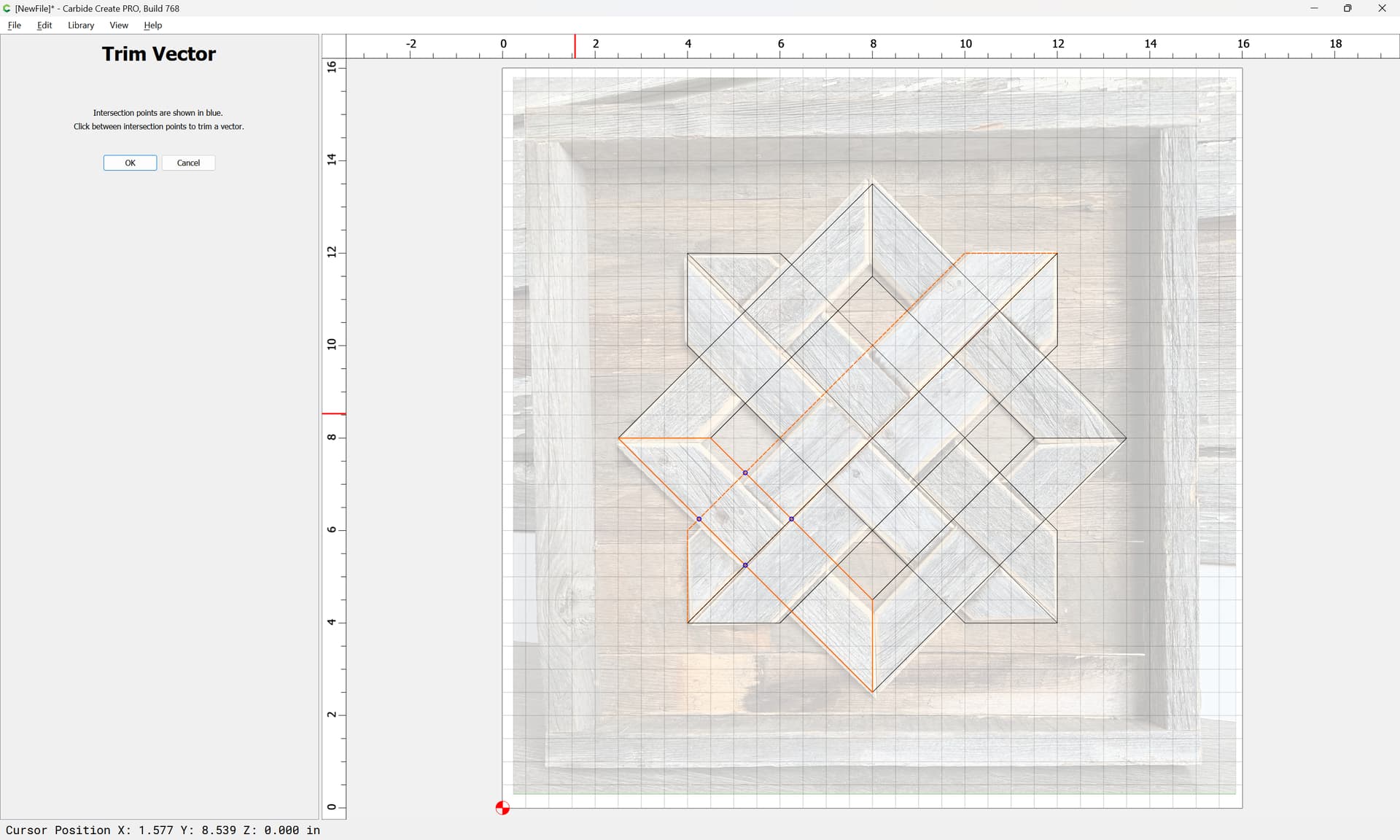
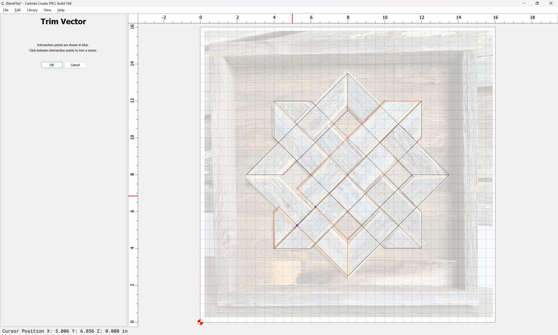
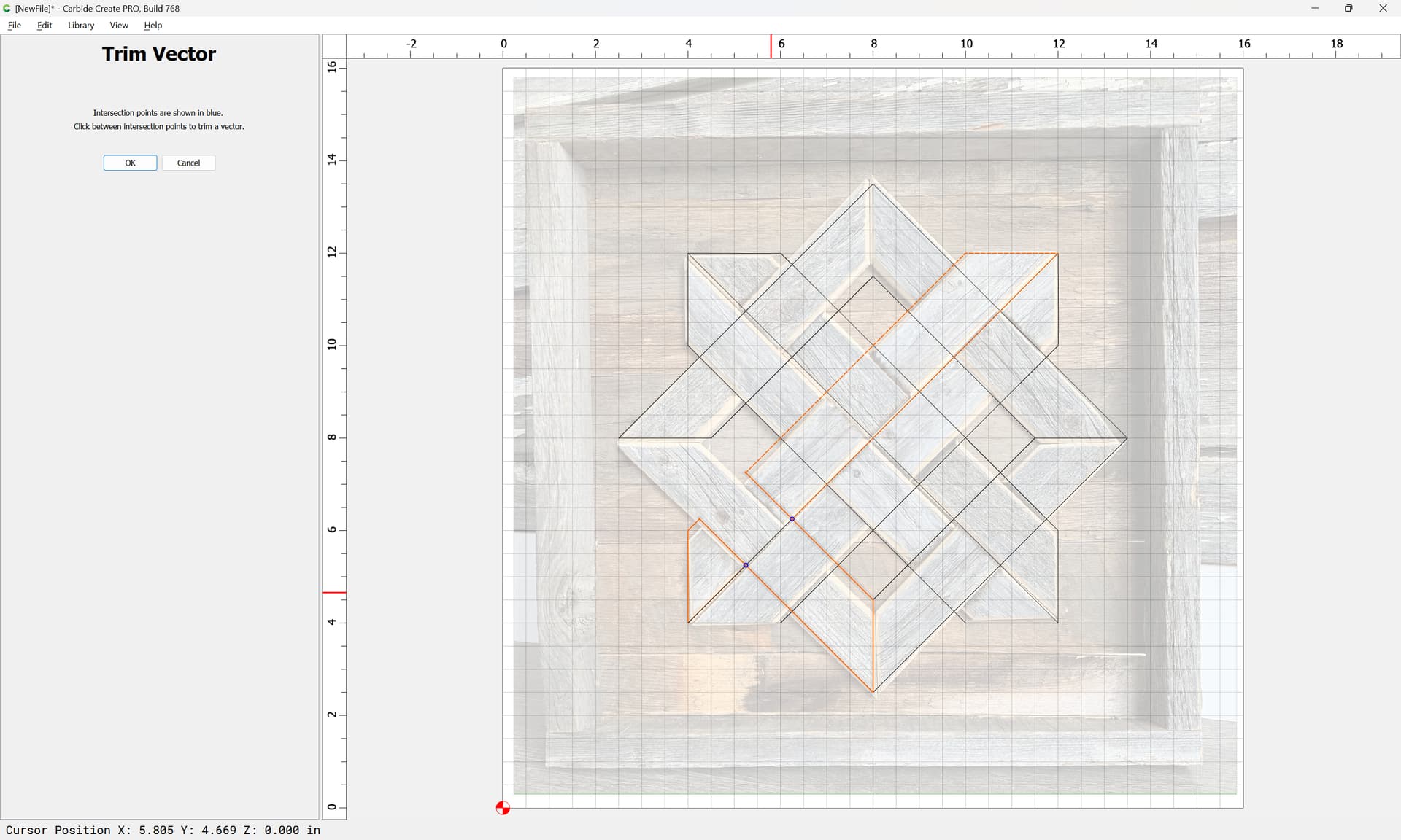
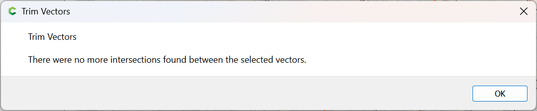
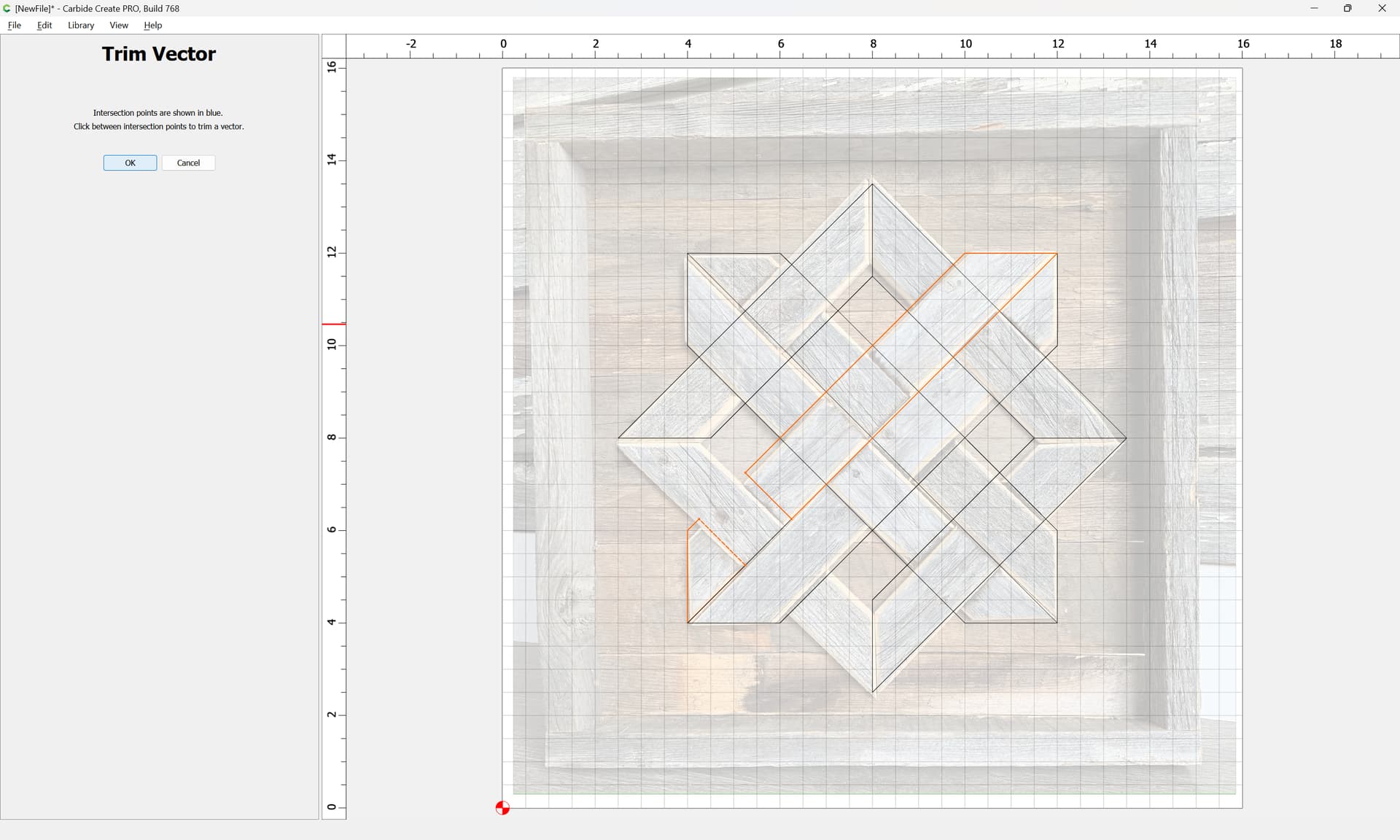
For any given part, use Trim Vectors:
OK
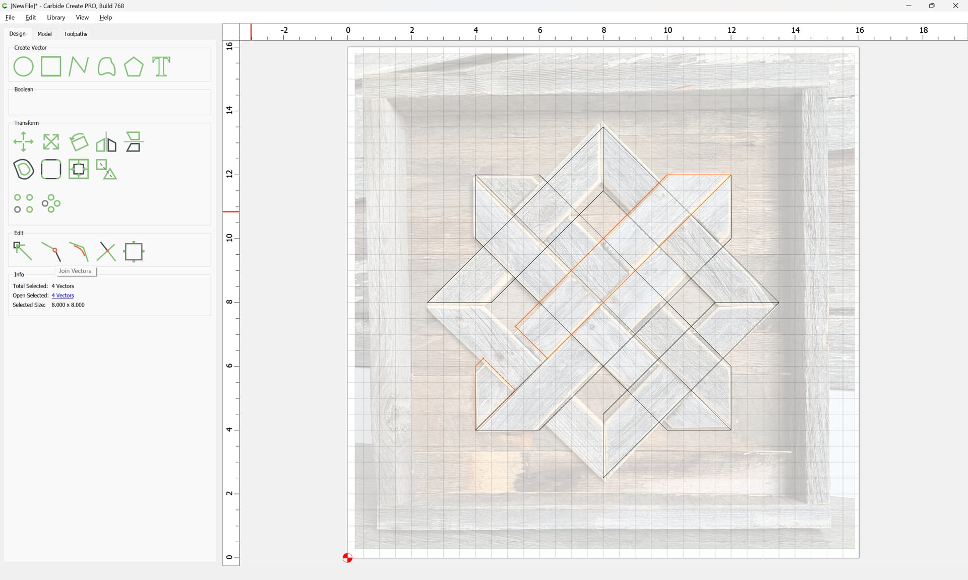
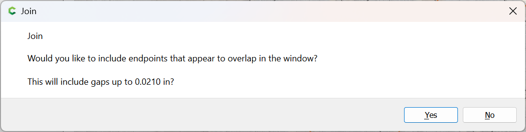
Then use Join Vectors to close the elements:
Yes
Then repeat for each part…
1 Like
WillAdams
March 6, 2024, 11:26pm
2
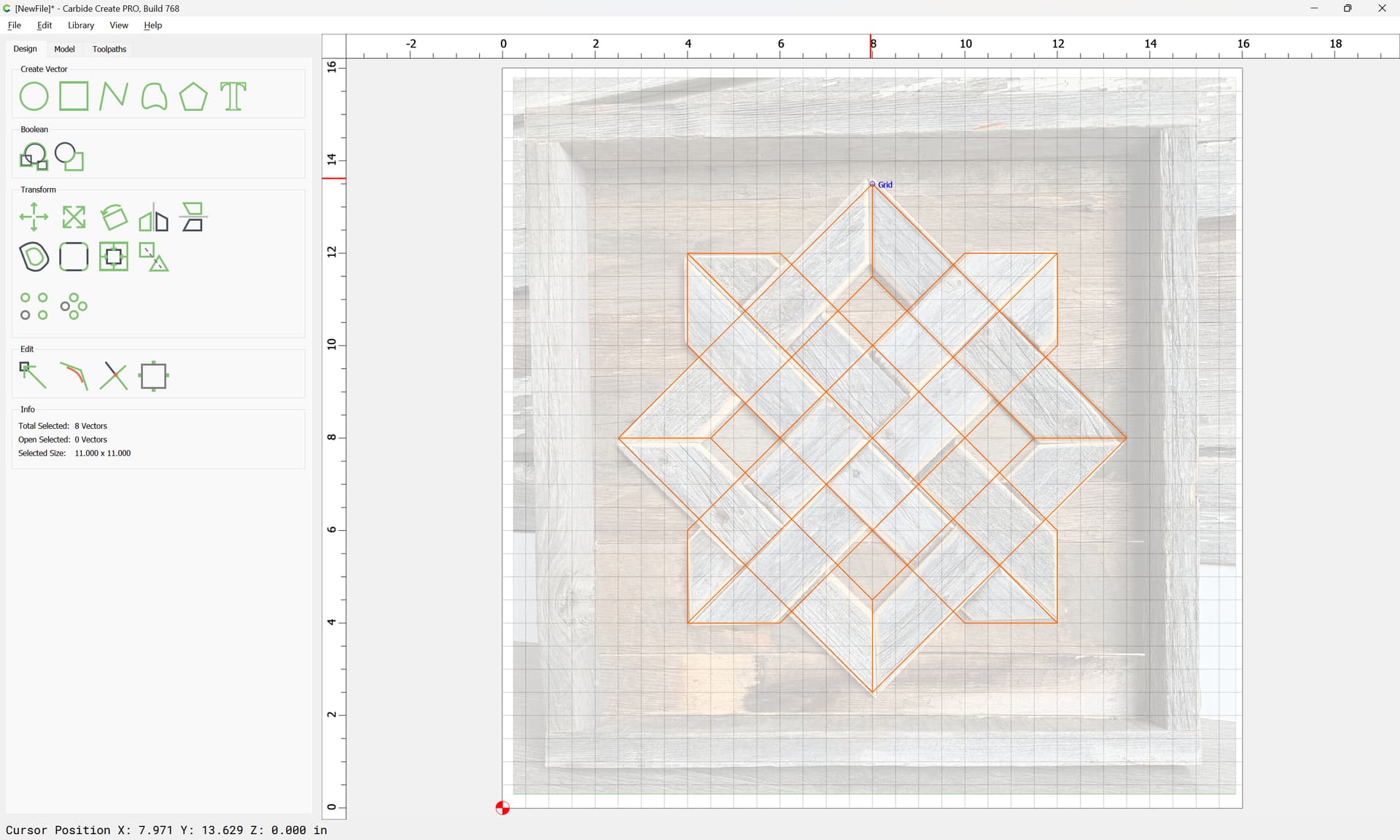
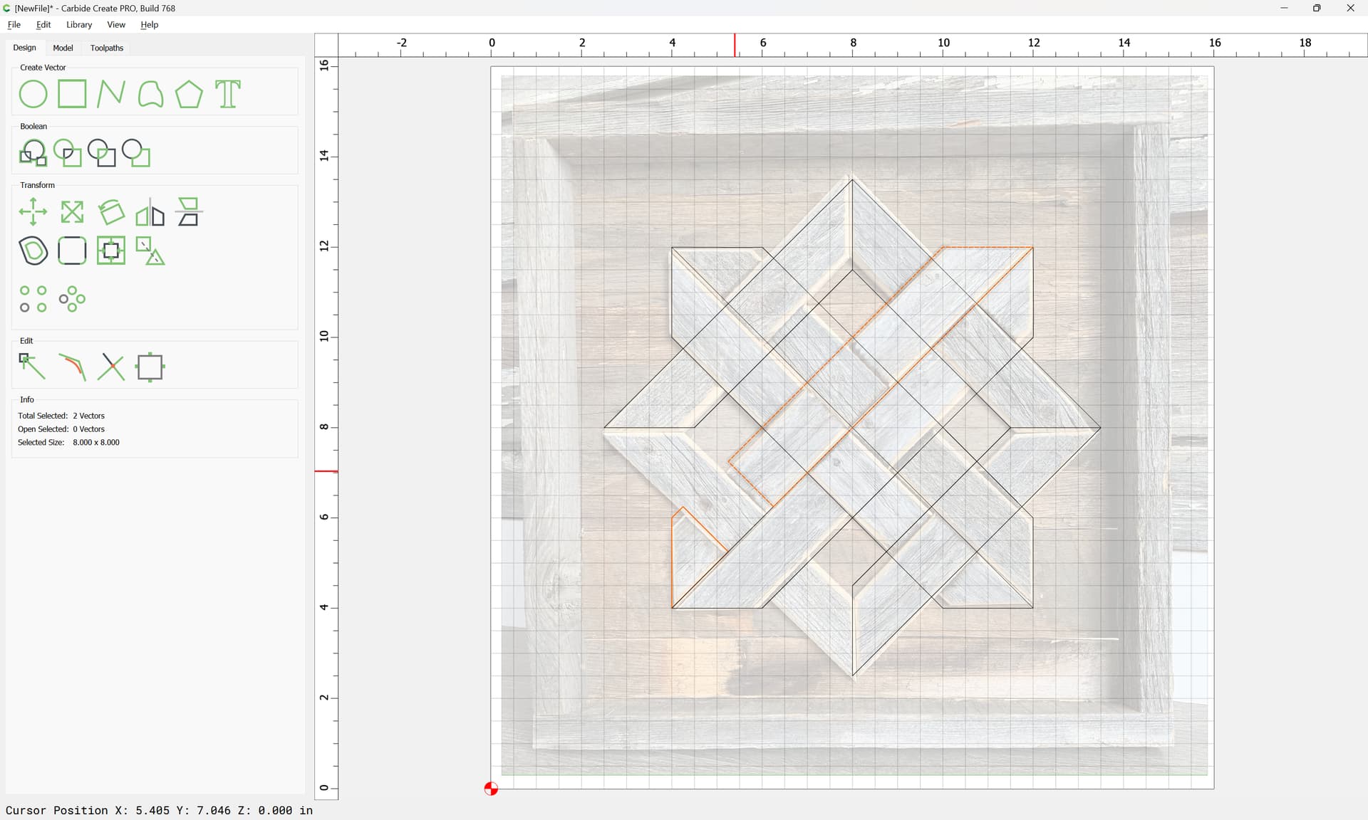
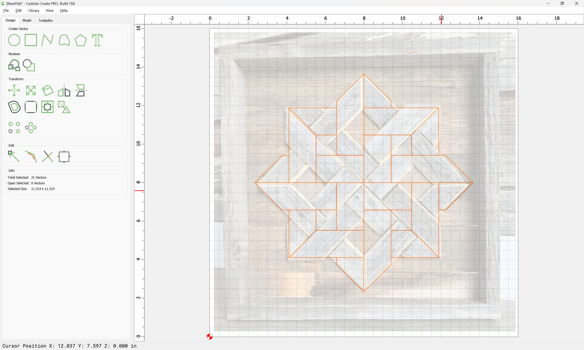
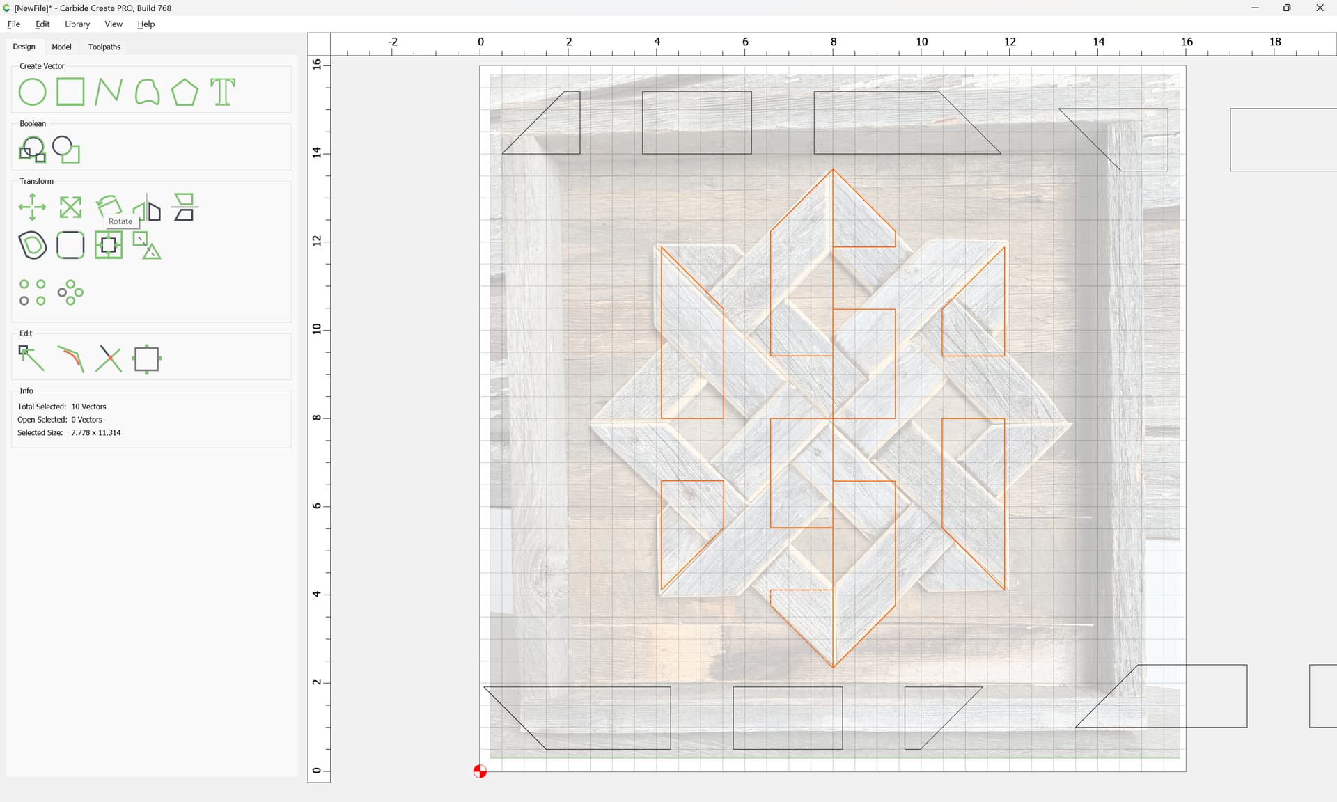
Eventually arriving at:
…as requested on support…
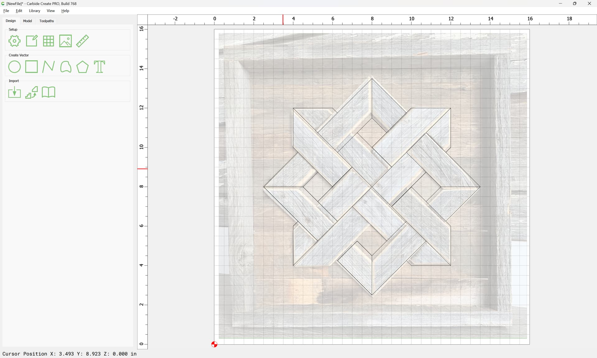
Then select all the geometry and rotate it 45 degrees:
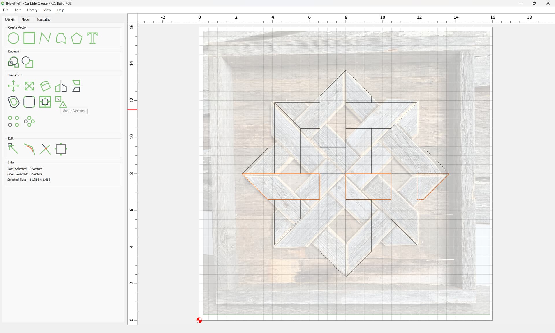
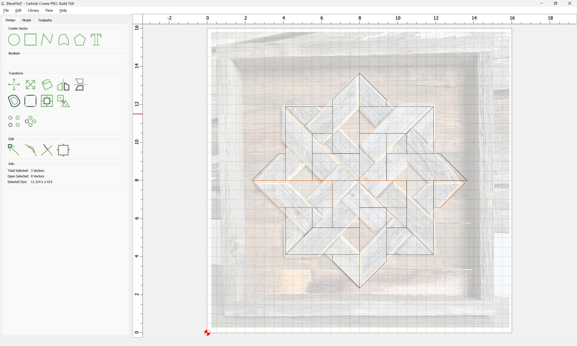
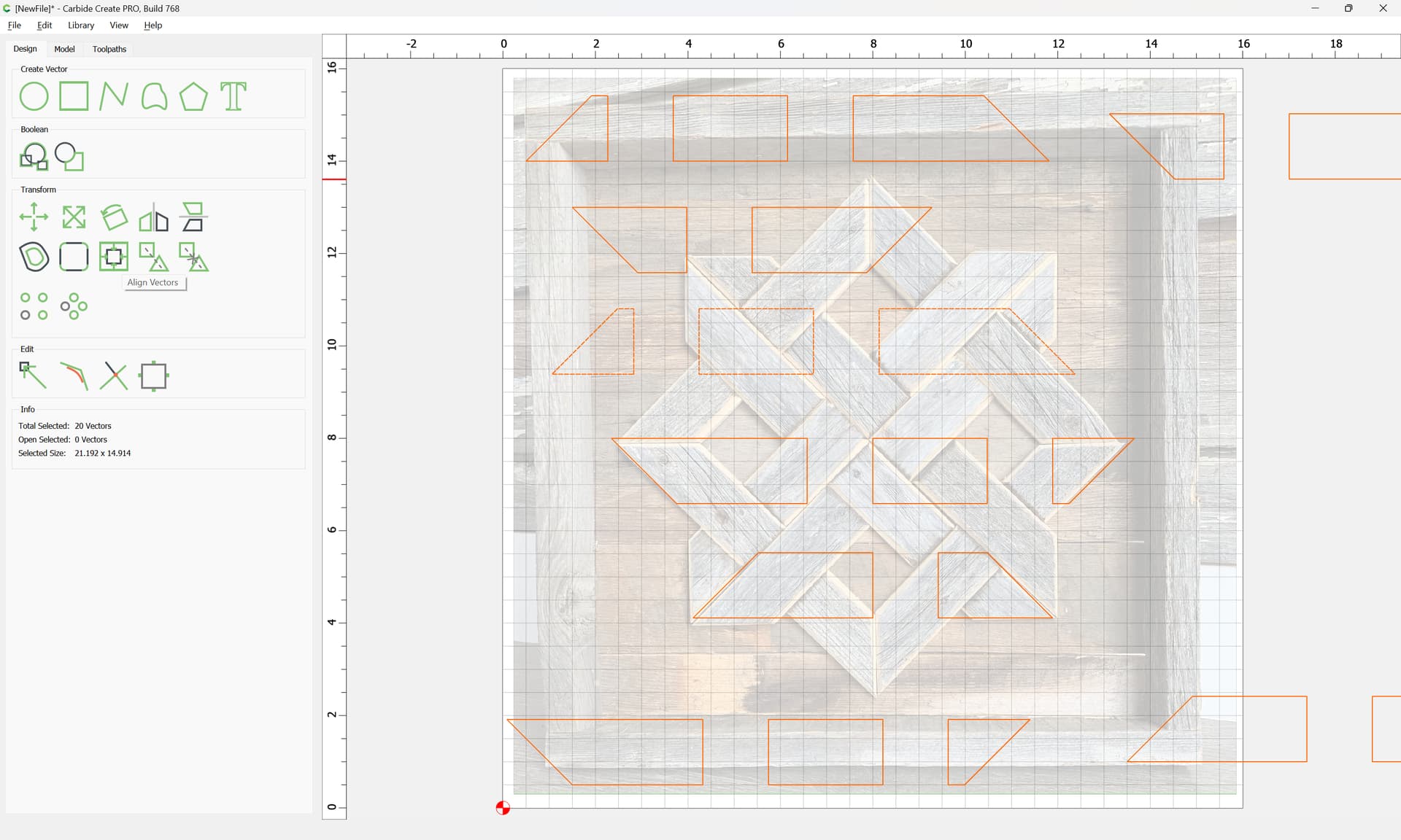
It is then a matter of selecting the geometry which represents each length of board:
Grouping it:
and dragging it out of the way:
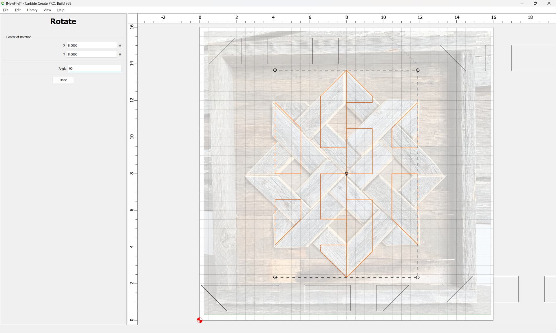
Selecting the remaining geometry:
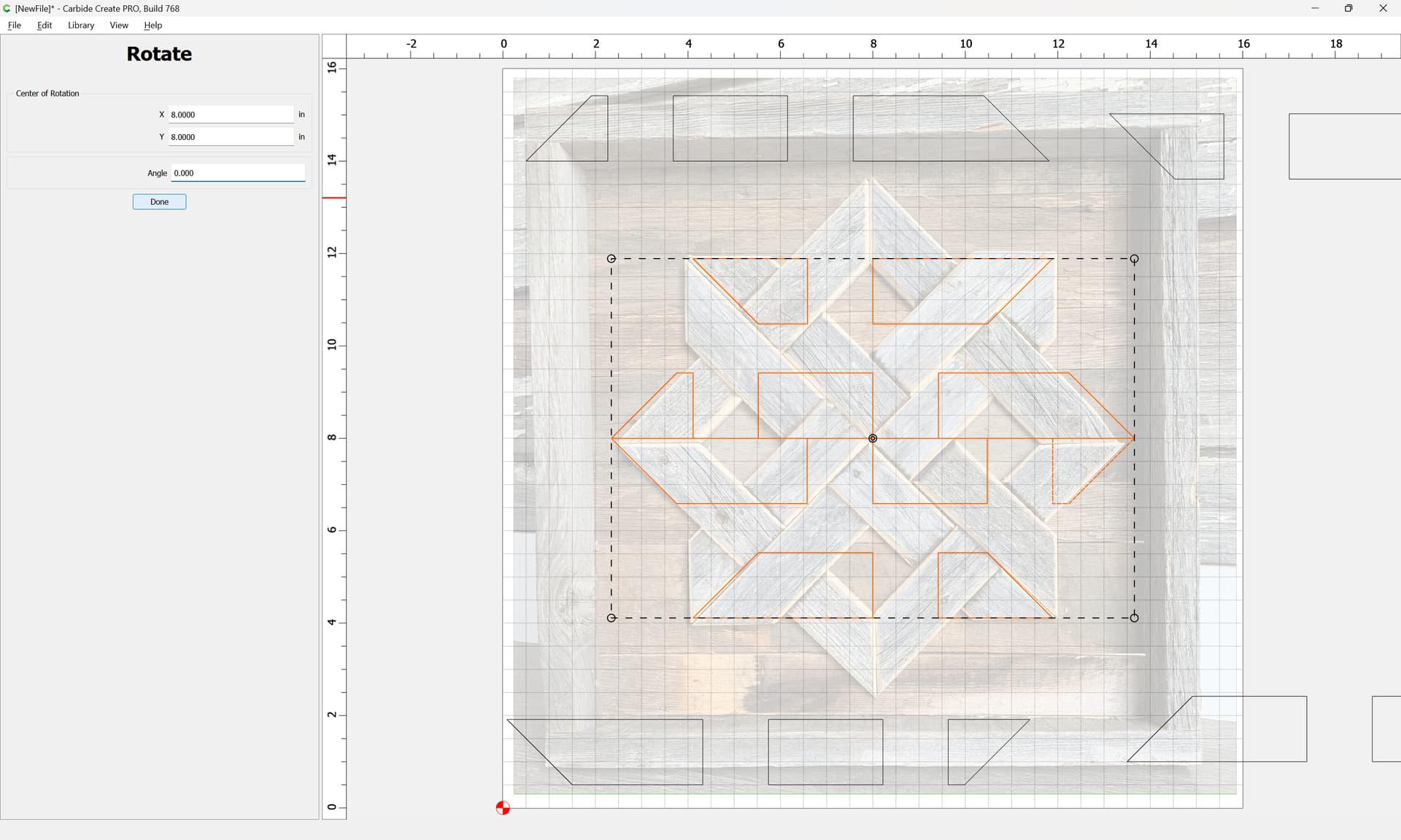
Rotating it 90 degrees:
Done
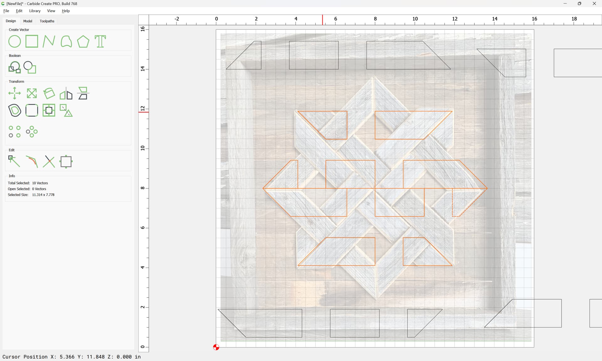
and repeating:
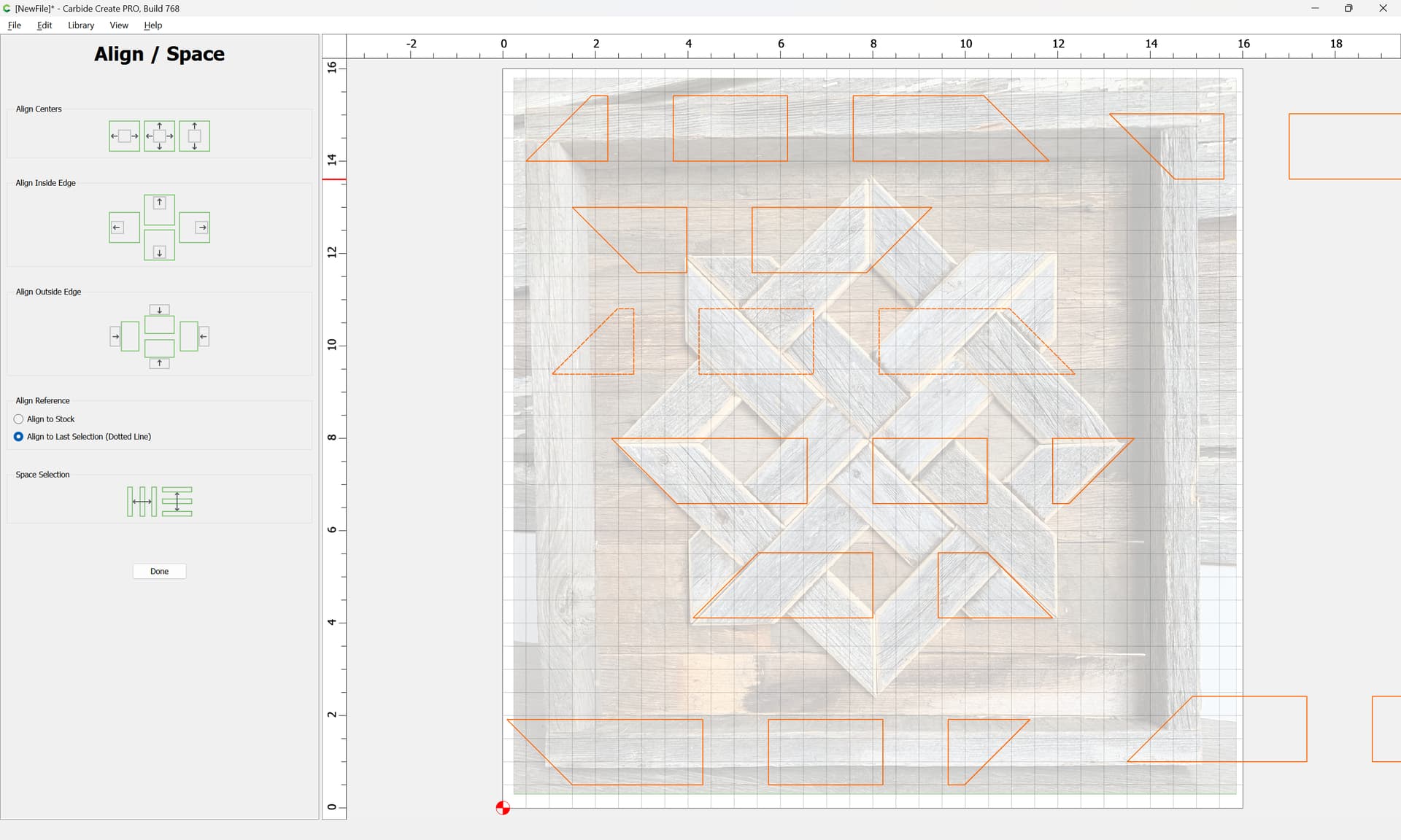
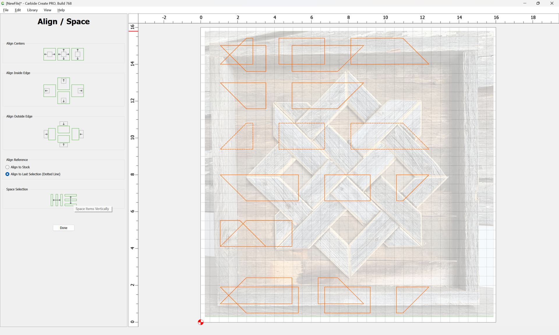
At this point the geometry may be left-aligned:
and distributed vertically:
at which point the background may be hidden:
Done
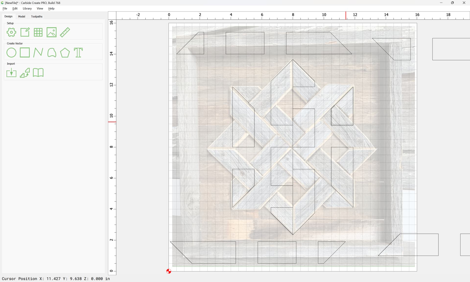
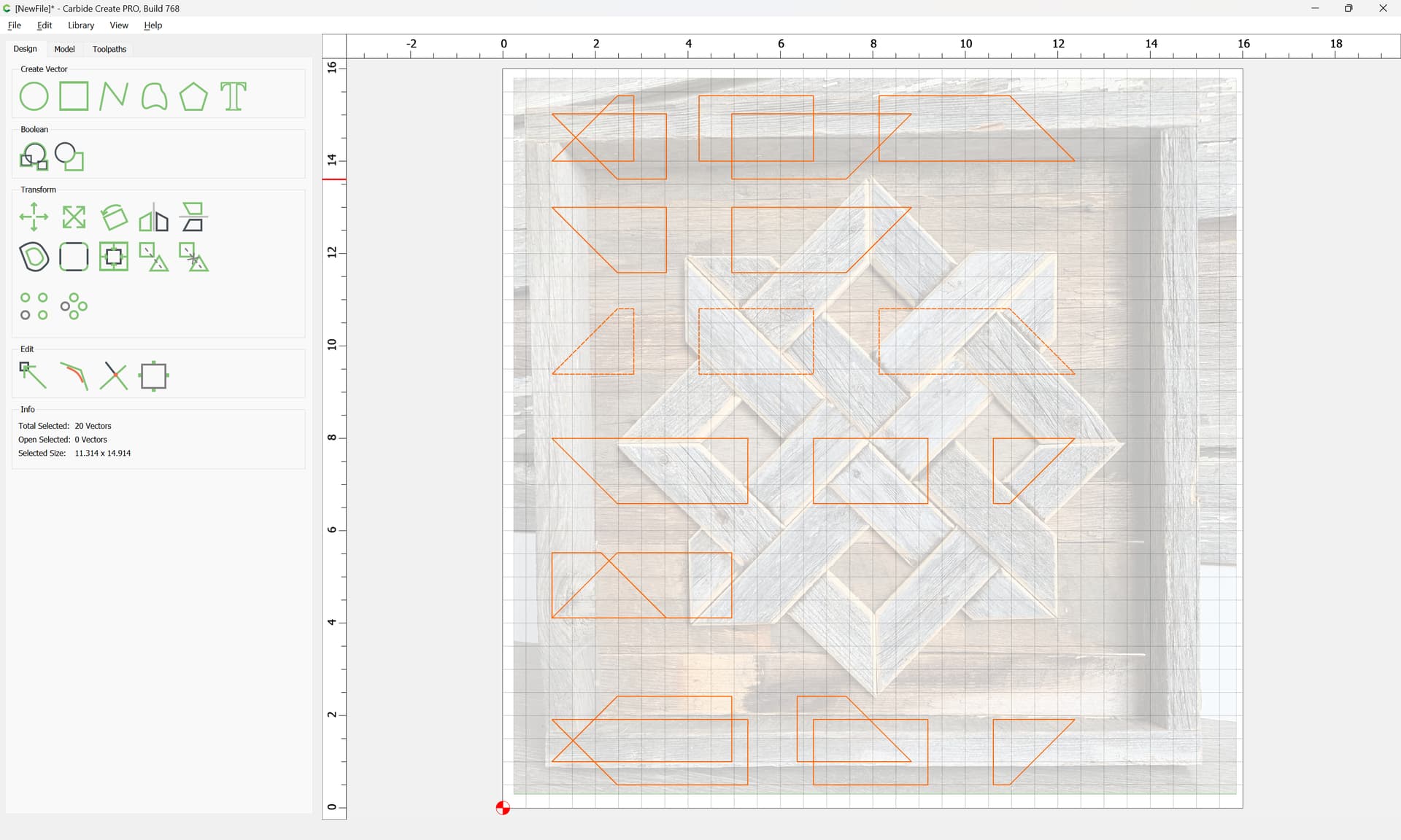
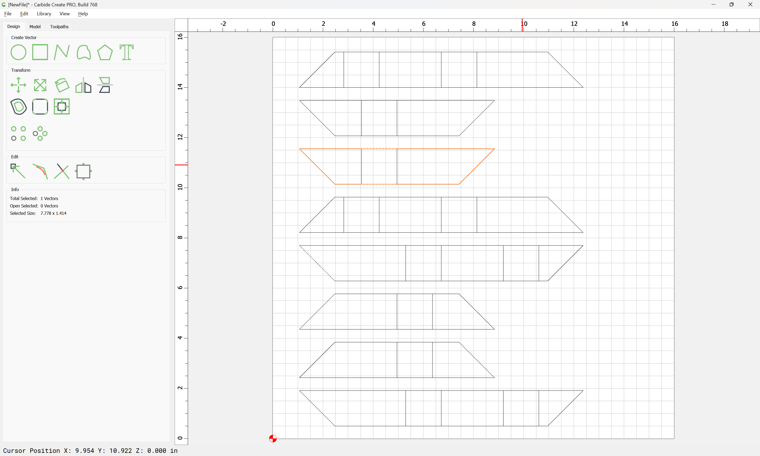
Then use the polyline tool to draw in the outline of all the boards:
Repeating until one arrives at:
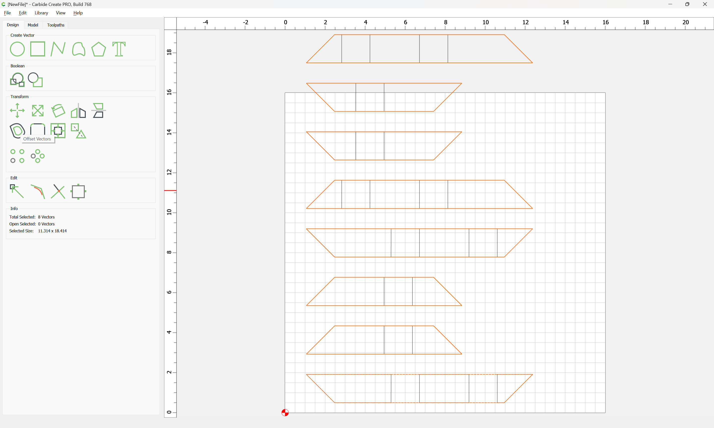
Space things out a bit:
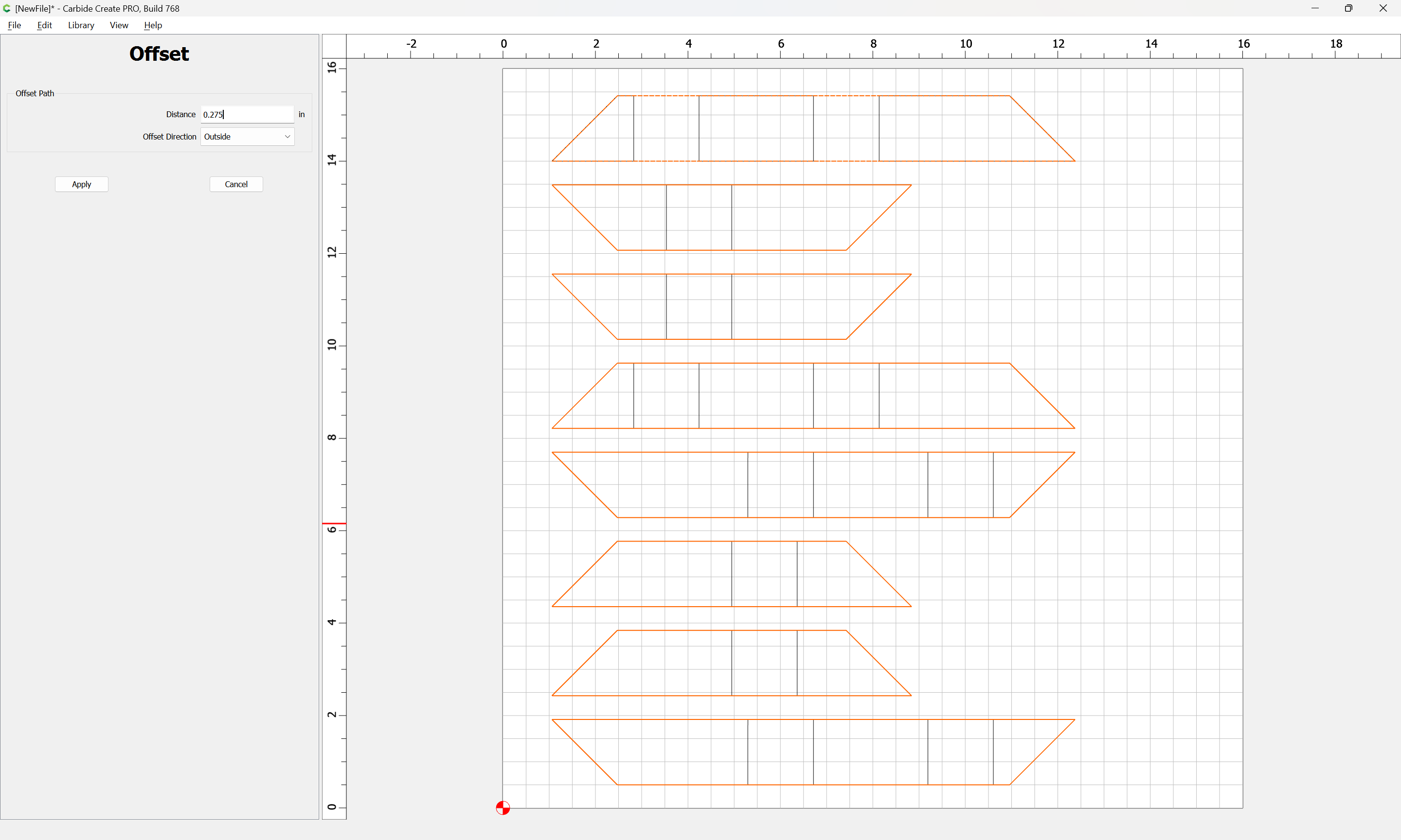
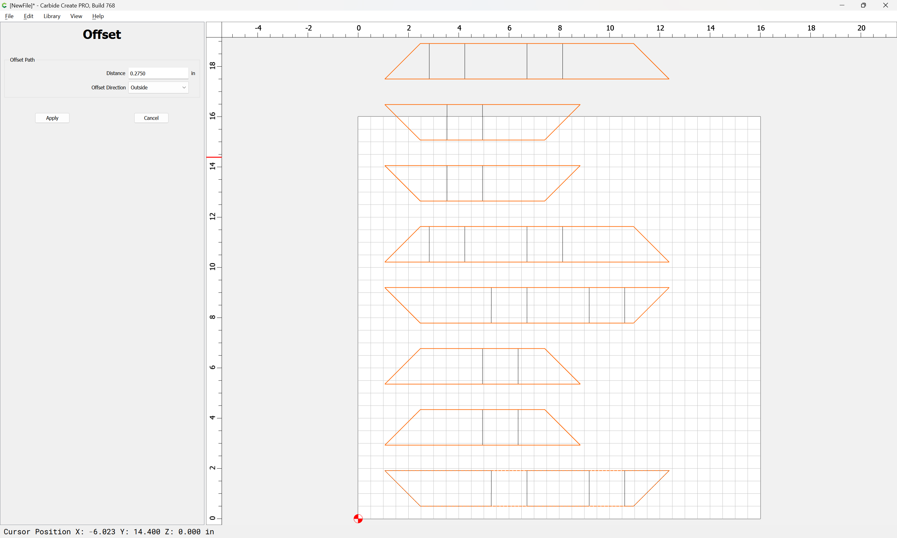
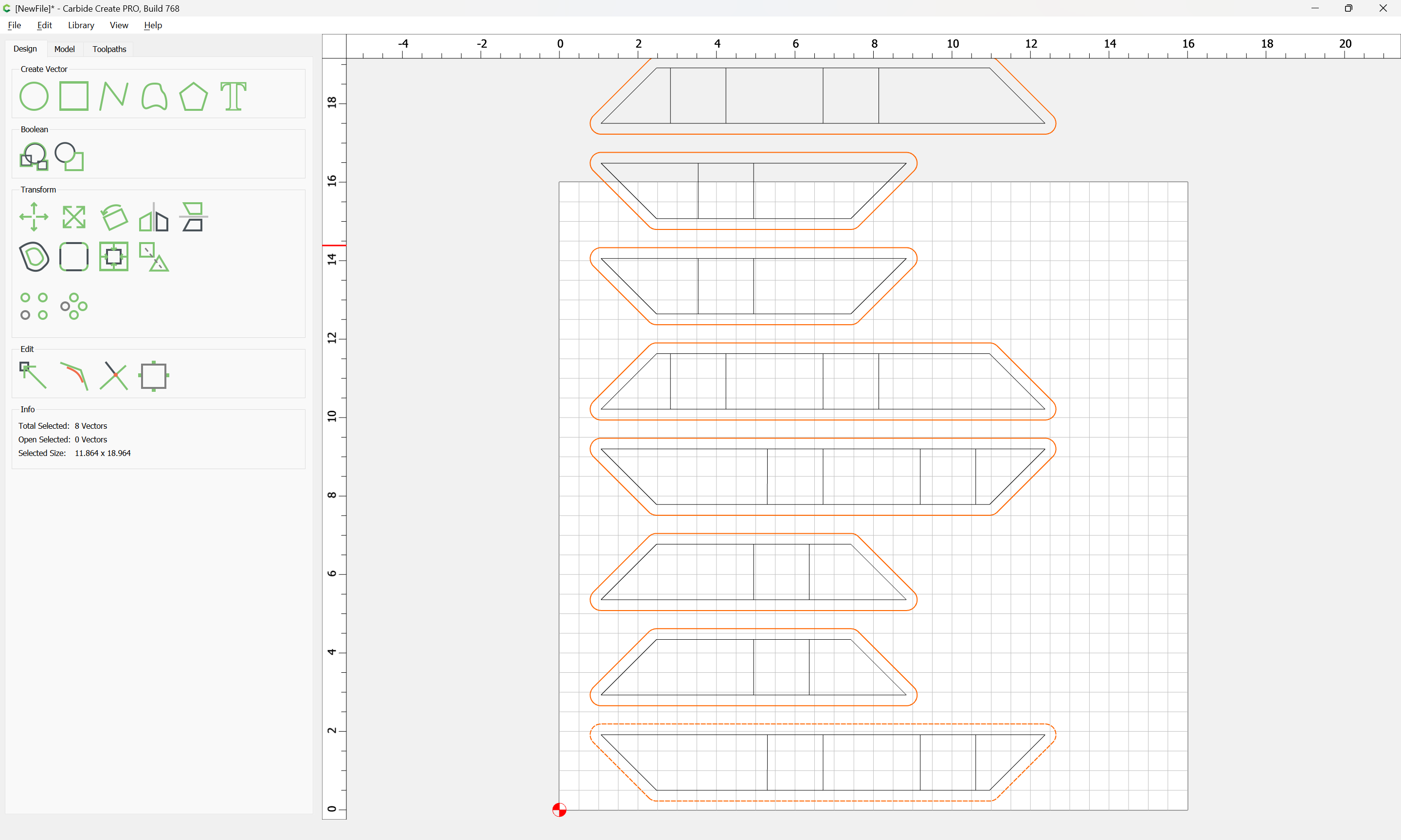
Select all of the board outlines:
and offset by tool geometry plus 10%:
Distance: 0.275in (assuming a 1/4" tool)
Then assign toolpaths.
1 Like
WillAdams
March 6, 2024, 11:41pm
3
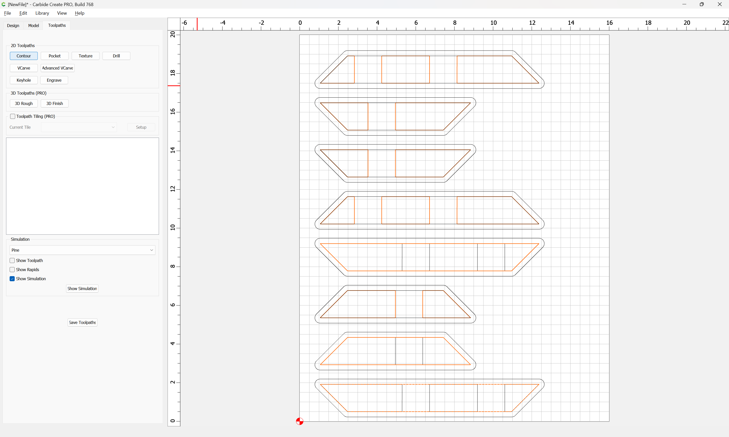
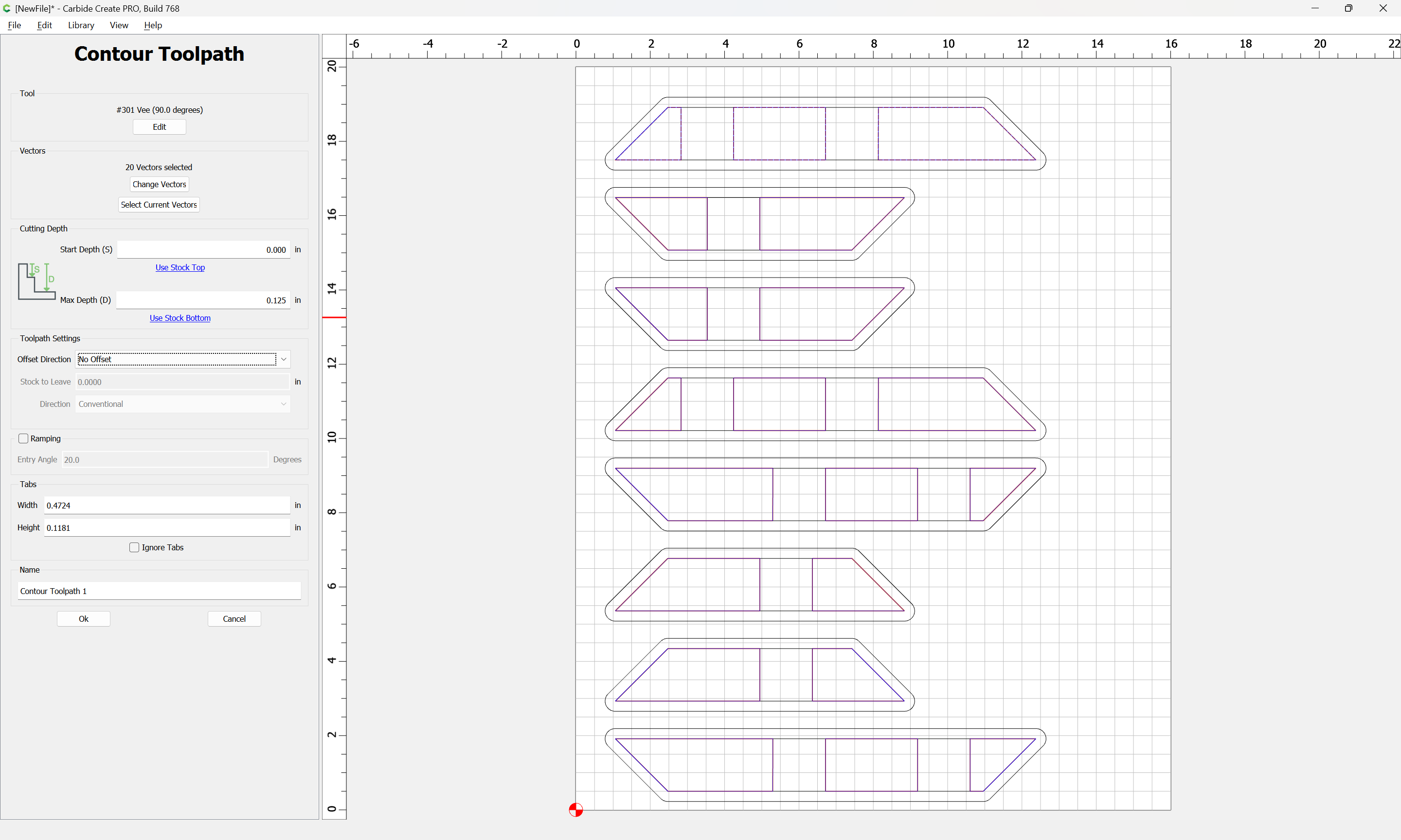
Increase the Stock size as necessary and select the original geometry:
Then assign a No Offset Contour toolpath to a suitable depth:
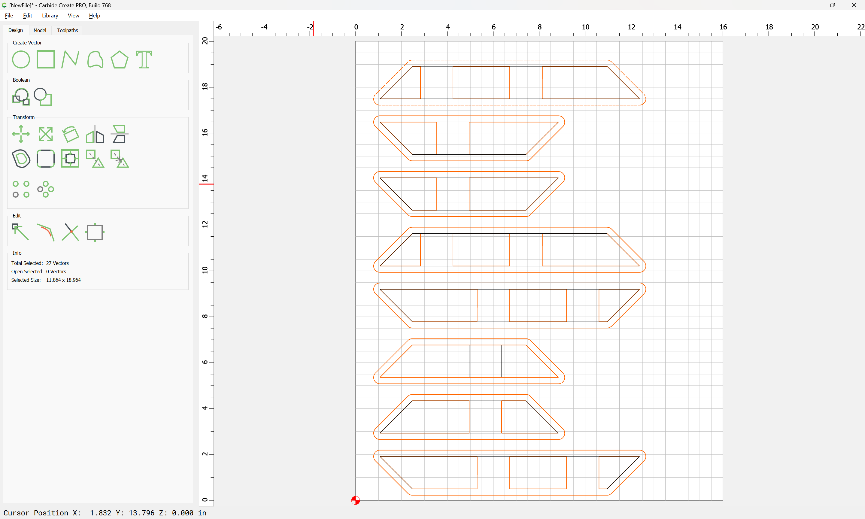
Then select the original and offset geometry:
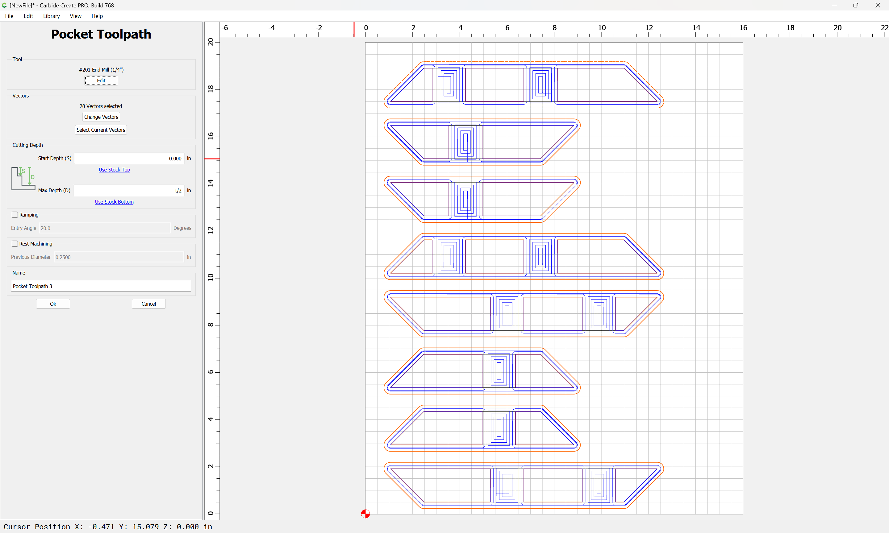
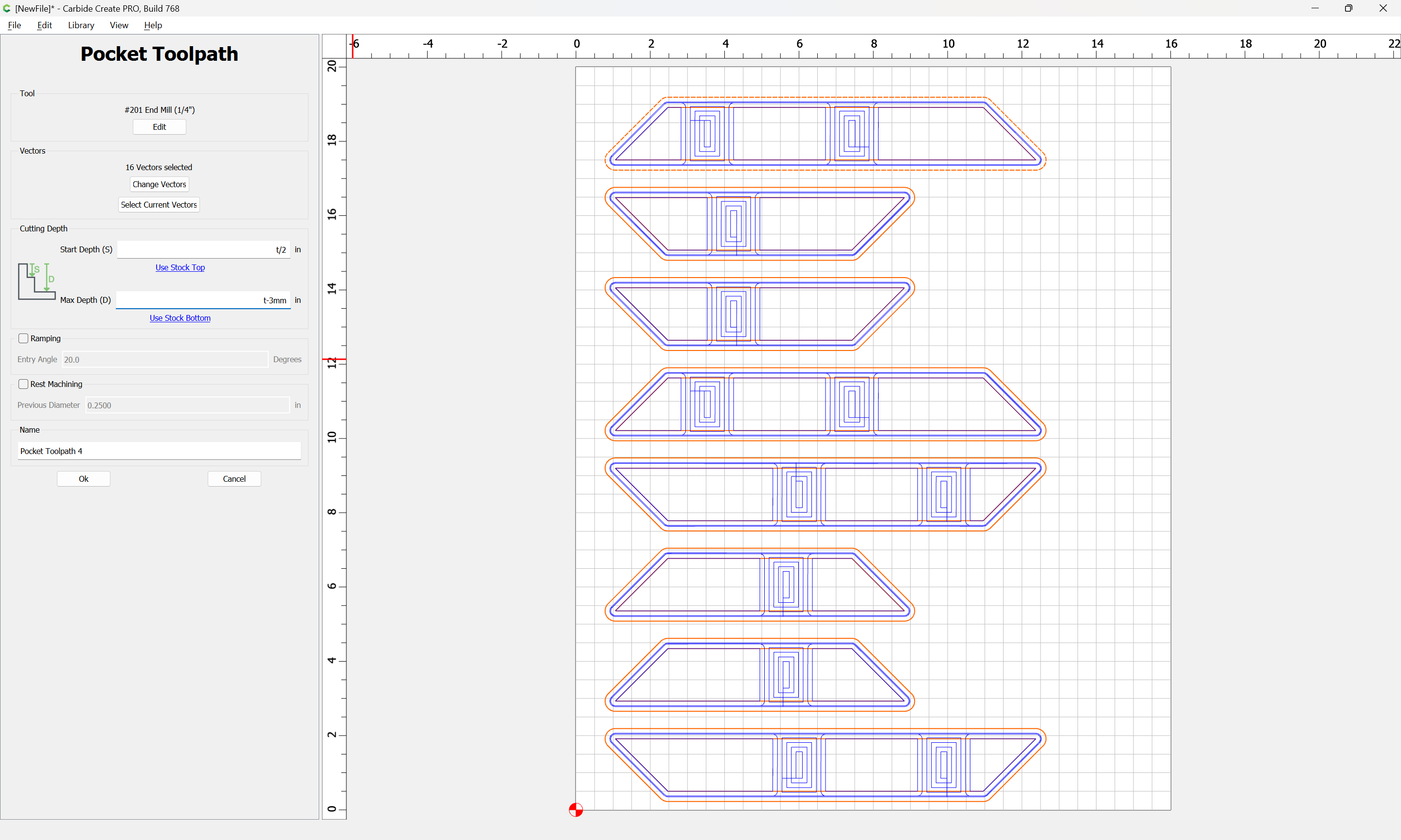
and assign a Pocket toolpath to half the stock thickness:
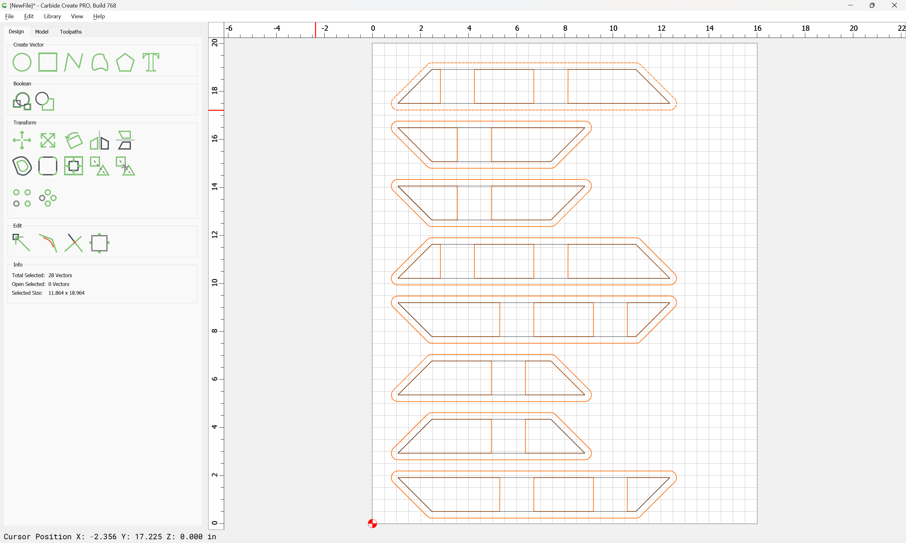
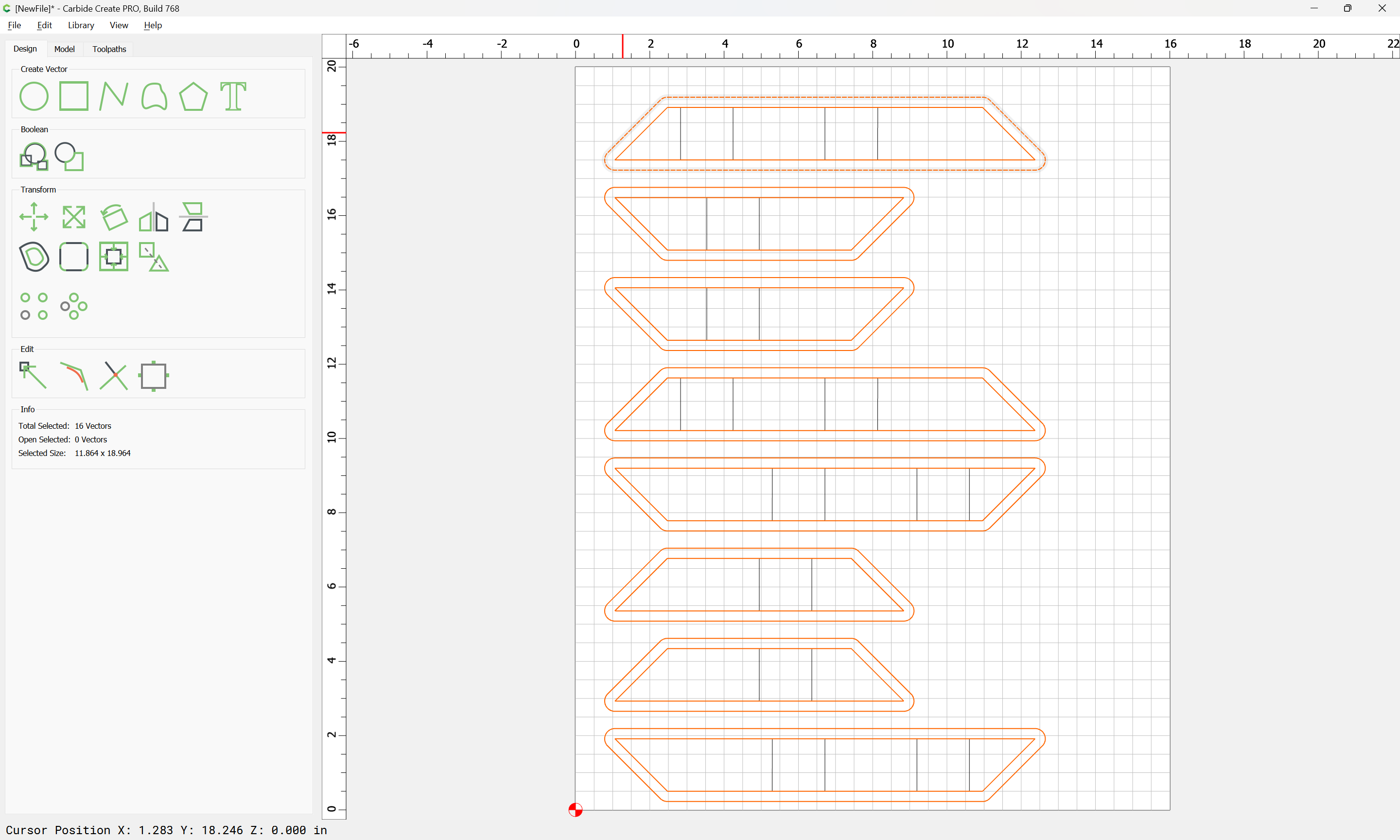
Then select the board outlines and the offset geometry:
and assign a Pocket toolpath which starts at the bottom of the previous pocket and cuts through (assuming workholding which will hold things in place) or to tab height:
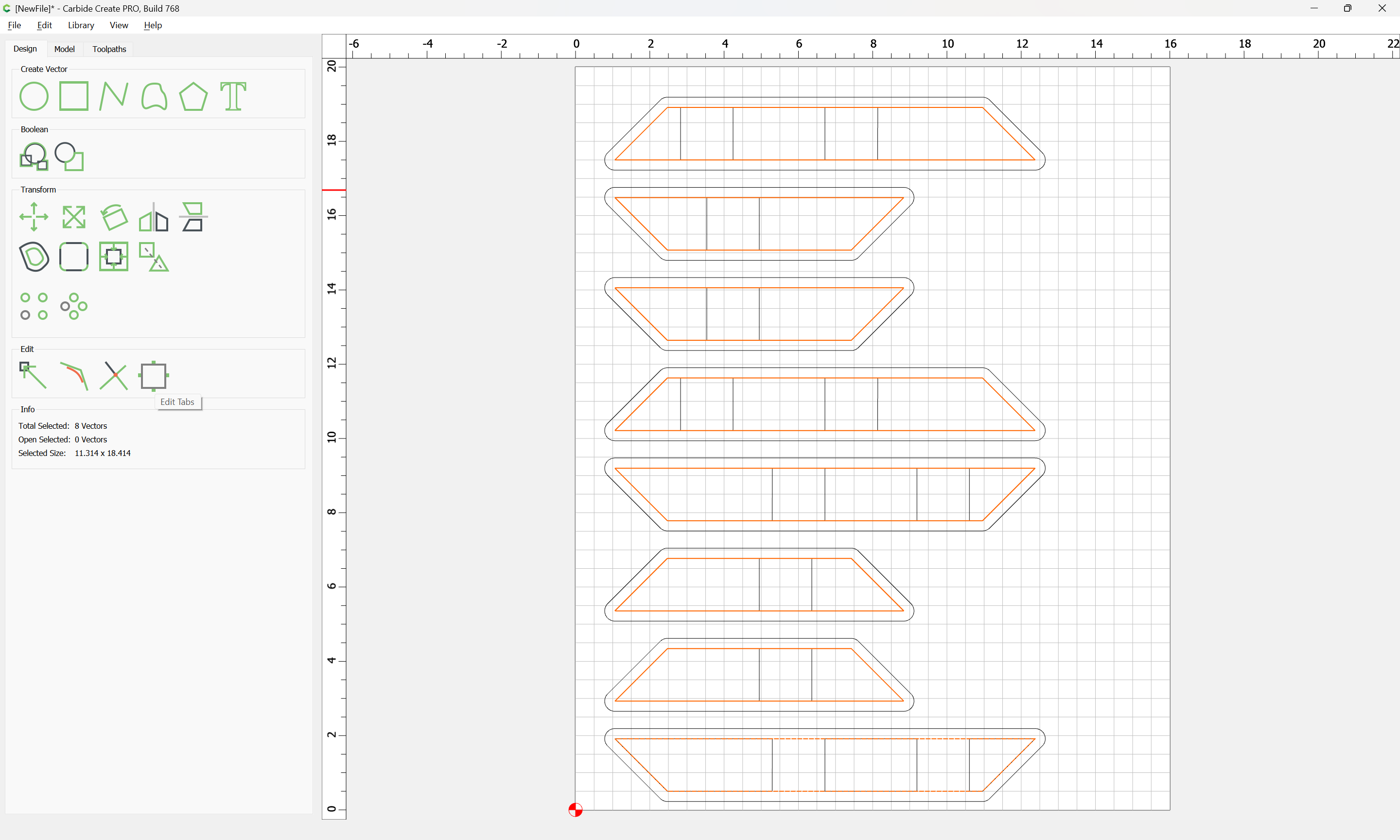
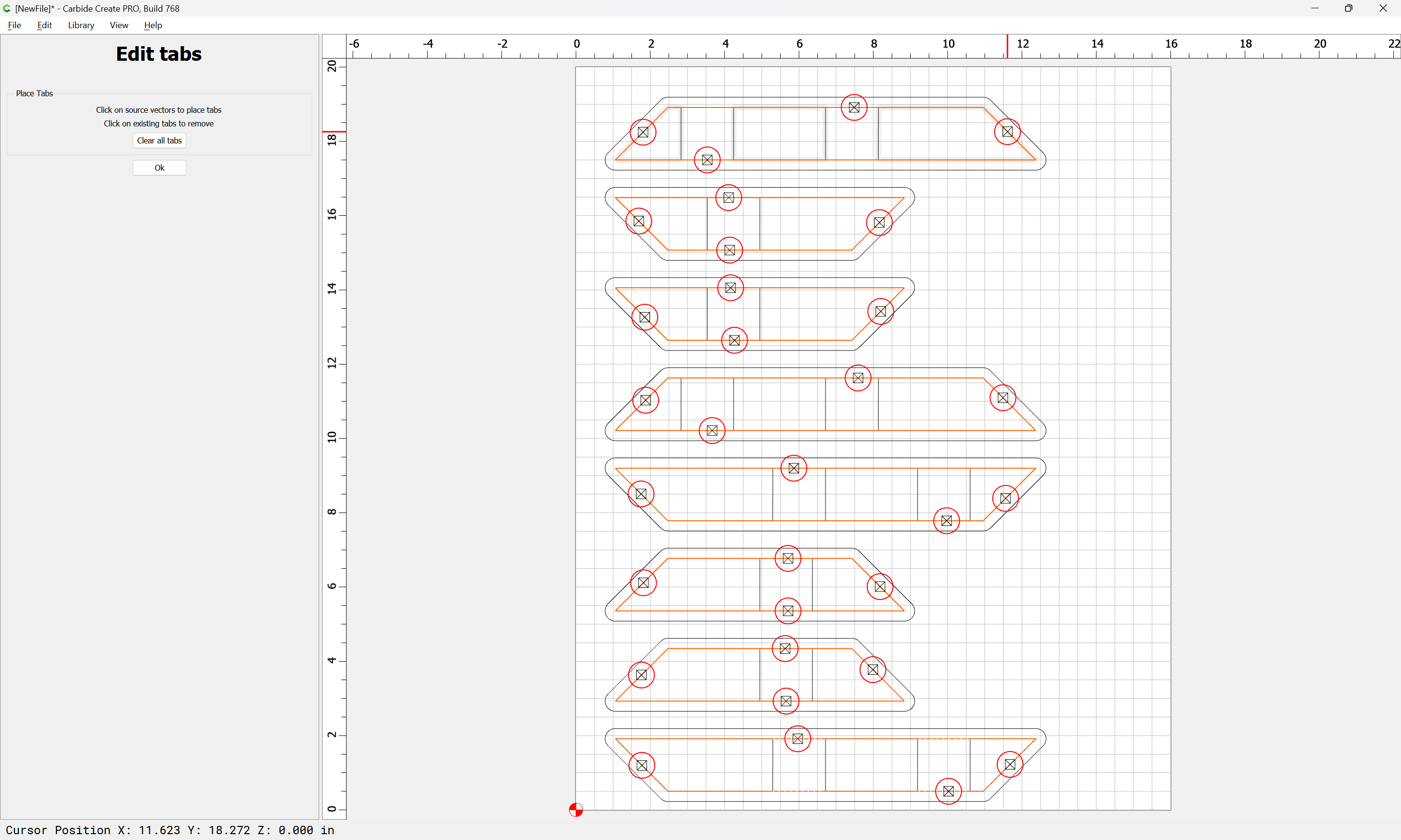
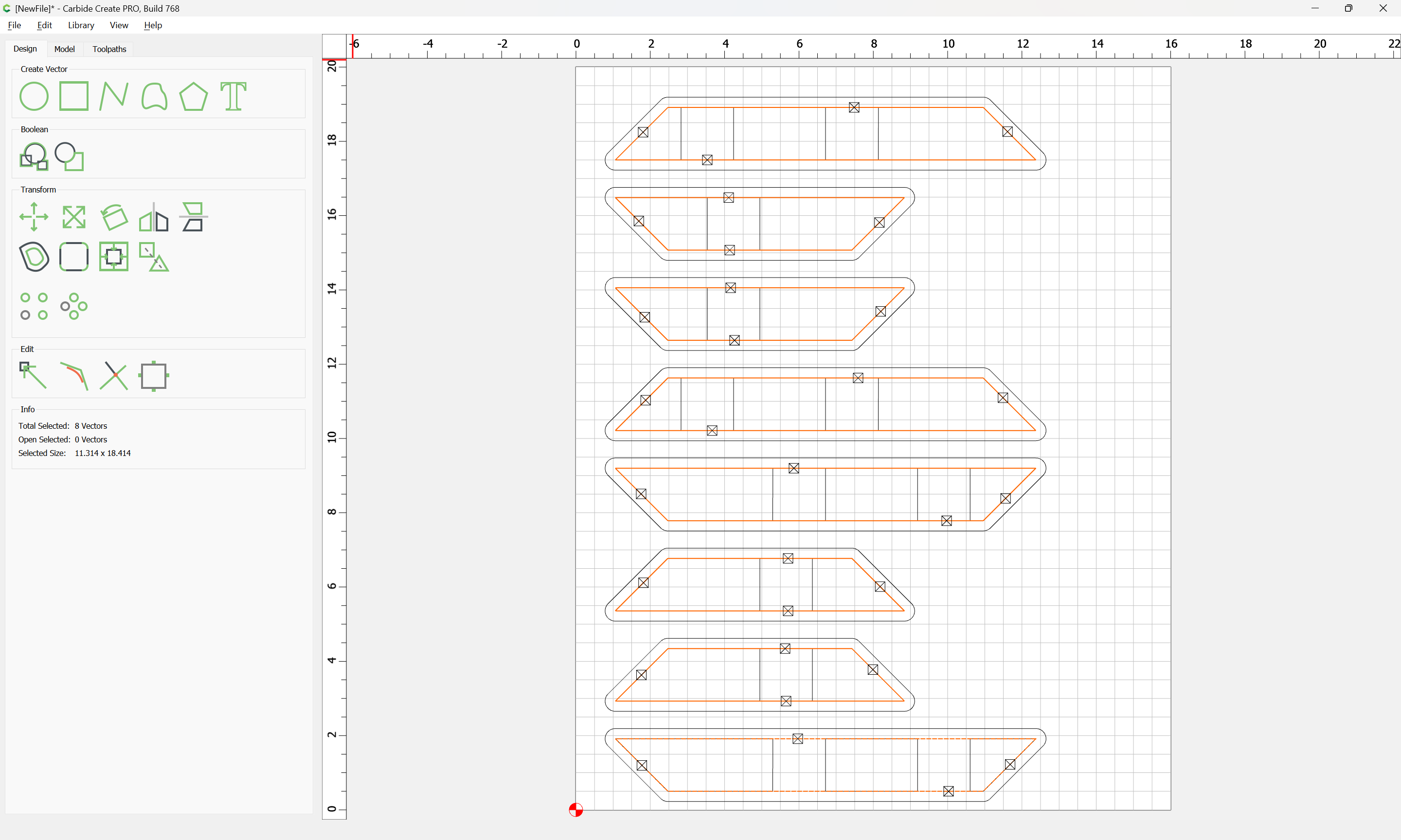
If using tabs select the part outline geometry:
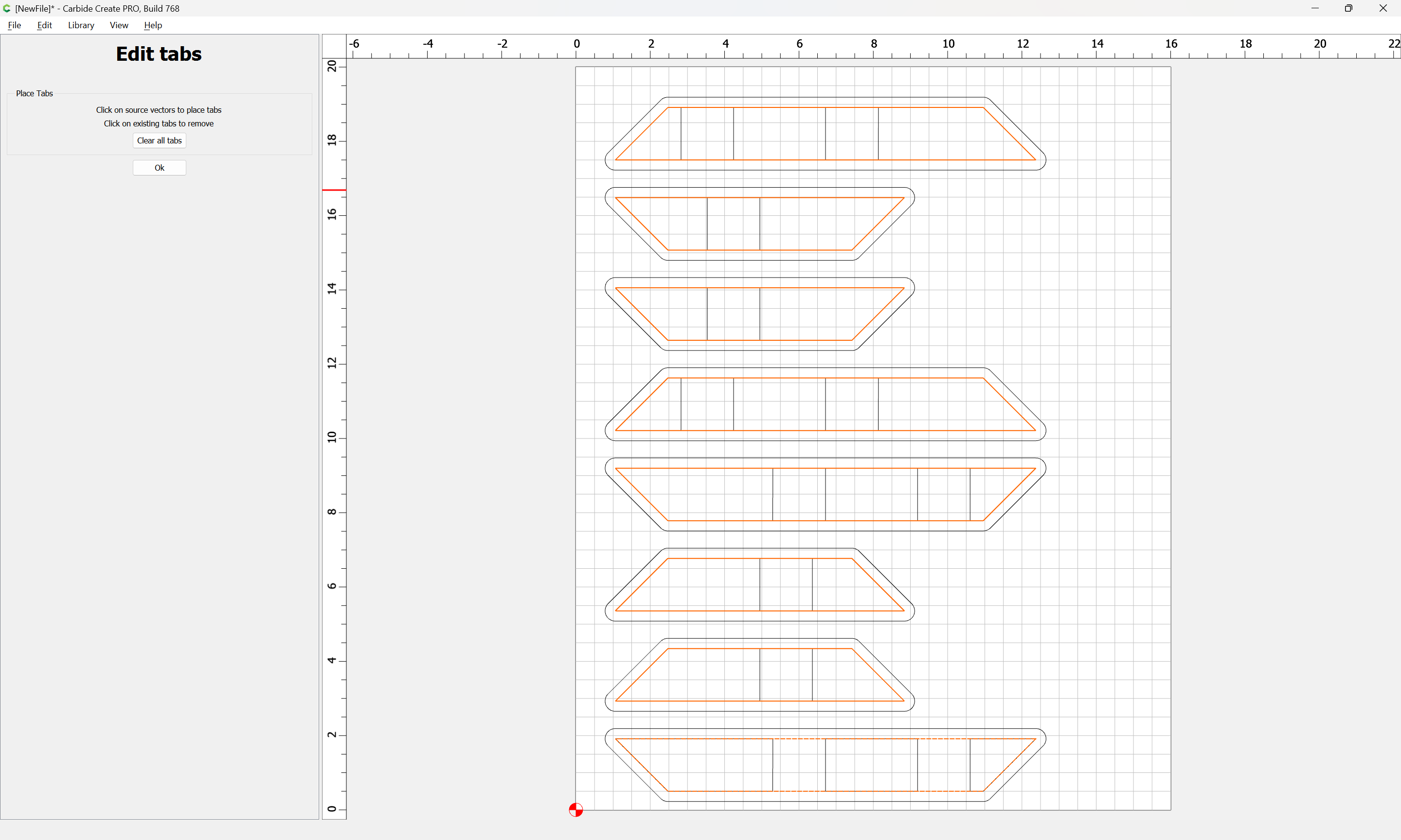
and Edit Tabs:
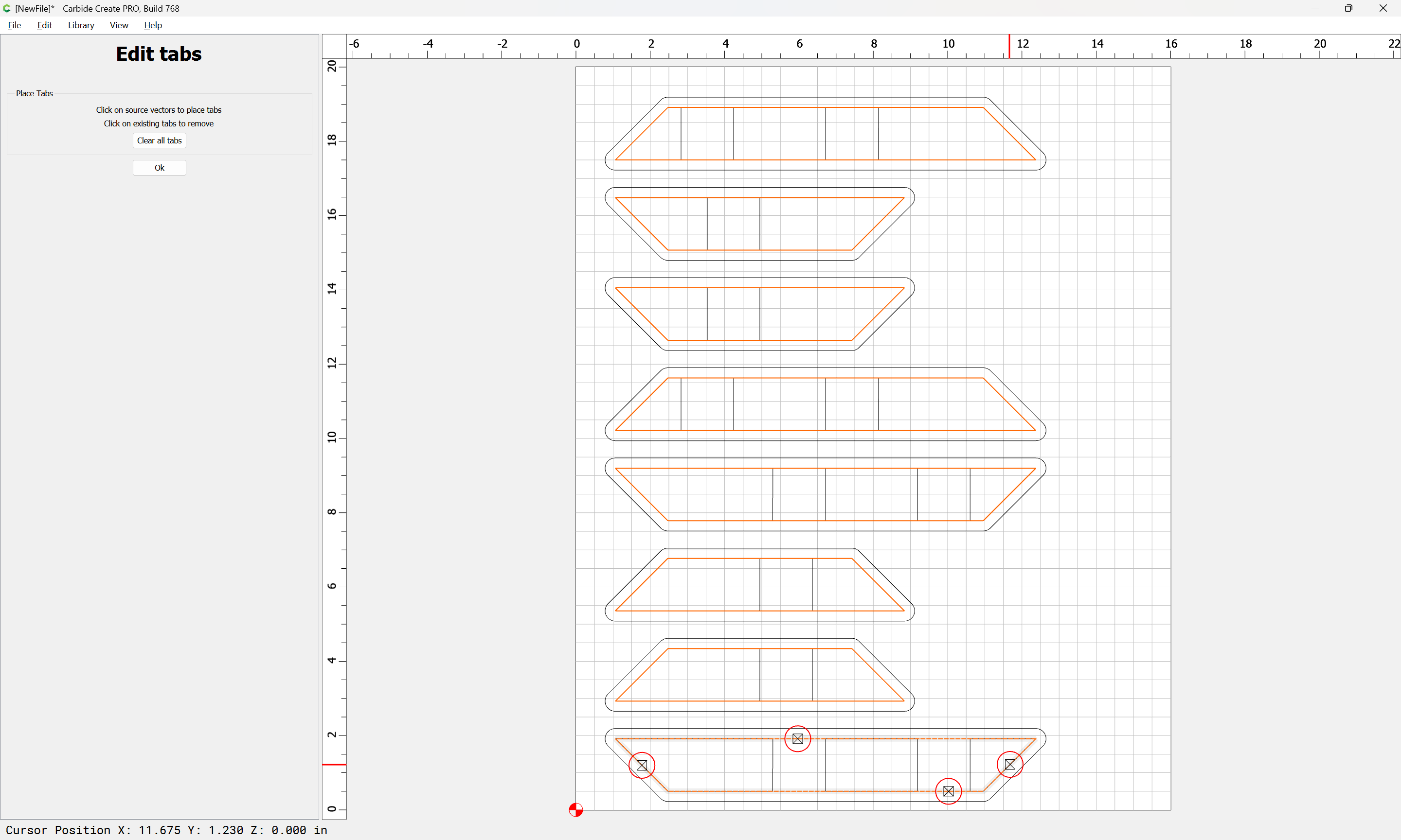
Adding as many tabs in suitably unobtrusive places as is necessary to hold things:
Ok
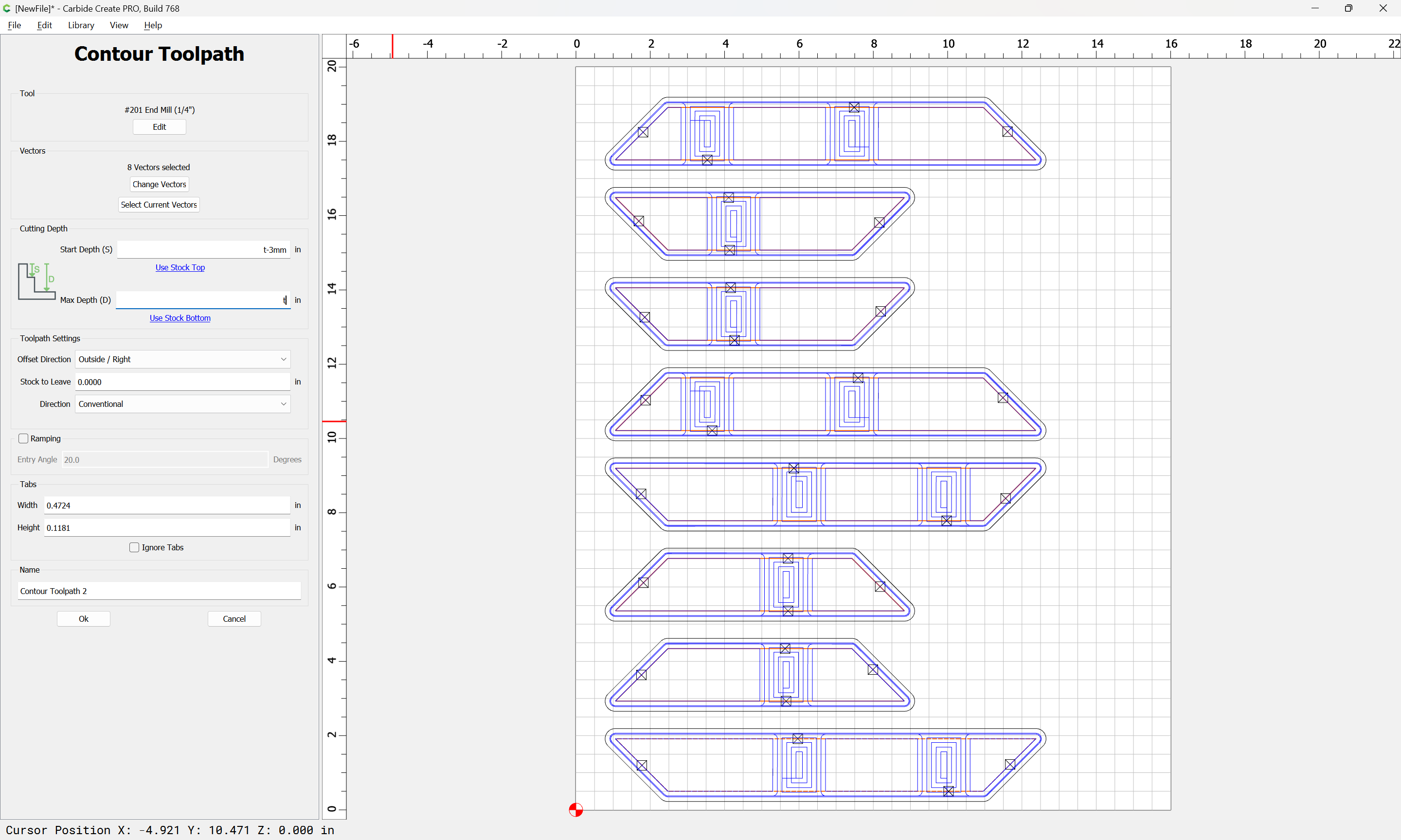
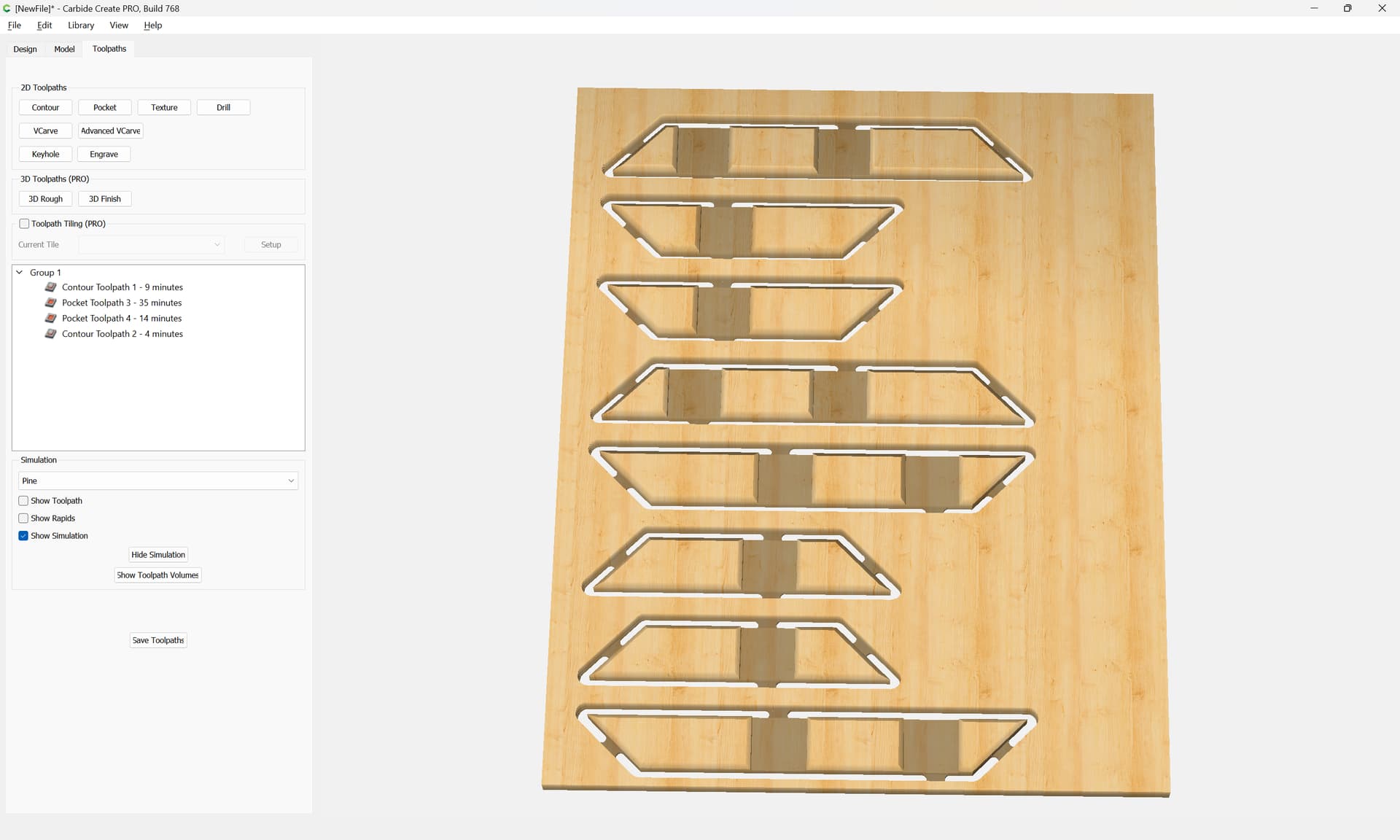
Then assign an Outside Contour toolpath which starts at tab height and cuts through:
which all previews as:
Then the geometry may be arranged so as to be optimally cut out of the boards in question, minimizing waste.
It will then be necessary to cut matching half-laps on the bottoms of the boards — probably the easiest way to do this would be to make a fixture would allow clamping the boards upside down using the top half-lap to register things, then cutting the other half-lap adjacent to it, using an inset V perimeter pass (you’ll need a narrow V endmill) to prevent the boards from being cut apart — this is left as an exercise for the reader.
3 Likes
system
April 5, 2024, 11:41pm
4
This topic was automatically closed 30 days after the last reply. New replies are no longer allowed.