Next came the CAD model. I modeled the tool as a single solid, rather than by modelling the individual parts. In this case, it was a little easier, but it is often easier or necessary for other reasons to model the parts and assemble them in the CAD system.
First, a boundary/outline. This is for the tool with the jaws open a little, and comes in useful later when using the model to make hollows in the bottom and top.
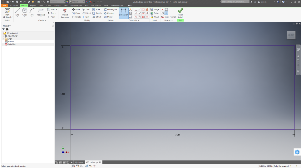
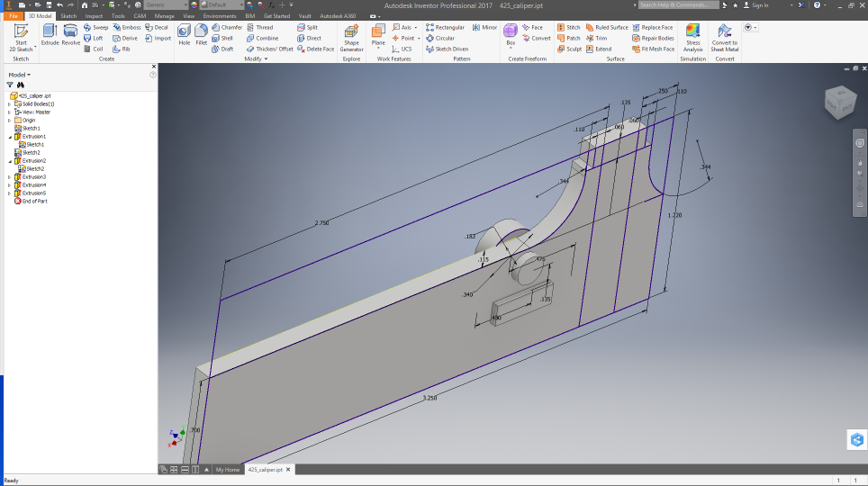
Then, the profile of the tool outline (with the jaws open a little) is drawn and extruded to a solid

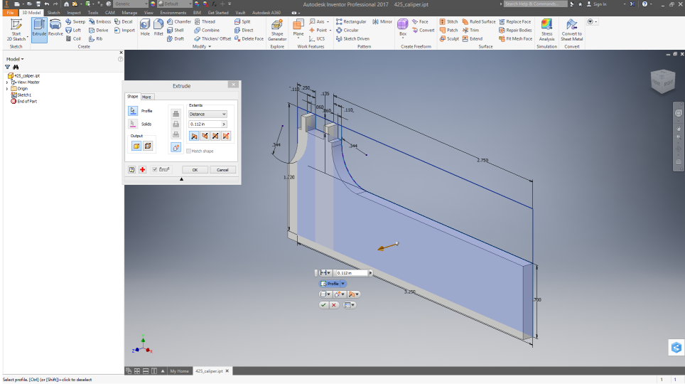
After that, other features go on: the lock knob on the front, the grip on the back, and the lock wedge/screw end on the back. This is one place I cut serious corners. These are modeled simply and with maximum dimensions, rather than to accurate form, making the lock know a cylinder and the thumb grip a rectangular block.
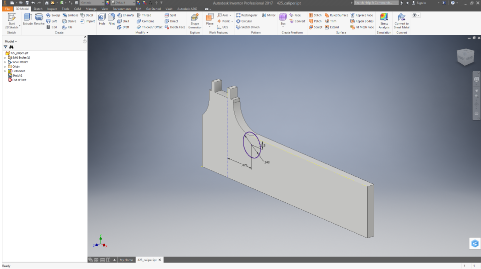
These featured are modeled by selecting the appropriate face of the part as the work plane and dimensioning from the existing features.
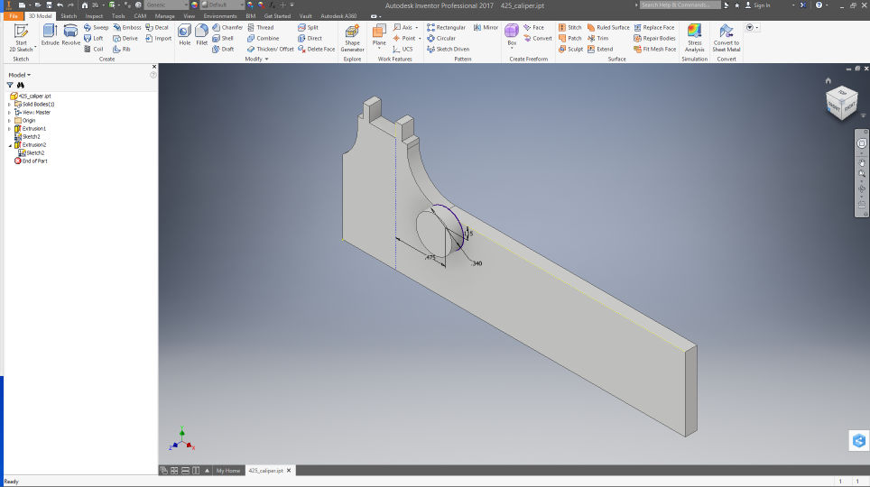
Once that was done, I stretched the features. This is another shortcut. It is better for a general purpose design to sweep the part when making the cut into the top or bottom later, but this is faster for a one off.

Next, making the box from this model