Using the tool to make the case:
I began with the bottom (the steps for the top are the same, essentially). A new part is opened and the Derive operation is used. Most CAD systems will have something similar-- changes in the original will be reflected in the derived part(s). The first derived part is a rectangular block sized from the original profile. It would have been better if I had centered it, but I was lazy.
Then I added the caliper model (again using Derive) and positioned it where I want it.

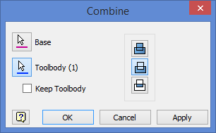
The block and the caliper are two independent solids at this point. The caliper is embedded in the block, and will be used as a ‘toolbody’ to cut the block (the ‘base’) in a Combine operation.

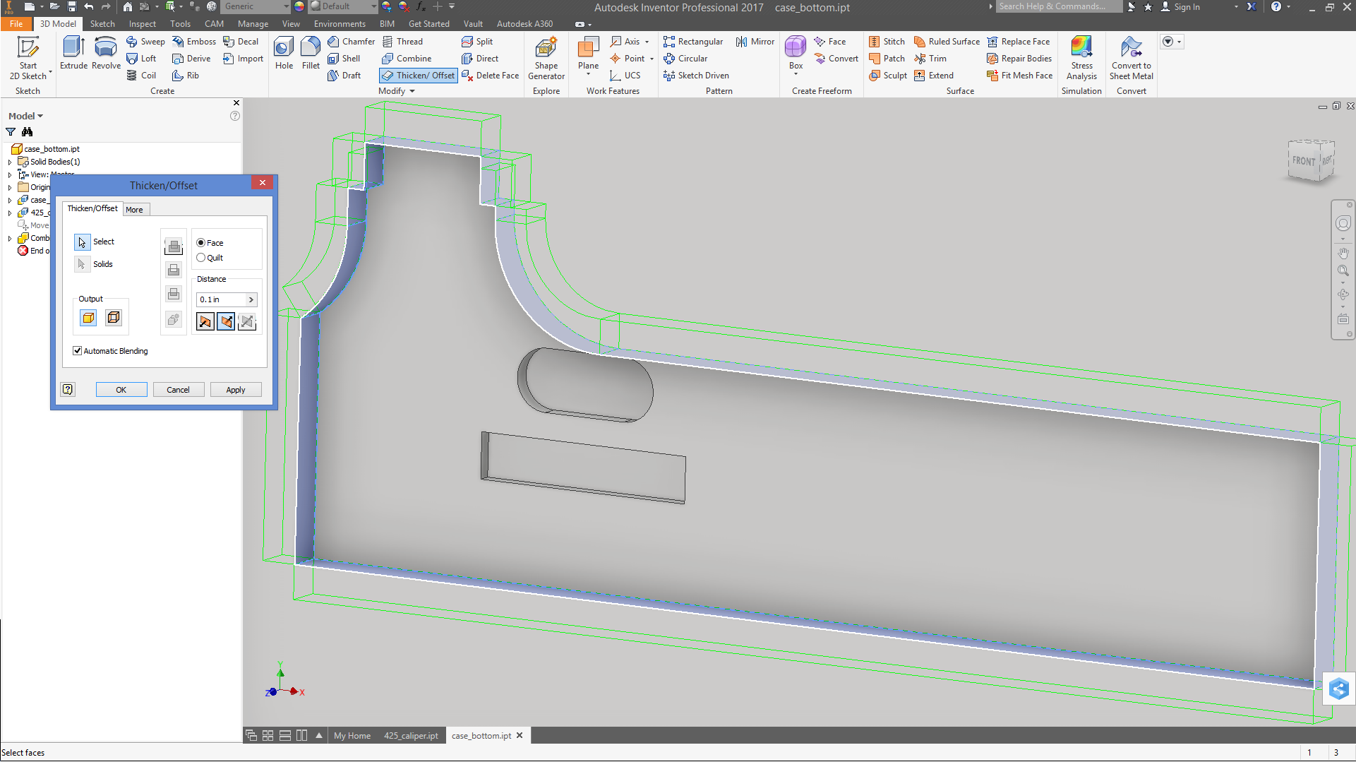
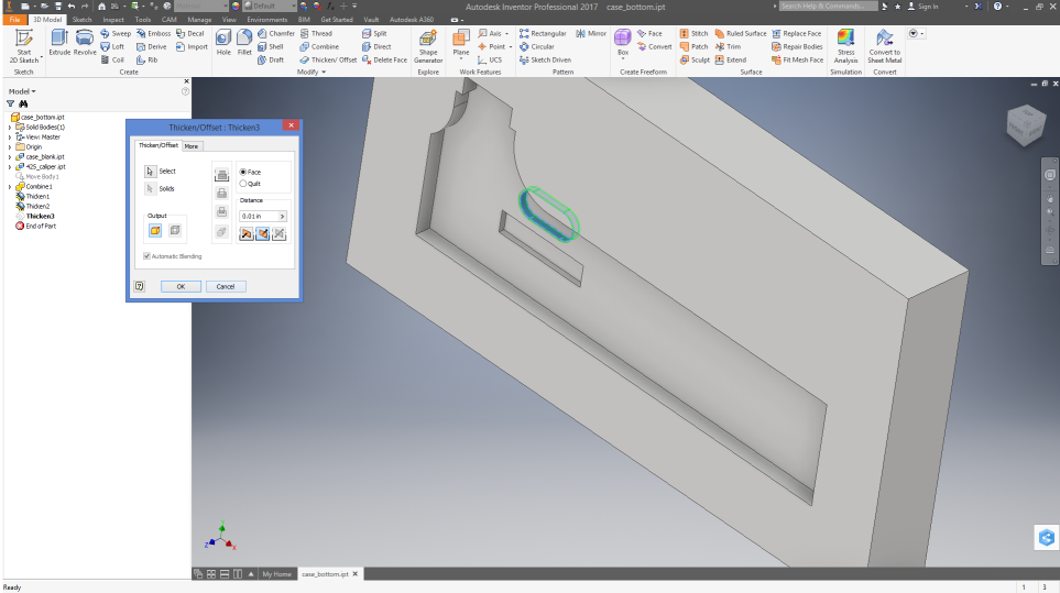
You can see the hollow for the tool (open about 1/4" with extended cuts for the thumb grip and back side of the lock), but using this to make a case would result in a the caliper not fitting. Therefore, the walls are offset by to give clearance so the caliper will fit neatly without jamming. The clearance I used is 0.01" all around (to make it visible in the screen shot, I set it to 0.1").
The top of the box was done similarly. This is usable as-is, but features for hinges and a latch are very nice.