How does everyone make a fixture be parallel with the cutting axis’s
I’ve done it with two passes…the first job cuts holes that I use to screw the fixture into the myers spoilboard. Then I attach the fixture to the spoilboard through those holes - and run the job that cuts the line. This way, I’m certain the fixture is perfectly parallel to the axis of the gantries.
1 Like
The most accurate way is to let the machine cut it.
So for example, cut out a rough “L” piece of 1/4" (6mm) MDF or similar. I use an “L” that is 6" (Y) by 15" (X). The use your favorite CAD software to run the cutting bit down the inside of the “L”. Hope that makes sense. Or you could use a large square of material and cut the “L” out of it.
Make sure you cut a relief in at the corner of the L to allow material to sit flush…
I’ll grab a picture of mine, or perhaps someone will beat me to it 
This way the inside of the “L” will be be 100% parallel to both axis.
2 Likes
that is what i was thinking, but what if the fixture is steel or a vise
I guess I wouldn’t ever be making a fixture out of something the machine couldn’t cut - or I’d always be worrying that the bit would wander onto the fixture and destroy itself somewhere down the line.
EDIT: I’ve made all of my fixtures out of wood or wood byproducts…I’ve even gone so far as to use 1/4-20 nylon bolts to hold my clamps. Always protecting against an accidental contact with a fixture
If you have a vice, maybe design a perfect set of holes to attach the vice…take that design and put it onto a design that perfectly matches your spoilboard hole pattern (not the same holes). Then do the two step process again: Machine the spoilboard holes into a thin piece of wood, attach the wood to the spoilboard through those holes, then run the job that cuts the vice holes (parallel to the axis) into the wood, and then attach the clamp to those holes?
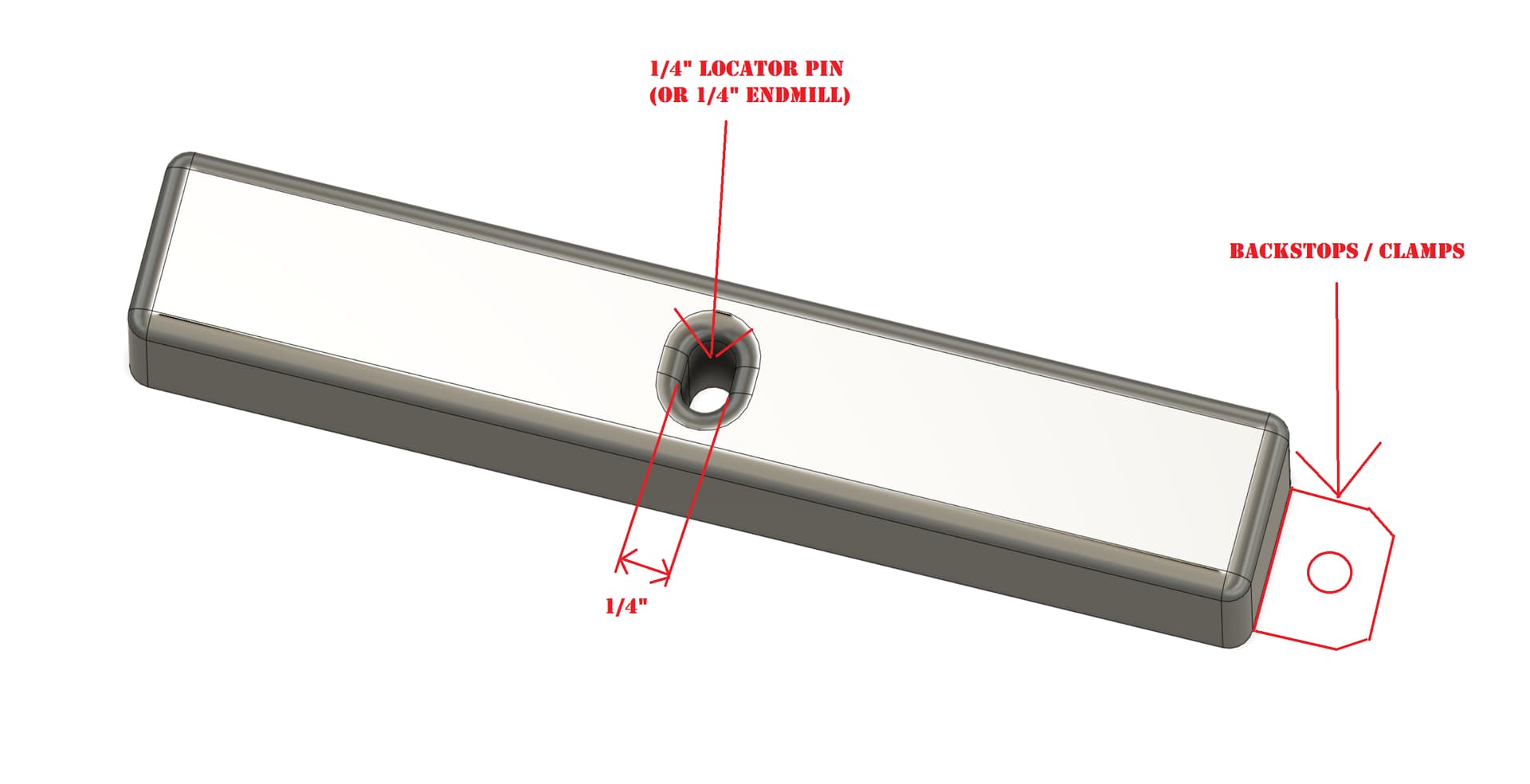
Not sure what machine you have but I have a Shapeoko Pro with the hybrid table so made myself a little jig which just fits in between the MDF slats sitting on the aluminum extrusion for the T-track system and use the 1/4" locator pin in the collet and jog the router on the X axis only to precisely position my backstops. Here’s a sketch of what my jig looks like.
Steps:
1 - Jog to a certain Y position close to where I want to secure my back stops/clamps that will become my reference that is perfectly parallel to my X-axis gantry.
2 - Jog on the X axis to line up the 1/4" locator pin with the t-slot to secure your first backstop/clamp
3 - Lower the Z-axis until the locator pin descends into the hole in the jig locking it into position
4 - Position your backstop/clamp up against the end of the jig and bolt it into place
5 - Now you need to jog on the X-axis only as so long as you do not make any movements in the Y-axis direction you’ll be able to get a reference line perfectly parallel with your X-axis gantry.
6 - Repeat 2, 3 and 4 lining up the 1/4" locator pin with other T-track slots and secure 2 or more of the backstops/clamps using this technique
7 - Once you have a row of backstops/clamps lined up using the machine you could then also make use of another clamp on the left or right as a stop block or align a square of some kind or vise by resting it against the backstops/clamps you just setup…
I prefer using this approach then just depending on the front edge of my table because if ever your frame is a bit out of square itself you may be a little off. I think using the machine itself in this way to set your backtops/clamps will likely provide your best parallel to the X axis gantry.
I use the locator pin because it’s a full circle and doesn’t have void space (flutes) giving the best snug fit in the slot in the jig. I also made wider in the one direction so it’s easier to line up and drop the locator pin into the slot.
@Griff also has a good way as there’s more than 1 road to Rome which I think he’s going to reply with shortly as I see his avatar appearing with the replying…
1 Like
Assuming we’re speaking of a machinists vise that typically have slots in the sides or some other means of attachment to a fixture plate/spoil board I’d suggest using index pins to locate the vise.
1/4” or 6mm steel or nylon pins can be sourced from McMaster-Carr. I routinely mill index pin holes on 80mm centers in my spoil boards following their attachment to the machine base. This ensures the holes are perfectly aligned to the XY.
Guessing that you do not have pre drilled index pins in your spoil board, pick a location for the vise and have the machine bore two holes in X and two in Y, forming an “L”. Snug the vise up against the pins and bolt it down with your choice of work holding methods.
1 Like
You could loosely secure your jig. Then jog the bit to the edge. Then jog in the direction you want to square and see where bit is. Adjust your fixture and lightly tighten. Reverse your direction to make sure your bit is still parallel. Sometimes during tightening you can move your jig. If you are happy that you are square with the bit tighten down and double check one more time the jig did not move during tightening.
6 Likes
Another approach in a similar direction is to cut a 2mm pocket out of something cuttable that is fixed to the machine bed, and use that pocket to align your item (vice or fence)
I take a different approach where I’ve cut a triangle and square in my spoilboard with a v-bit about .040" deep then marked the groove with a sharpie. I clamp my work piece or stop along a line that suits the project.
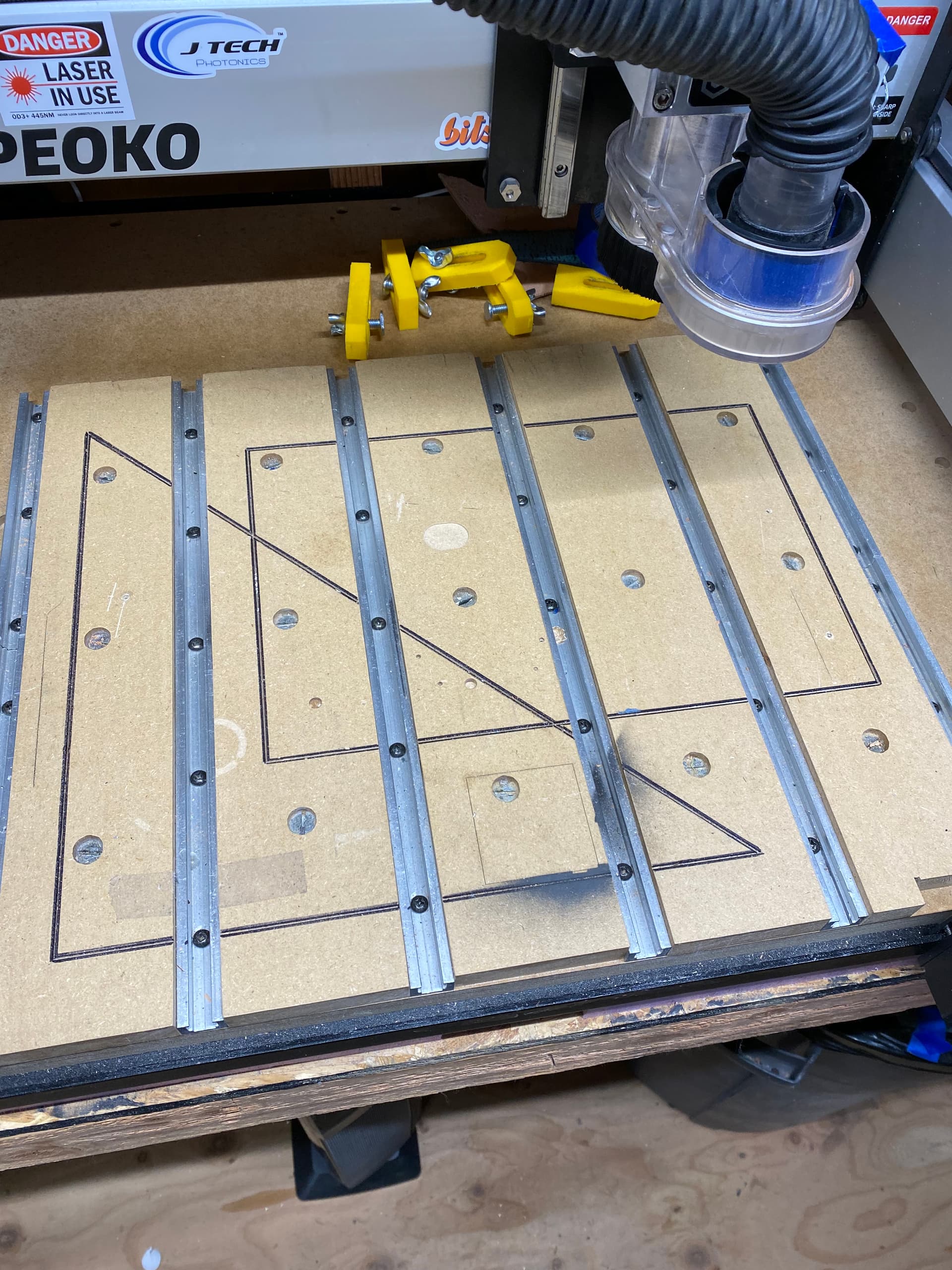
3 Likes
This topic was automatically closed 30 days after the last reply. New replies are no longer allowed.