WillAdams
May 1, 2022, 4:53pm
1
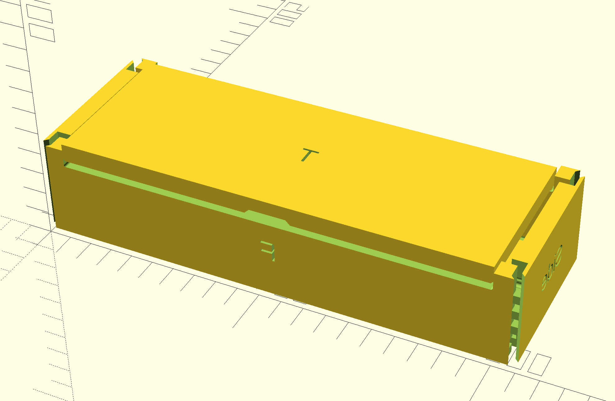
To see a 3D preview of the box w/o installing OpenSCAD see:
https://www.blockscad3d.com/community/projects/1380449
Start by downloading the OpenSCAD file:
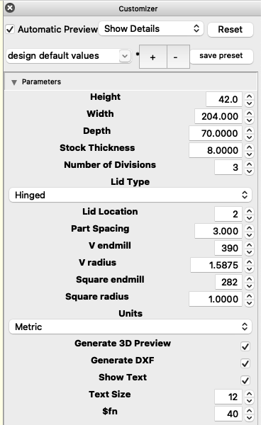
//!OpenSCAD

Height = 1.75;
Width = 8.125;
Depth = 4.0625;
Stock_Thickness = 0.3287;
Number_of_Divisions = 3;
Lid_Type = "Hinged"; // [Sawn:Sawn, Sliding:Sliding, Hinged:Hinged]
Lid_Location = 11;
Part_Spacing = 0.375;
V_endmill = 390;
V_radius = 0.0625;
Square_endmill = 282;
Square_radius = 0.0394;
Units = 25.4; // [1:Metric, 25.4:Imperial]
Generate_3D_Preview = true;
Generate_DXF = true;
Show_Text = true;
Text_Size = 1;
$fn=20;
show original
If need be, install OpenSCAD from:
Launch OpenSCAD and load the file, and set the parameters:
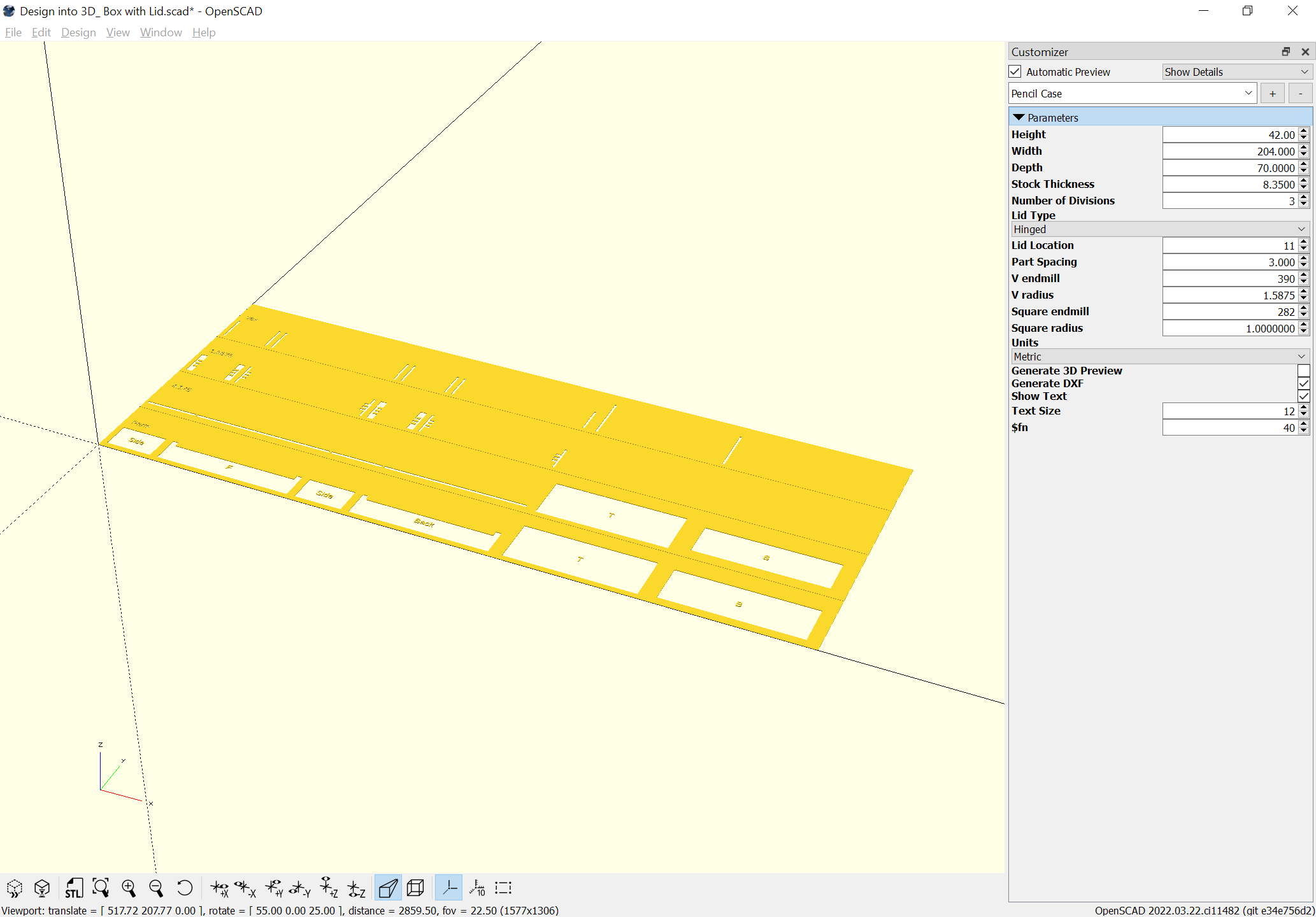
Then toggle off the 3D view and enable generating the DXF:
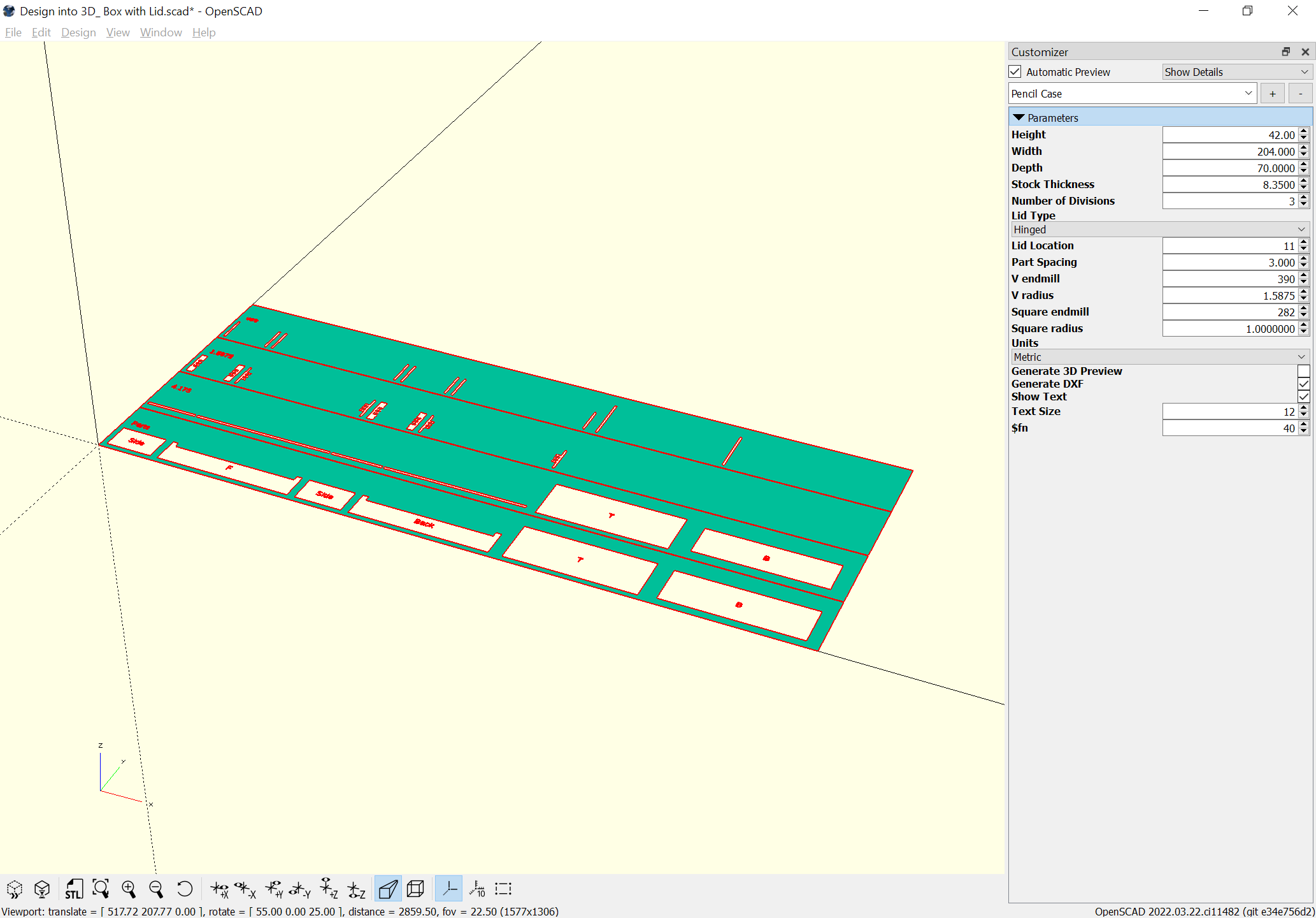
and Render the file:
so that it may be exported to a DXF or SVG:
which loads into Carbide Create as expected:
2 Likes
WillAdams
May 1, 2022, 5:13pm
2
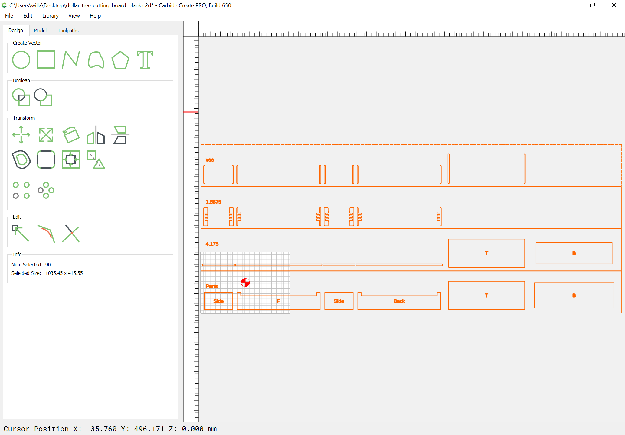
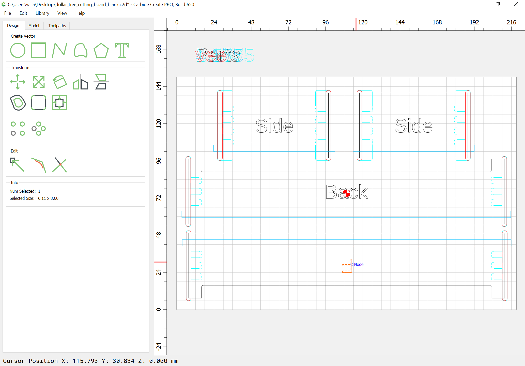
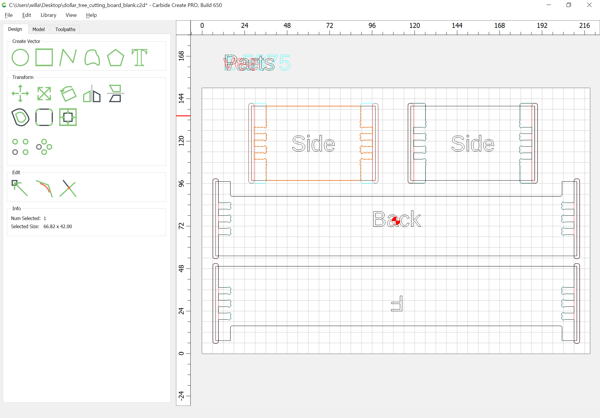
In Carbide Create, set the stock area to match the bounds of a single set of parts:
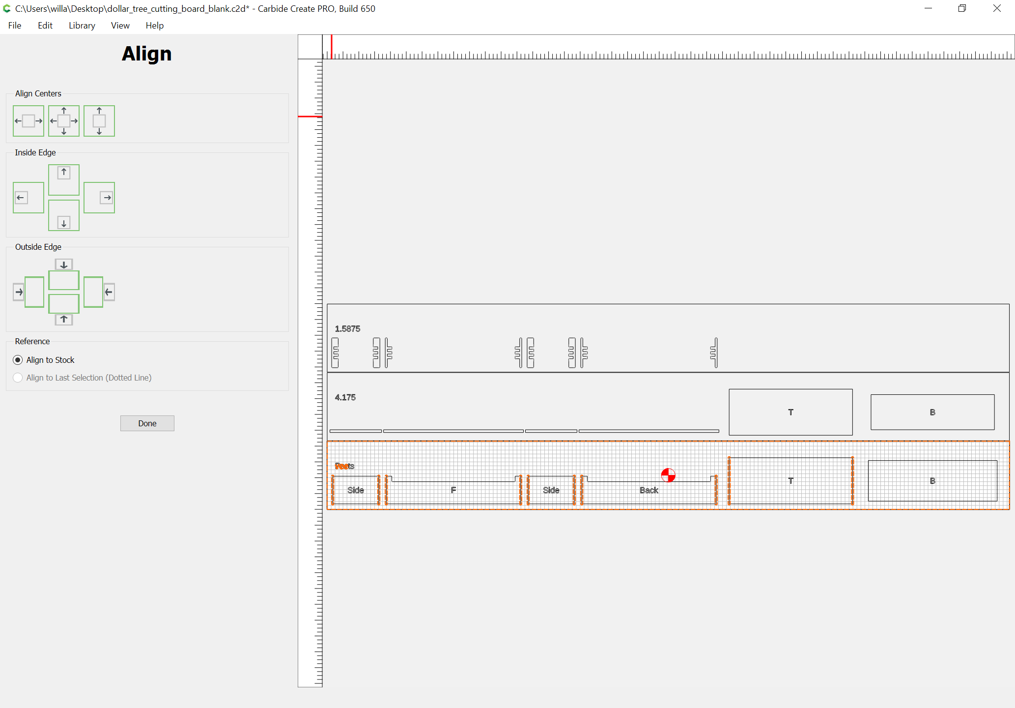
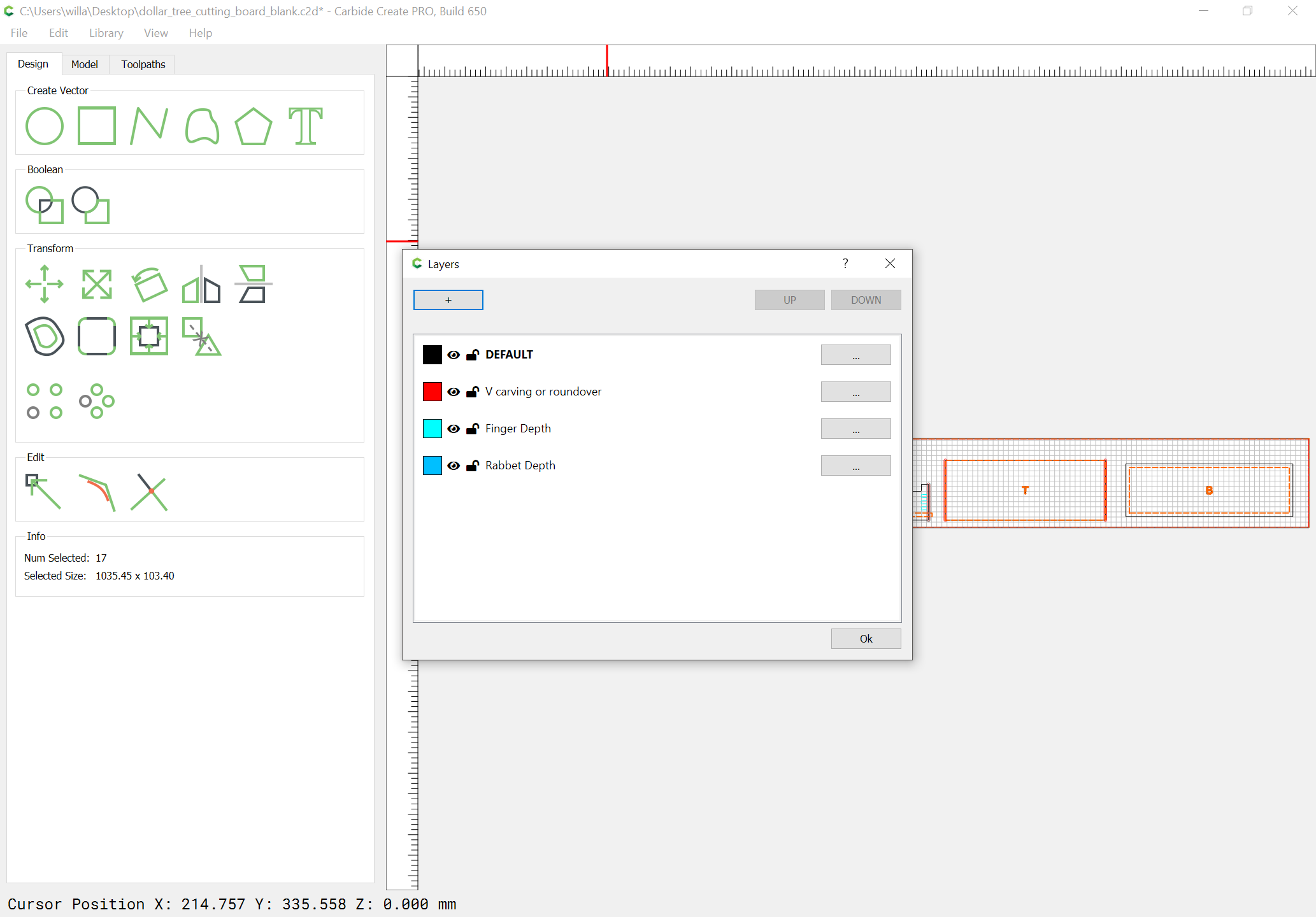
Then create a Layer for each thickness or tool type used in the design, group the matching parts, move them to the appropriate layer and align the group to the Stock Area:
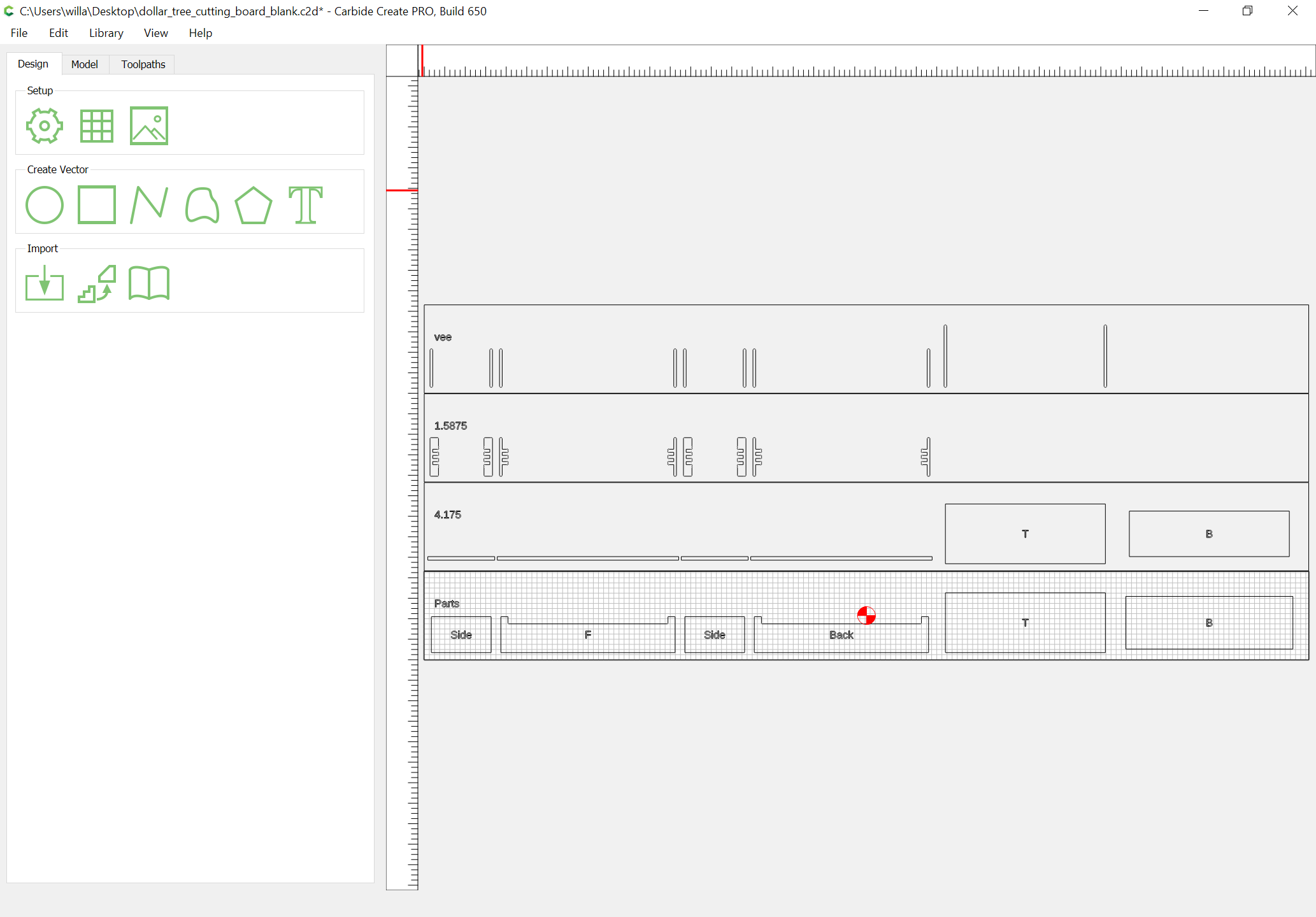
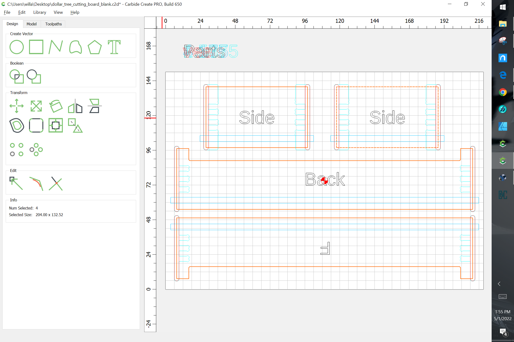
Adjust the Stock Area to match the actual stock which will be used for cutting:
and arrange parts to efficiently use the stock:
1 Like
WillAdams
May 1, 2022, 6:04pm
3
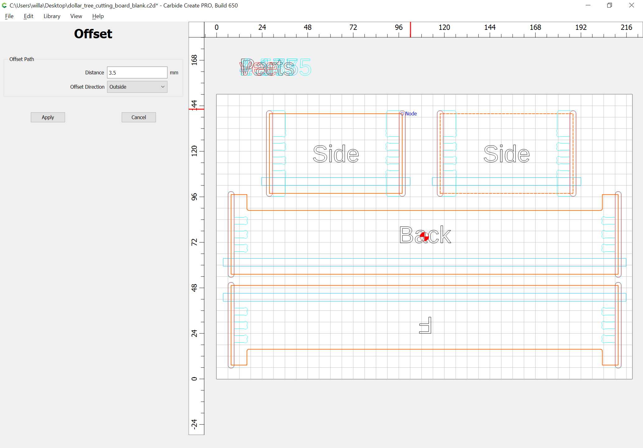
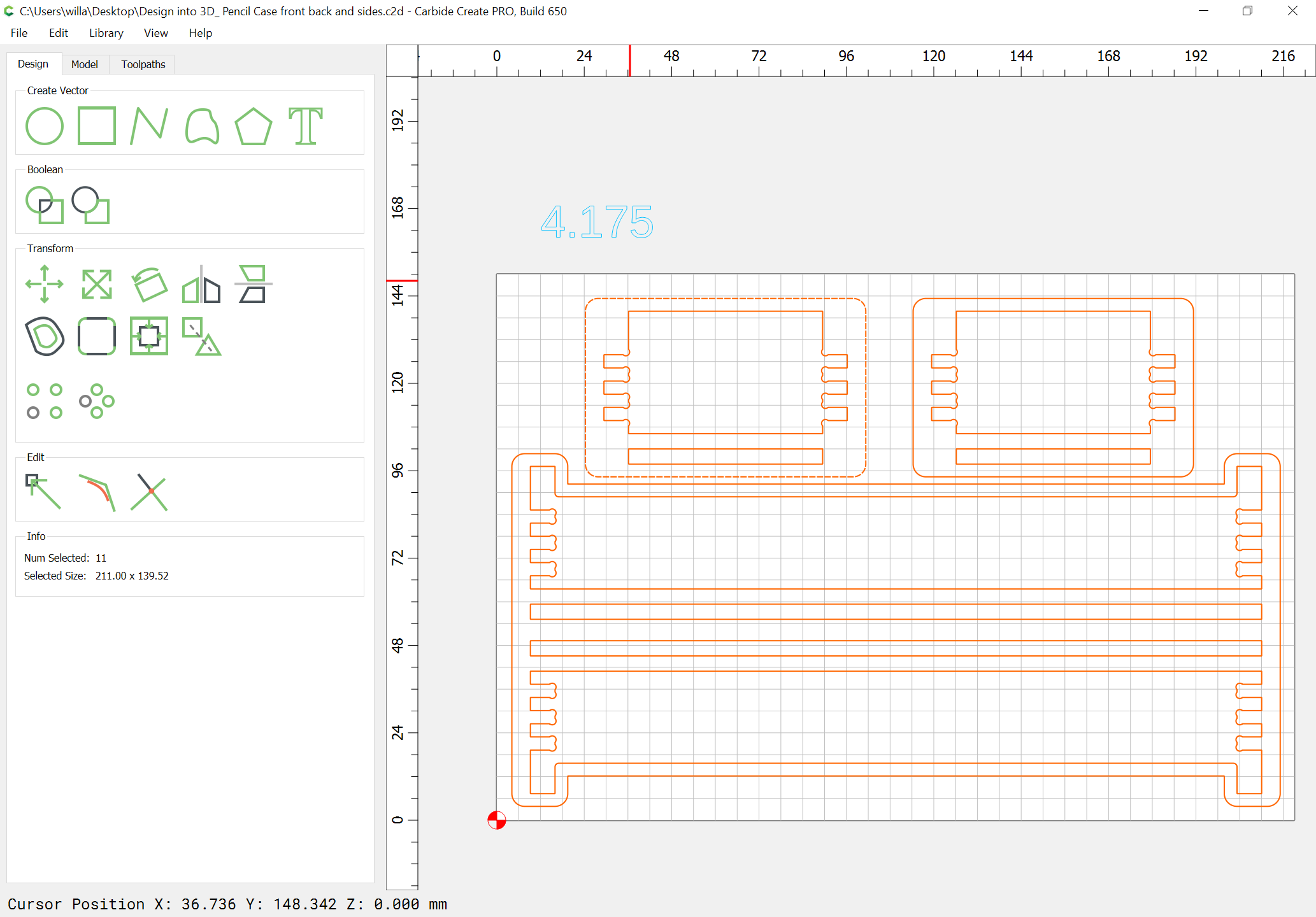
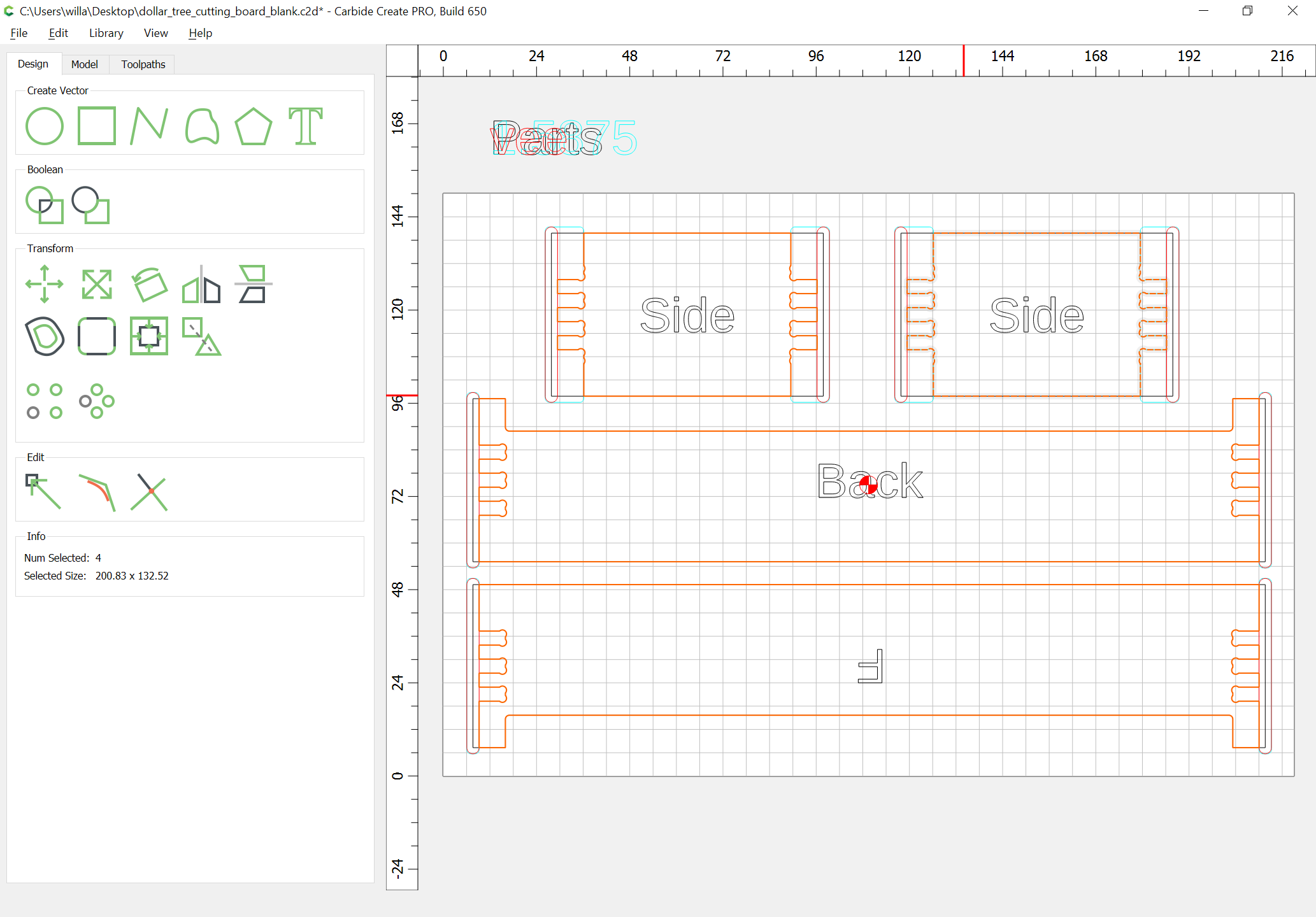
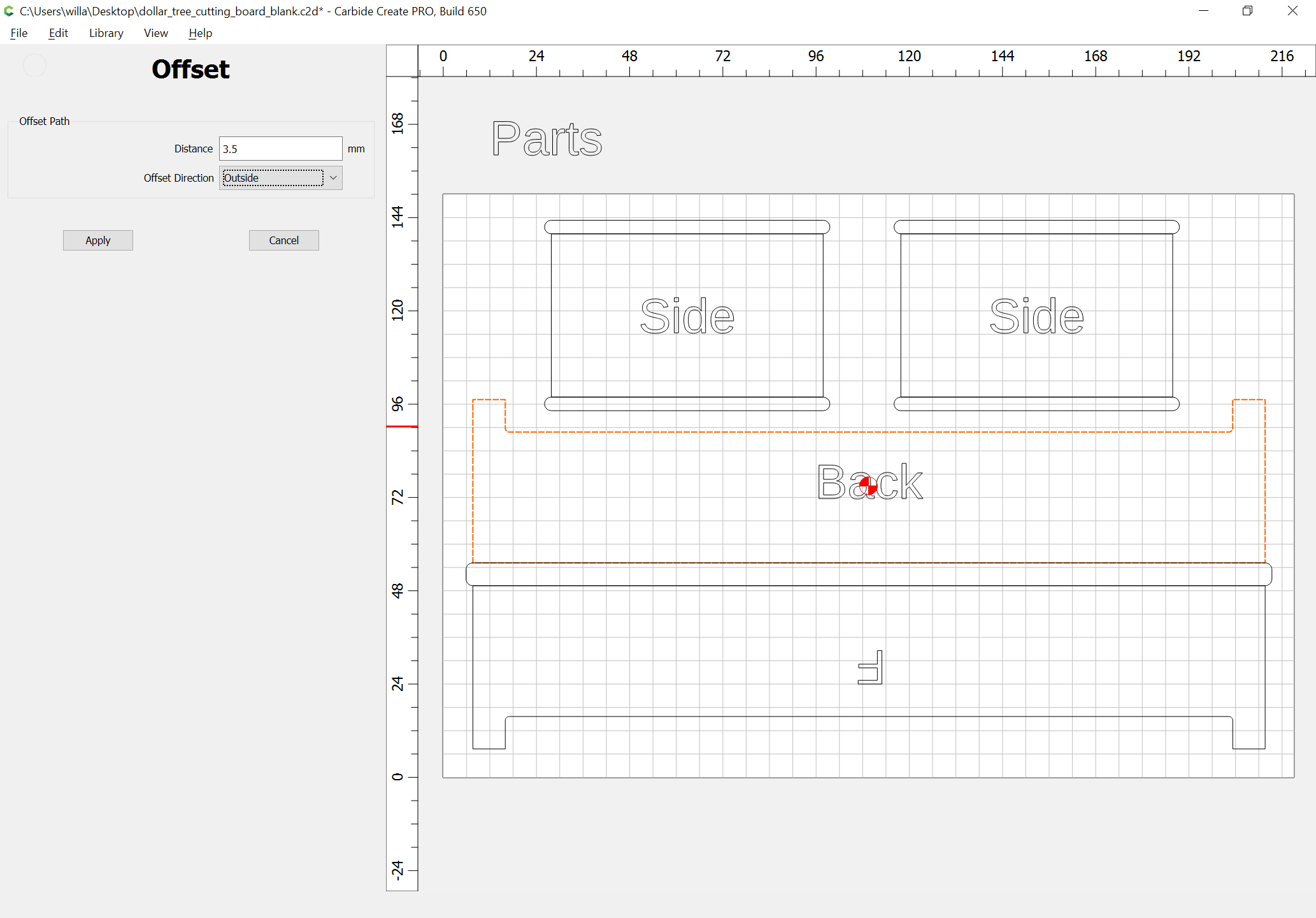
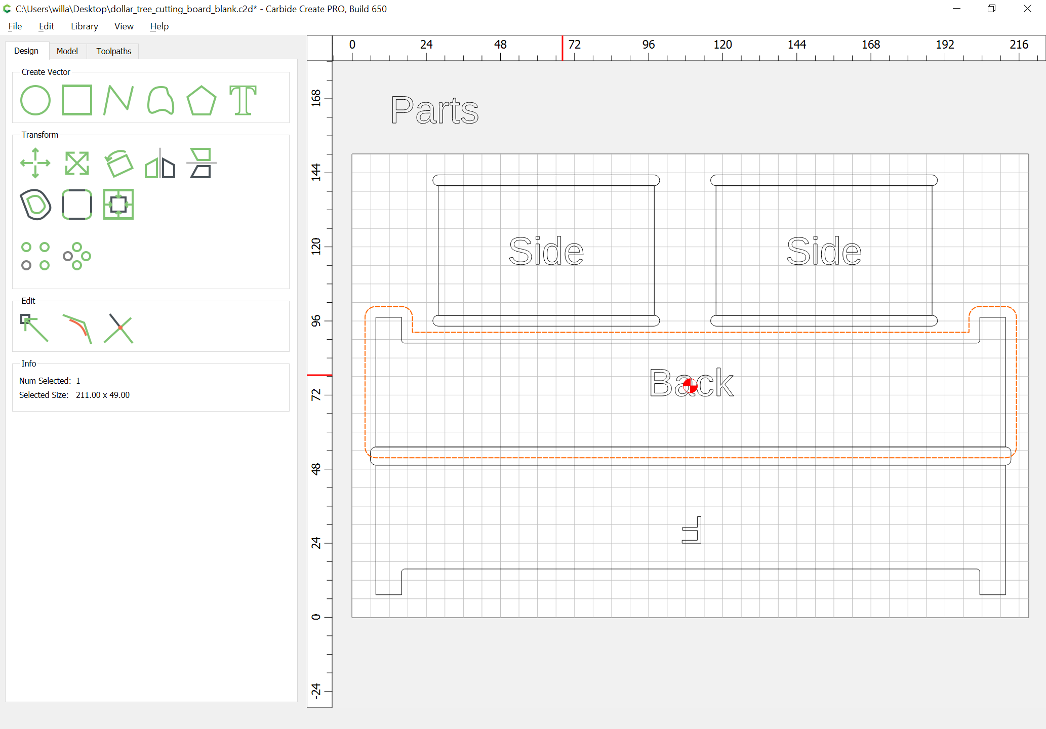
Select the part outlines and offset to the outside by the diameter of the endmill plus 10%:
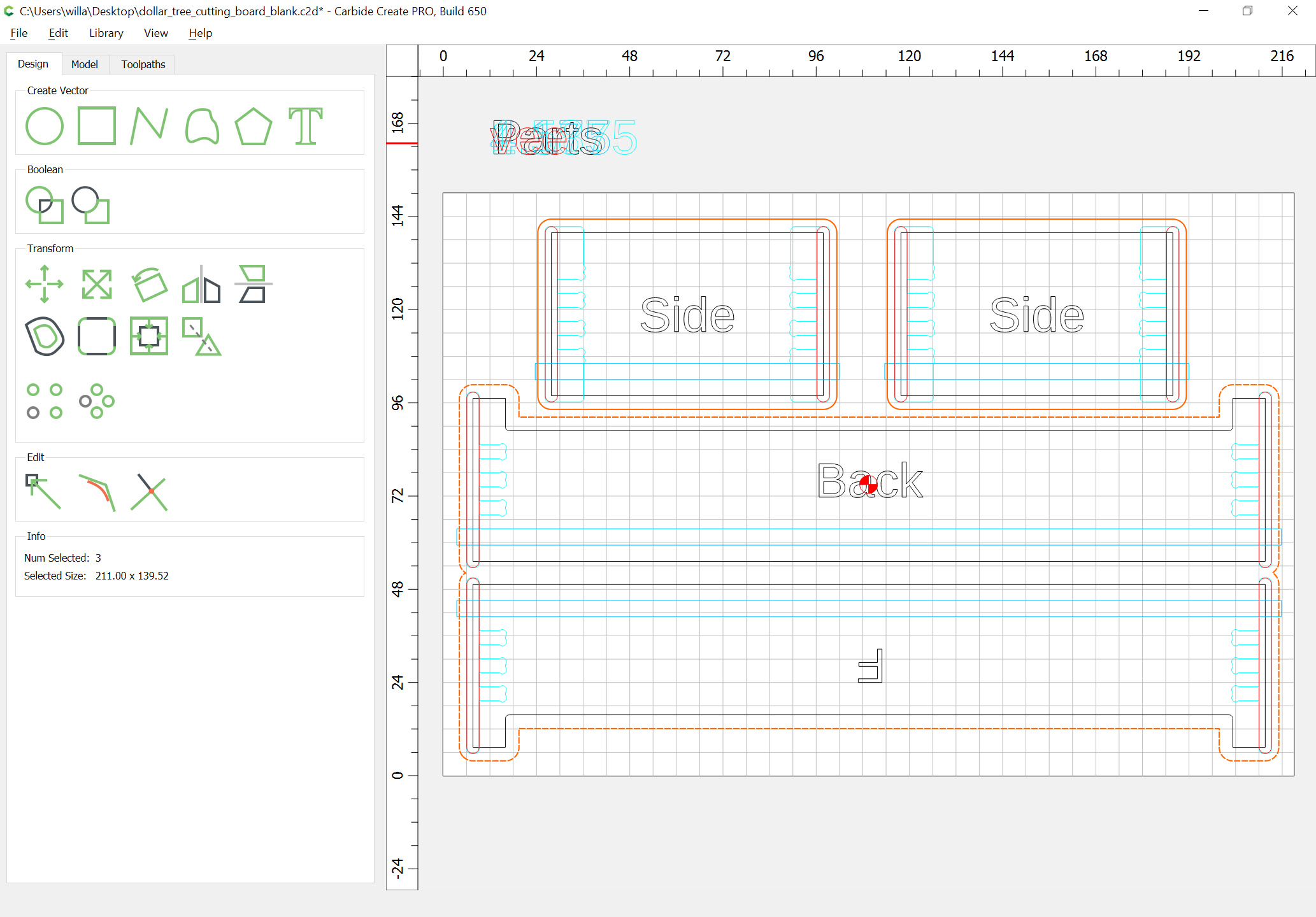
Clean up where appropriate:
and duplicate the geometry which is affected by the rabbets so that the rabbets can be punched out:
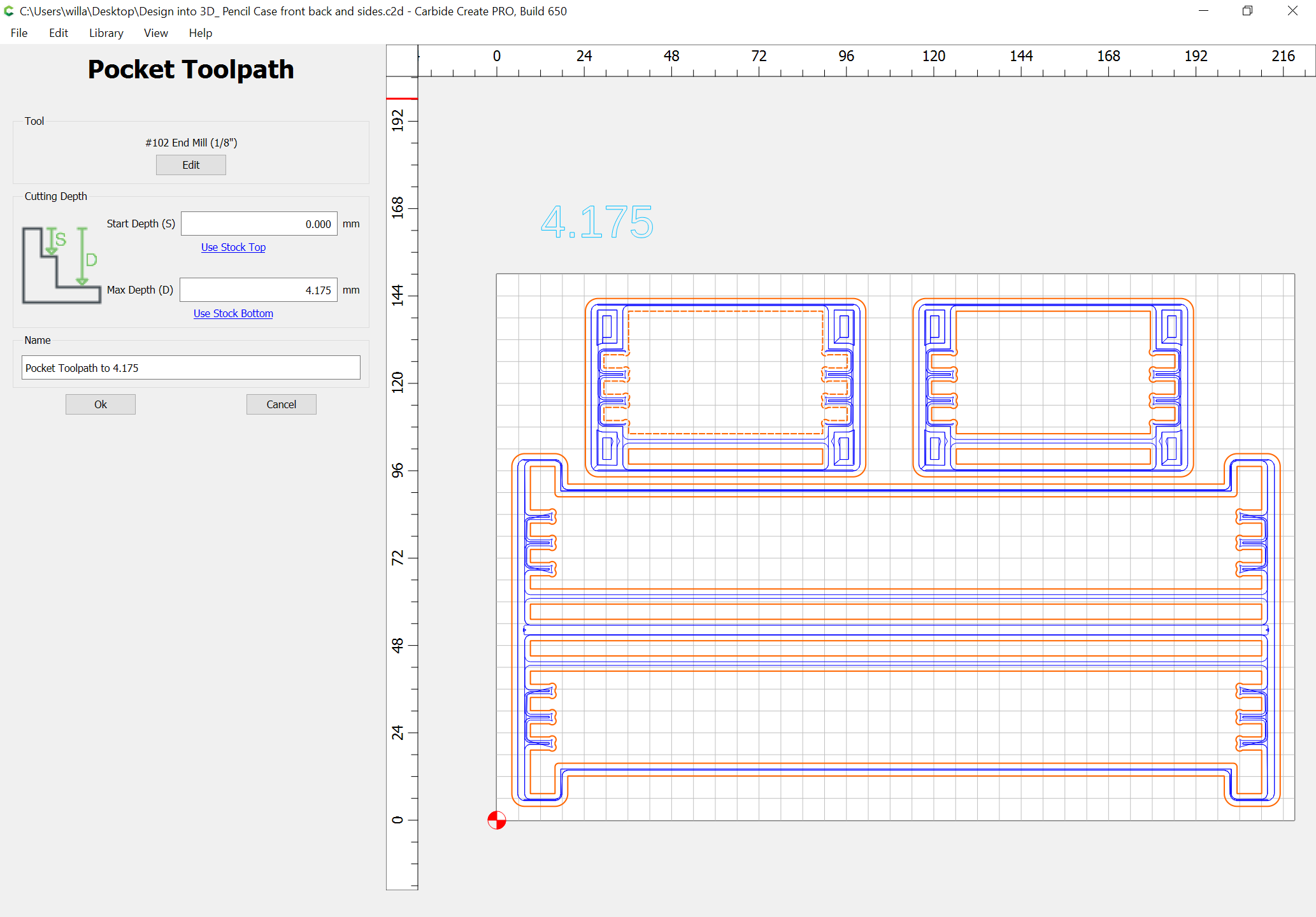
Then select the outer geometry and set up a Pocket toolpath to the rabbet depth:
1 Like
WillAdams
May 1, 2022, 8:25pm
4
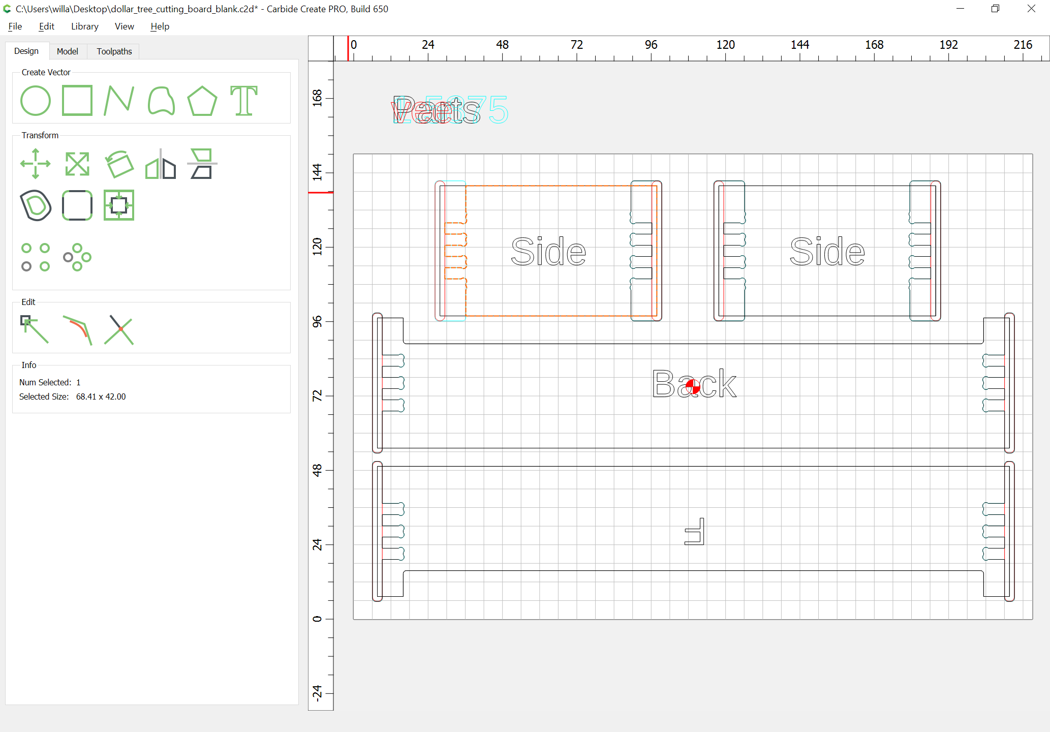
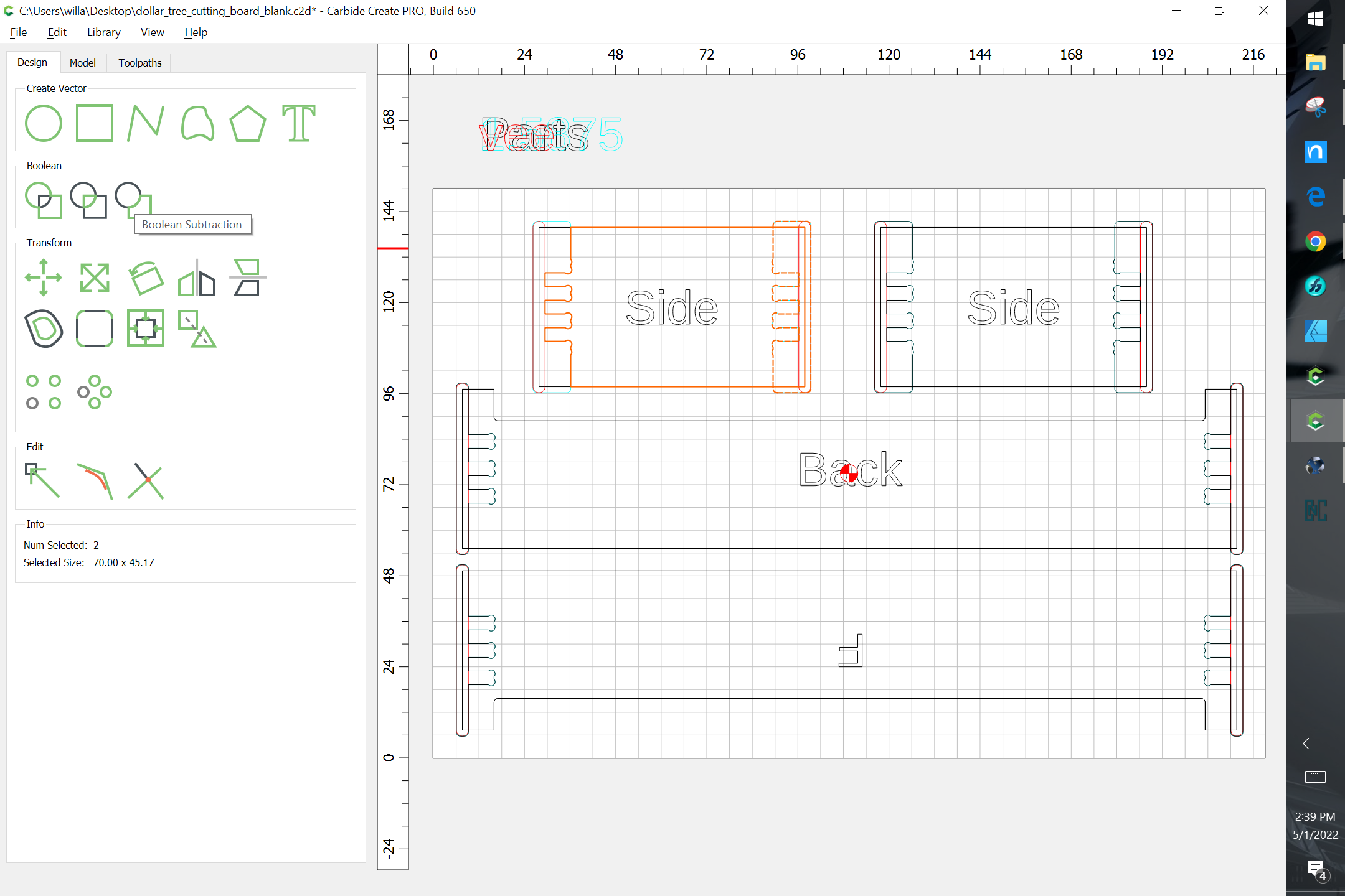
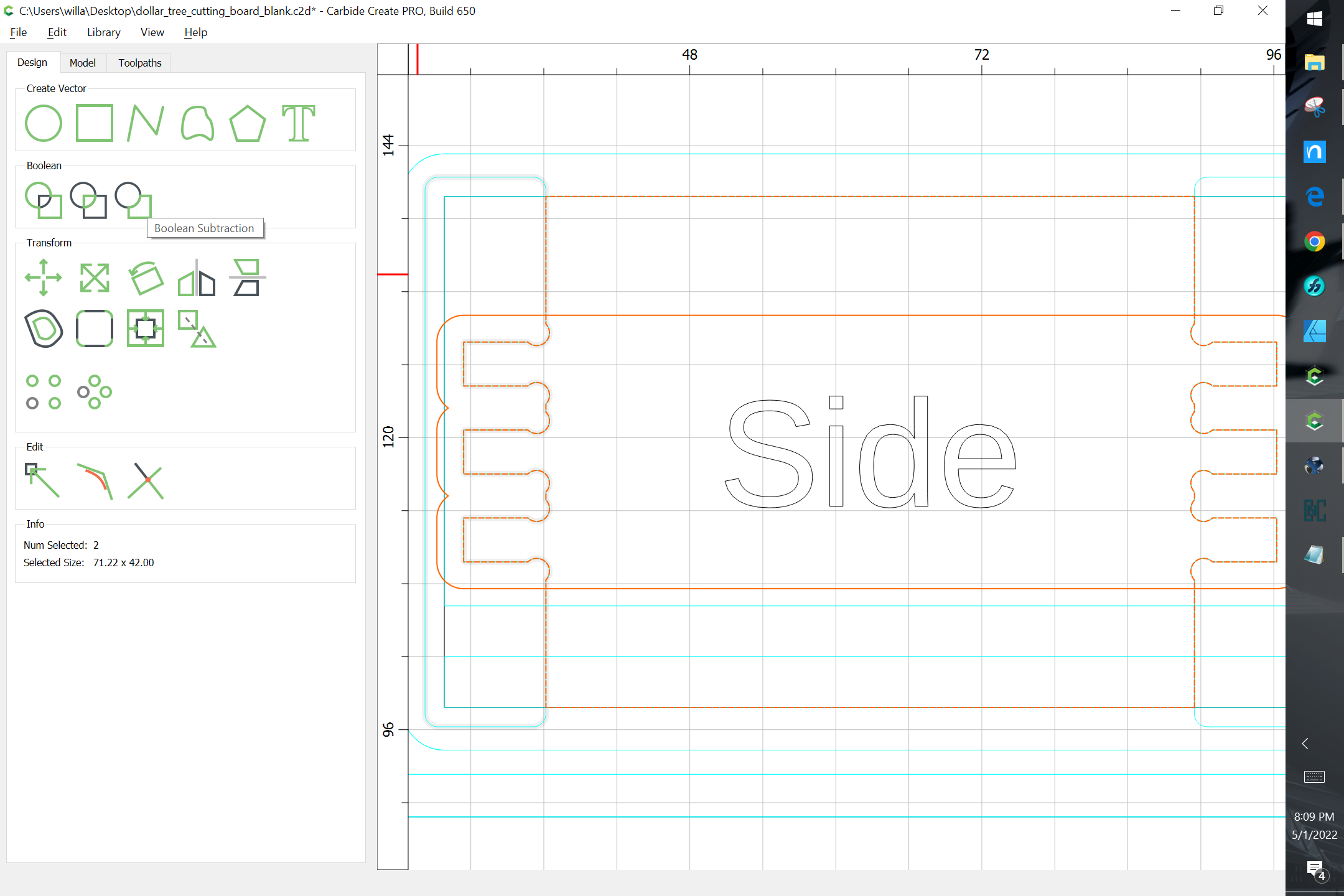
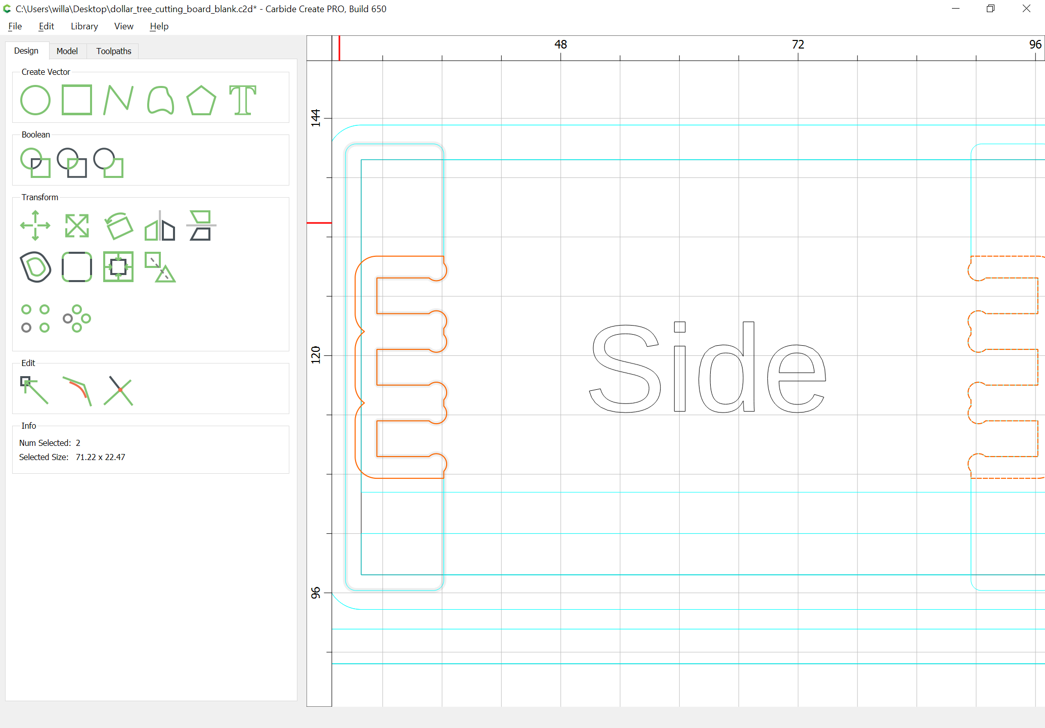
Select the geometry for the box joints and copy-paste it in place:
Then Boolean subtract the joint geometry from the part outlines:
WillAdams
May 1, 2022, 10:06pm
5
Recreate, or copy-paste in-place the surrounding geometry:
select it and the joint-part geometry and define a pocket from rabbet depth down to the joinery depth:
WillAdams
May 2, 2022, 12:10am
7
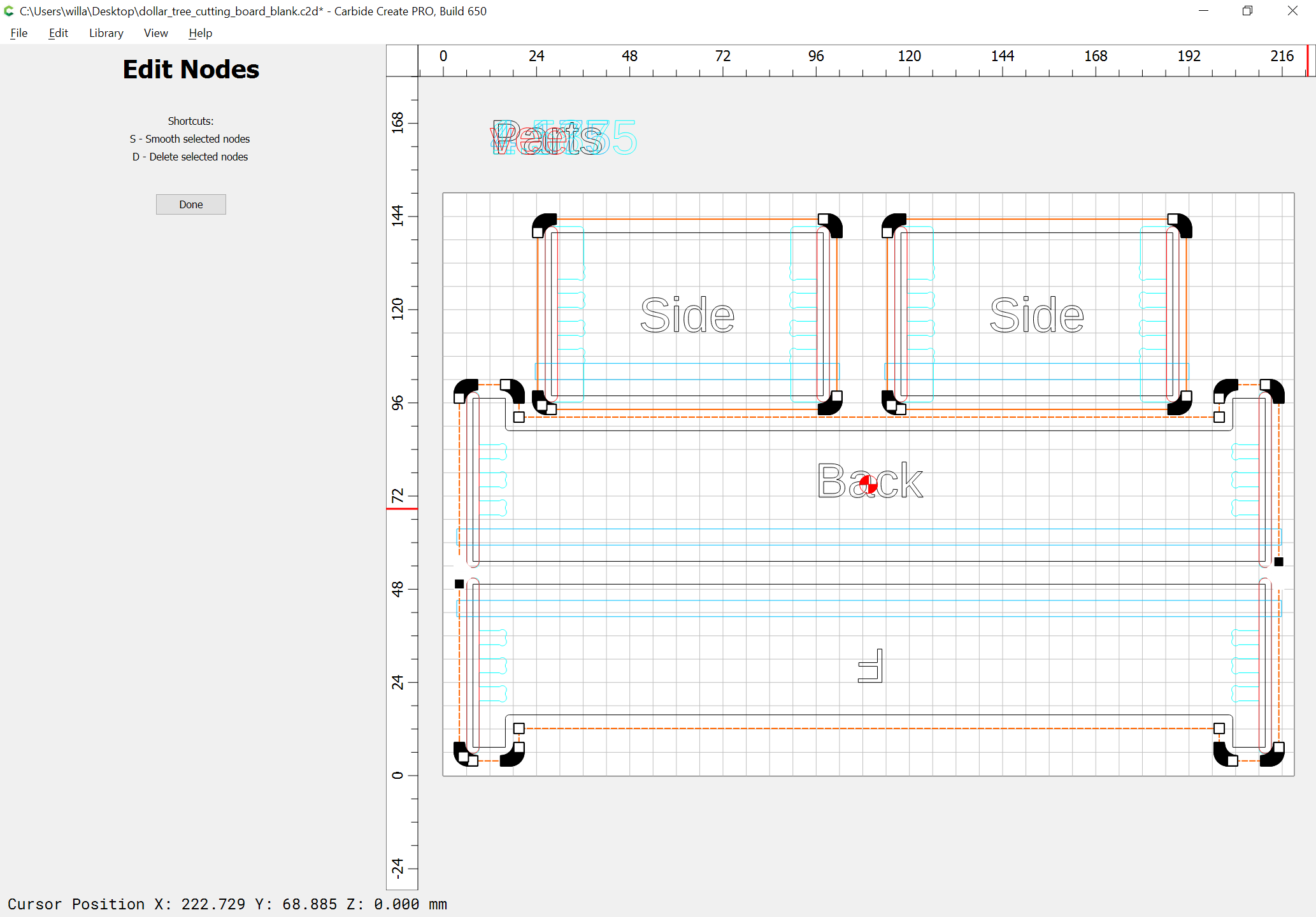
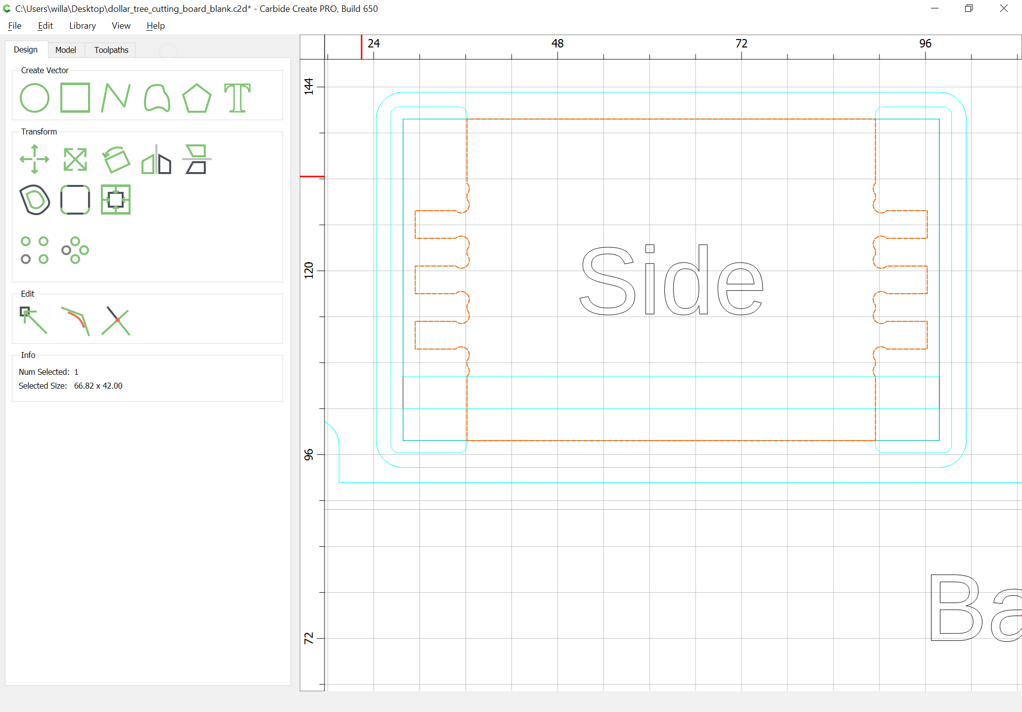
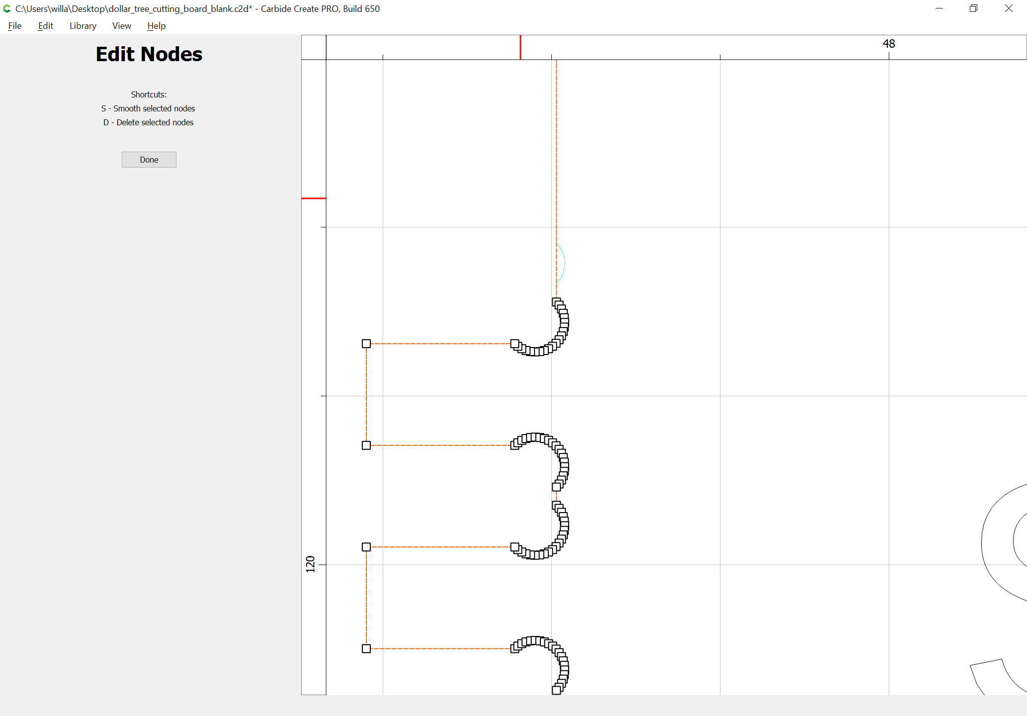
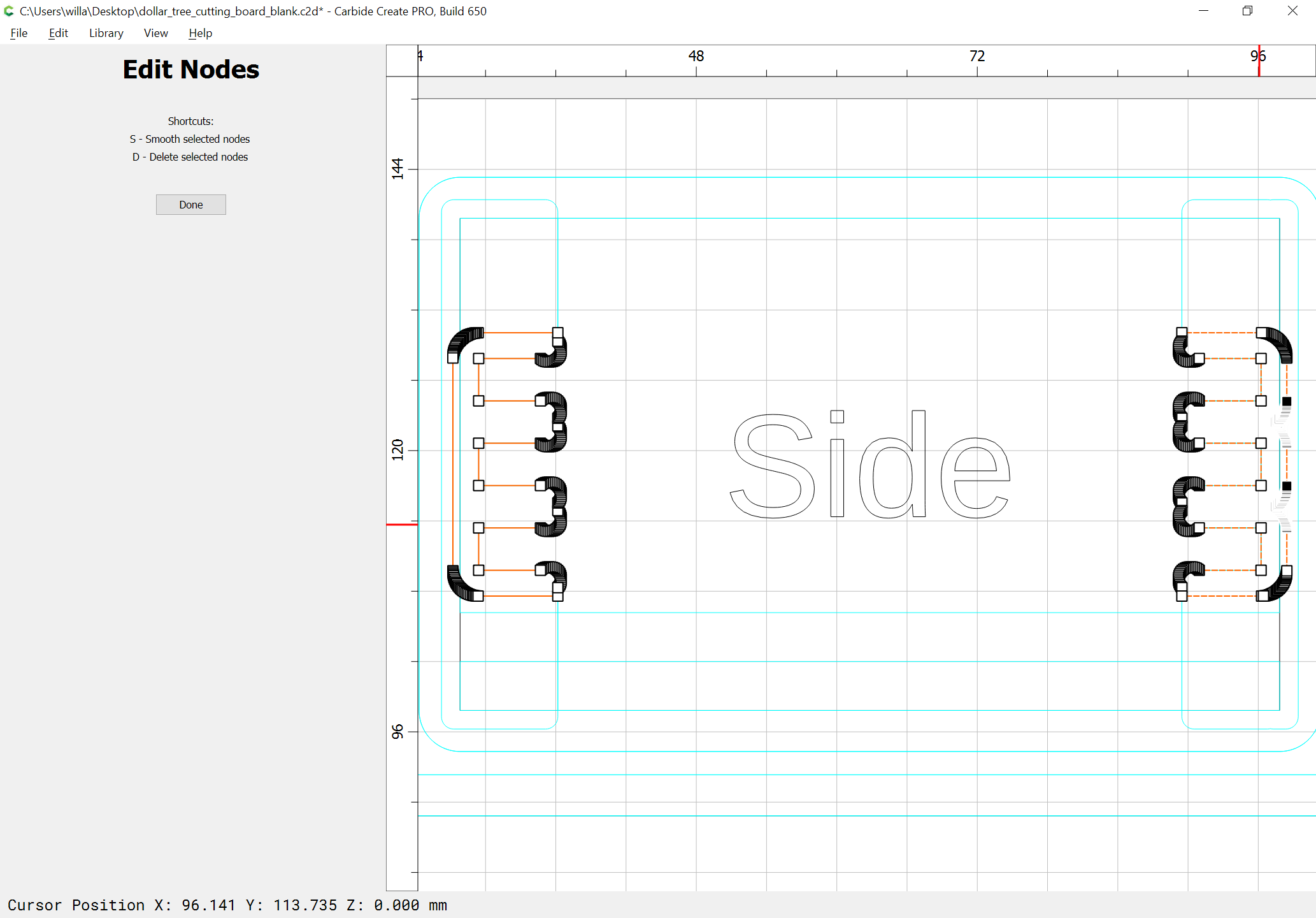
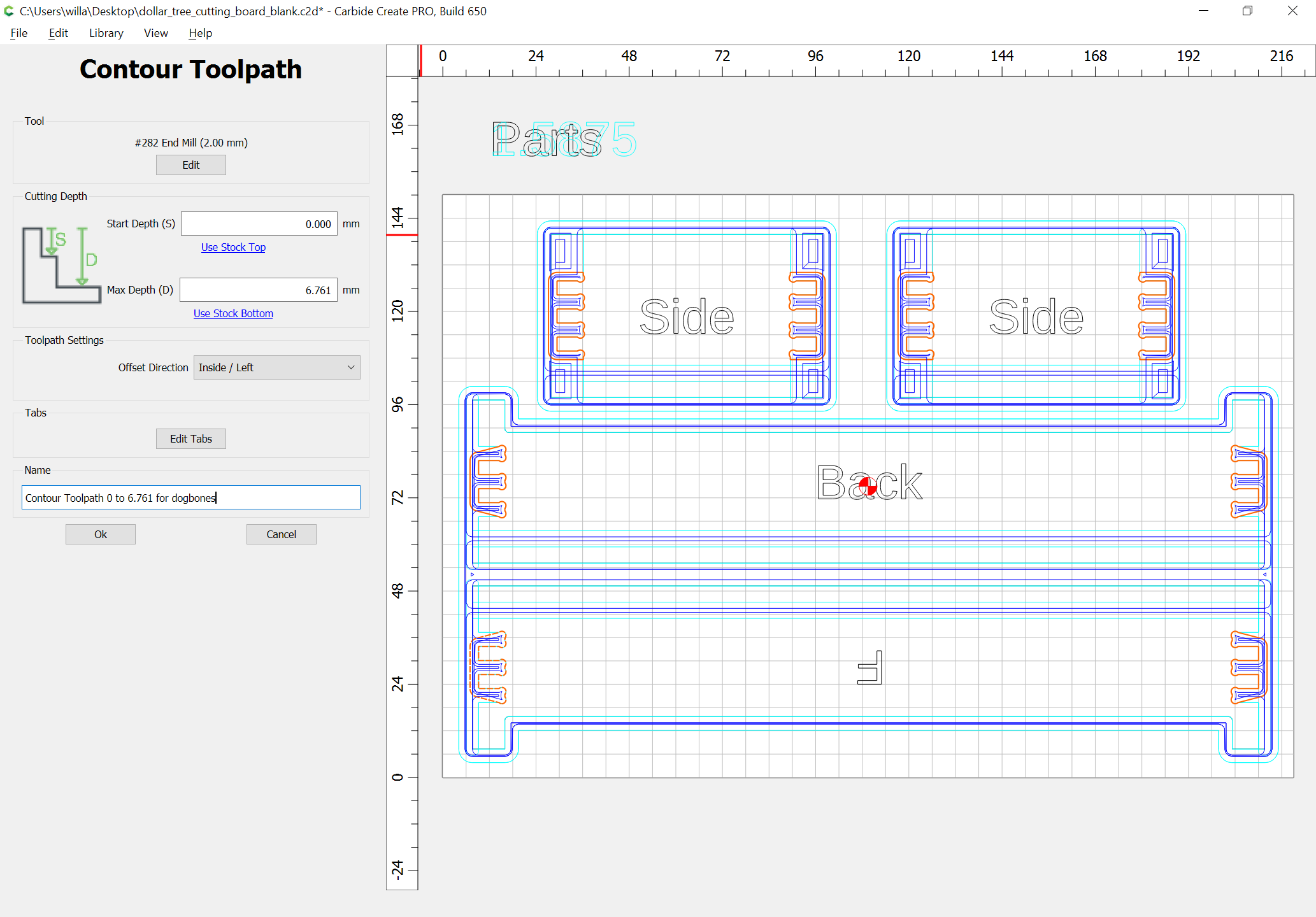
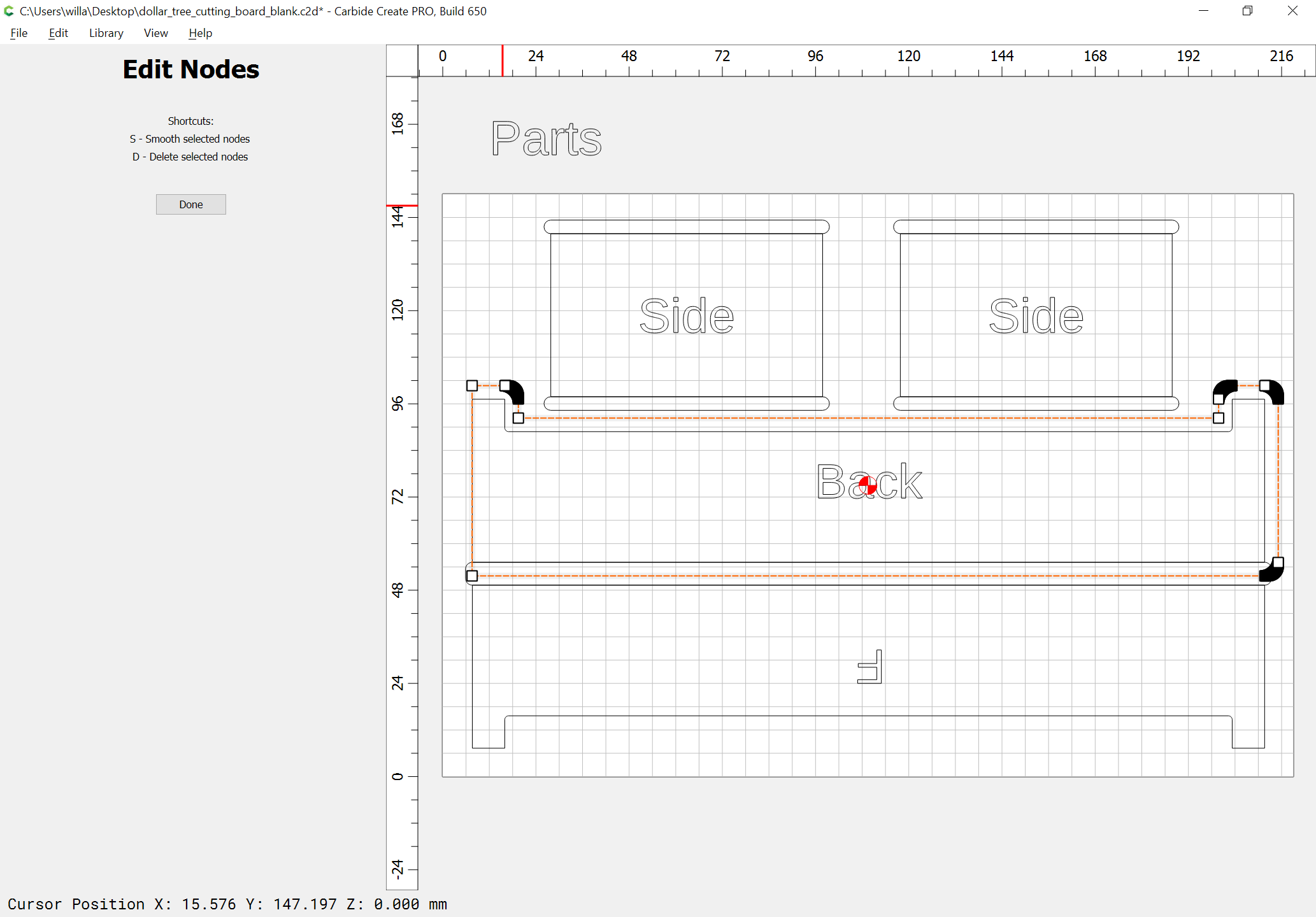
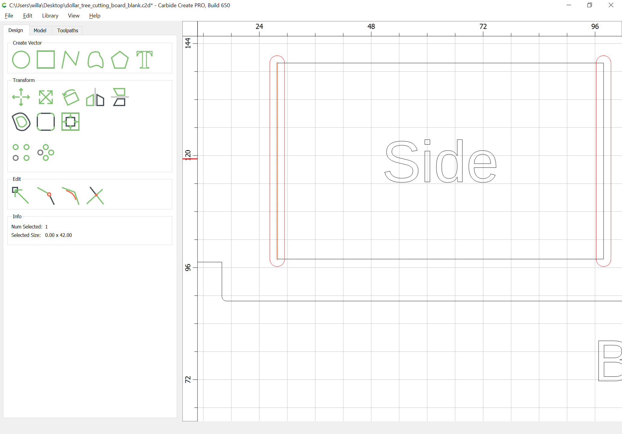
If the endmill used to cut out the joinery is not small enough to cut out the dogbones, it will be necessary to define geometry to make this cut — select the geometry in question:
If need be, clean it up to remove any extraneous dogbones:
(repeat as needed for all copies)
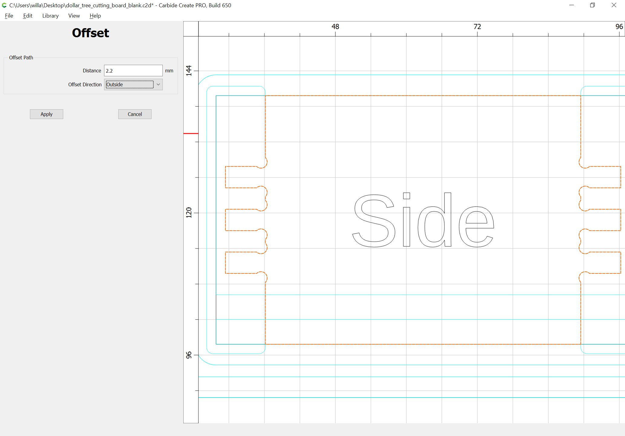
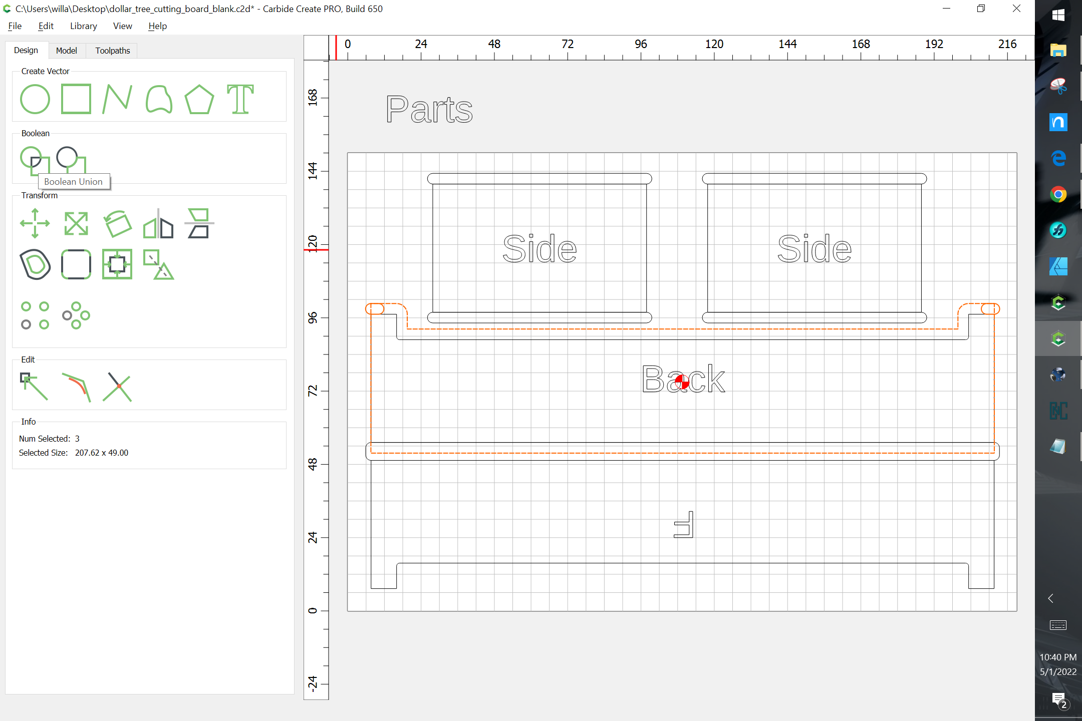
Offset to the outside by the size of the dogbones (should be the small endmill diameter plus 10%):
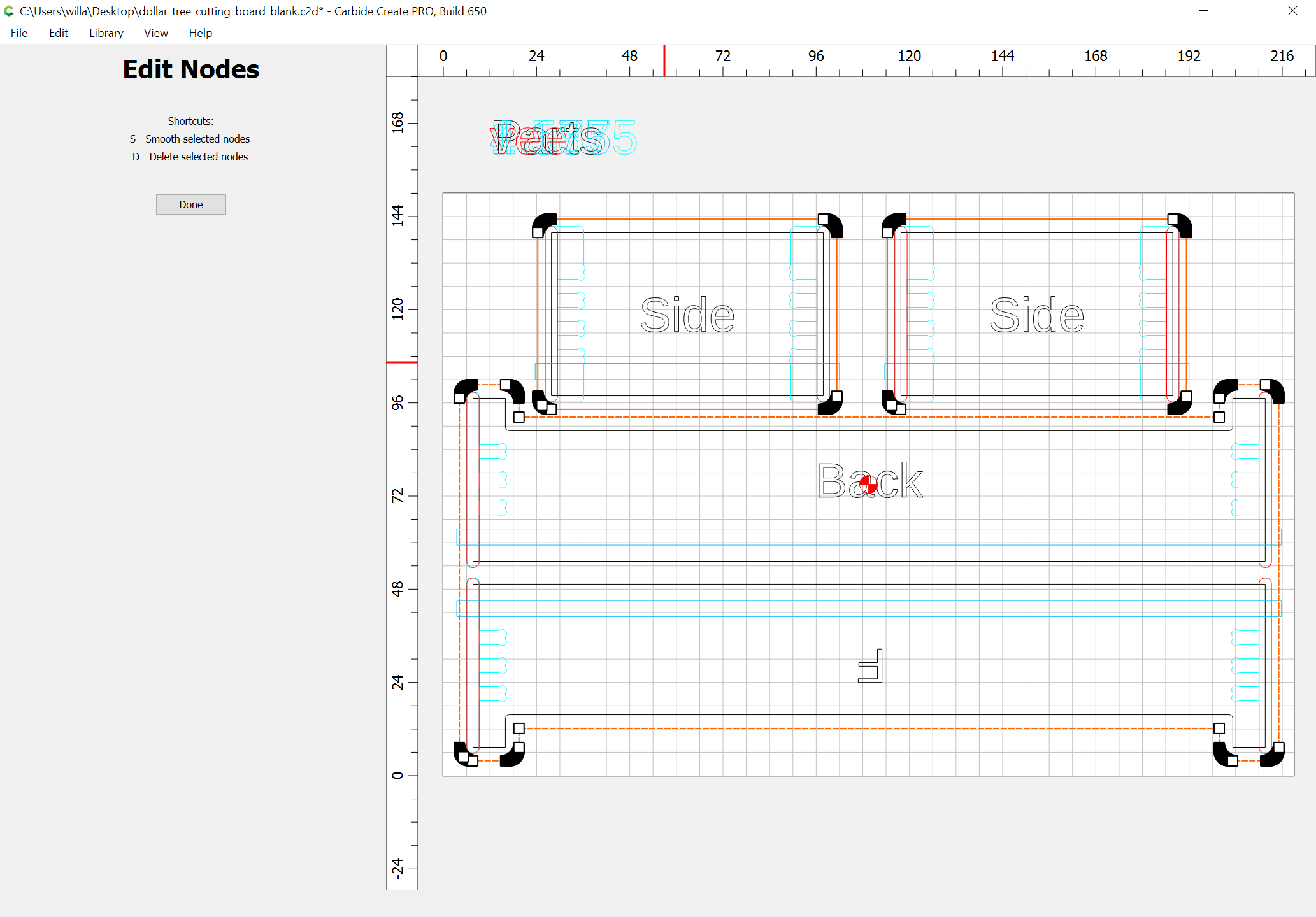
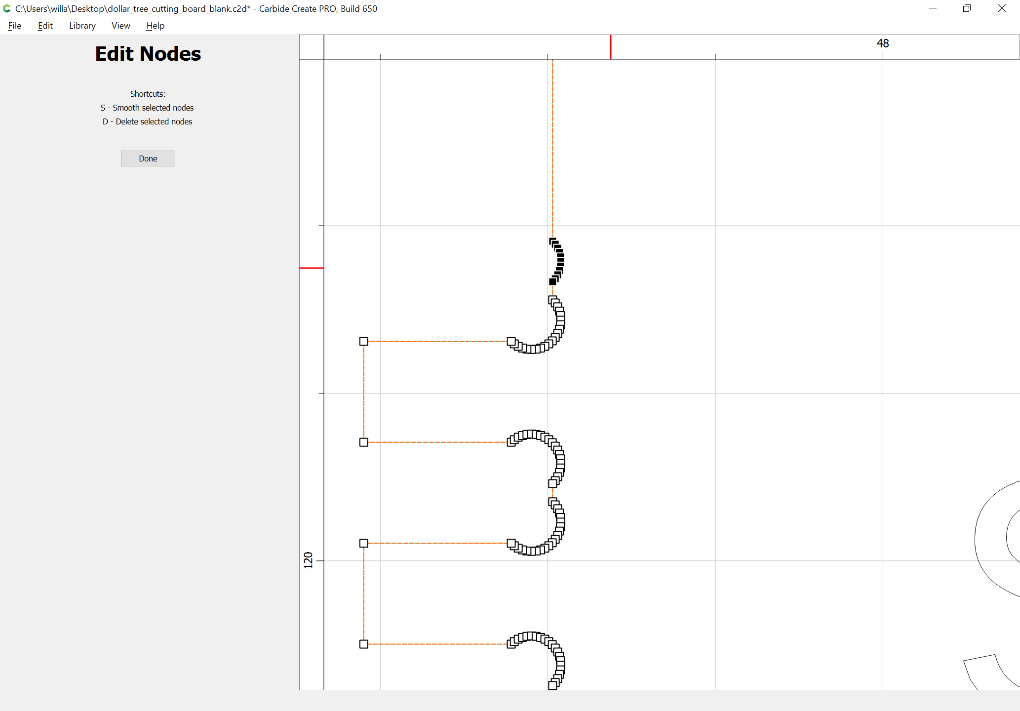
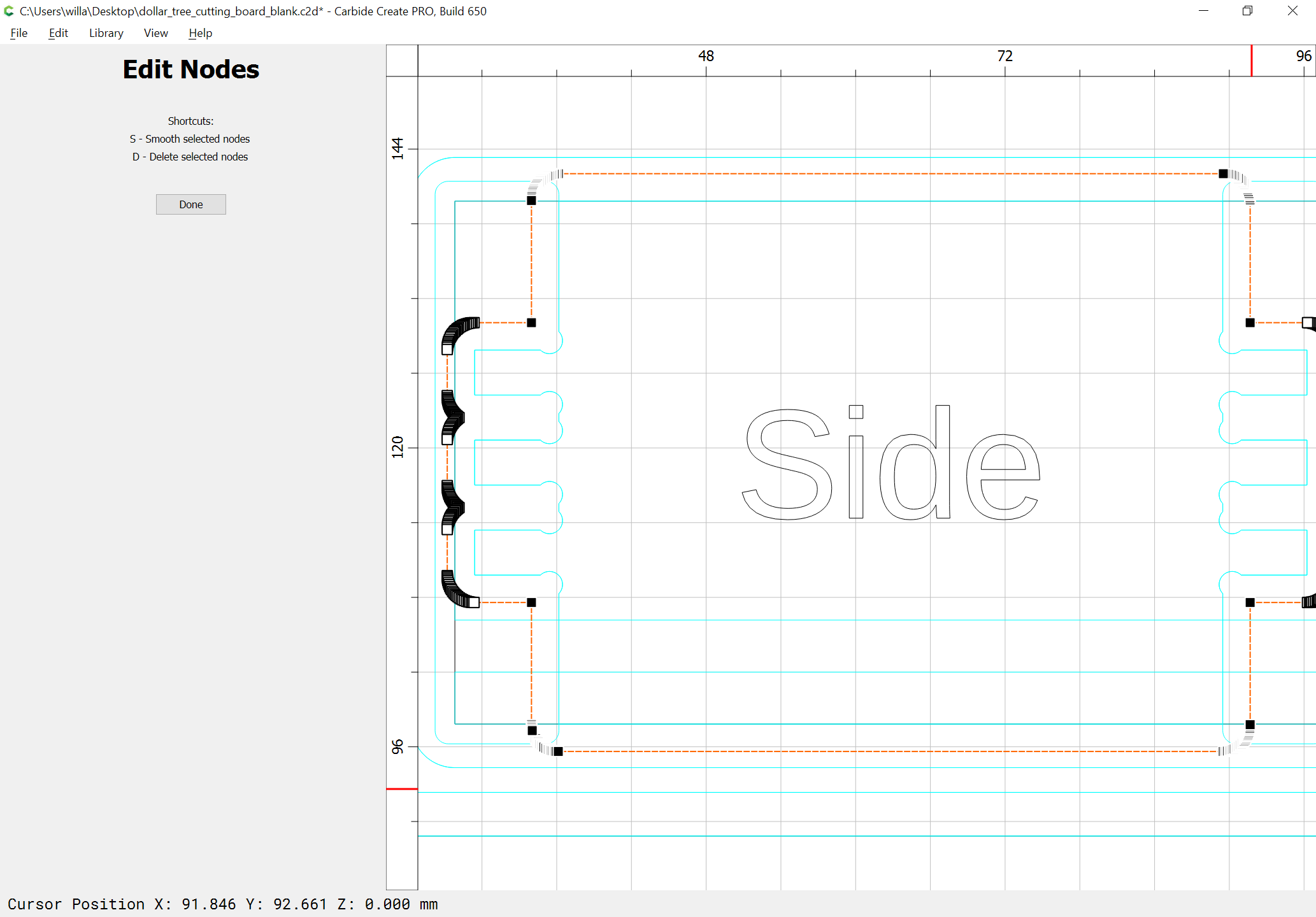
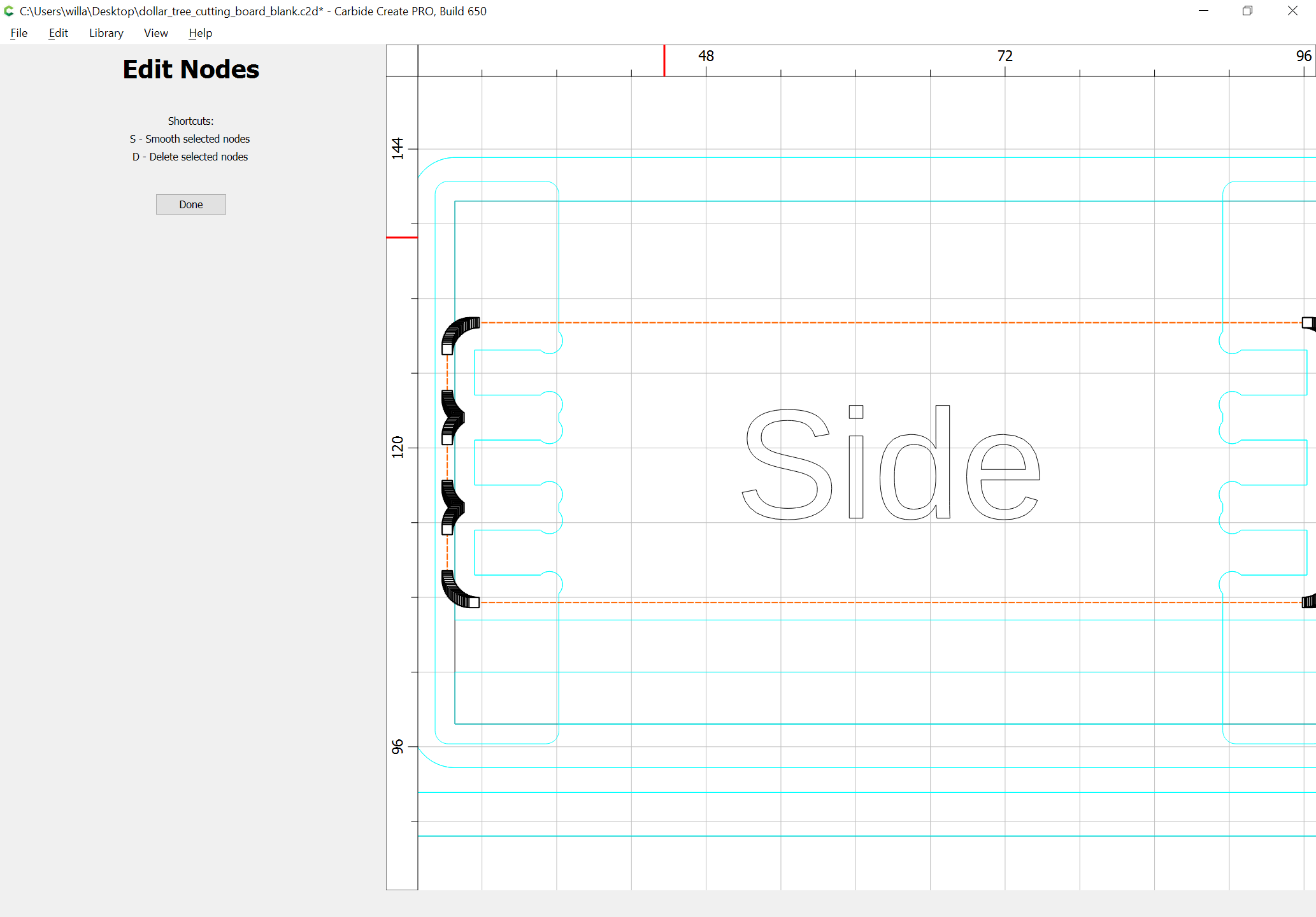
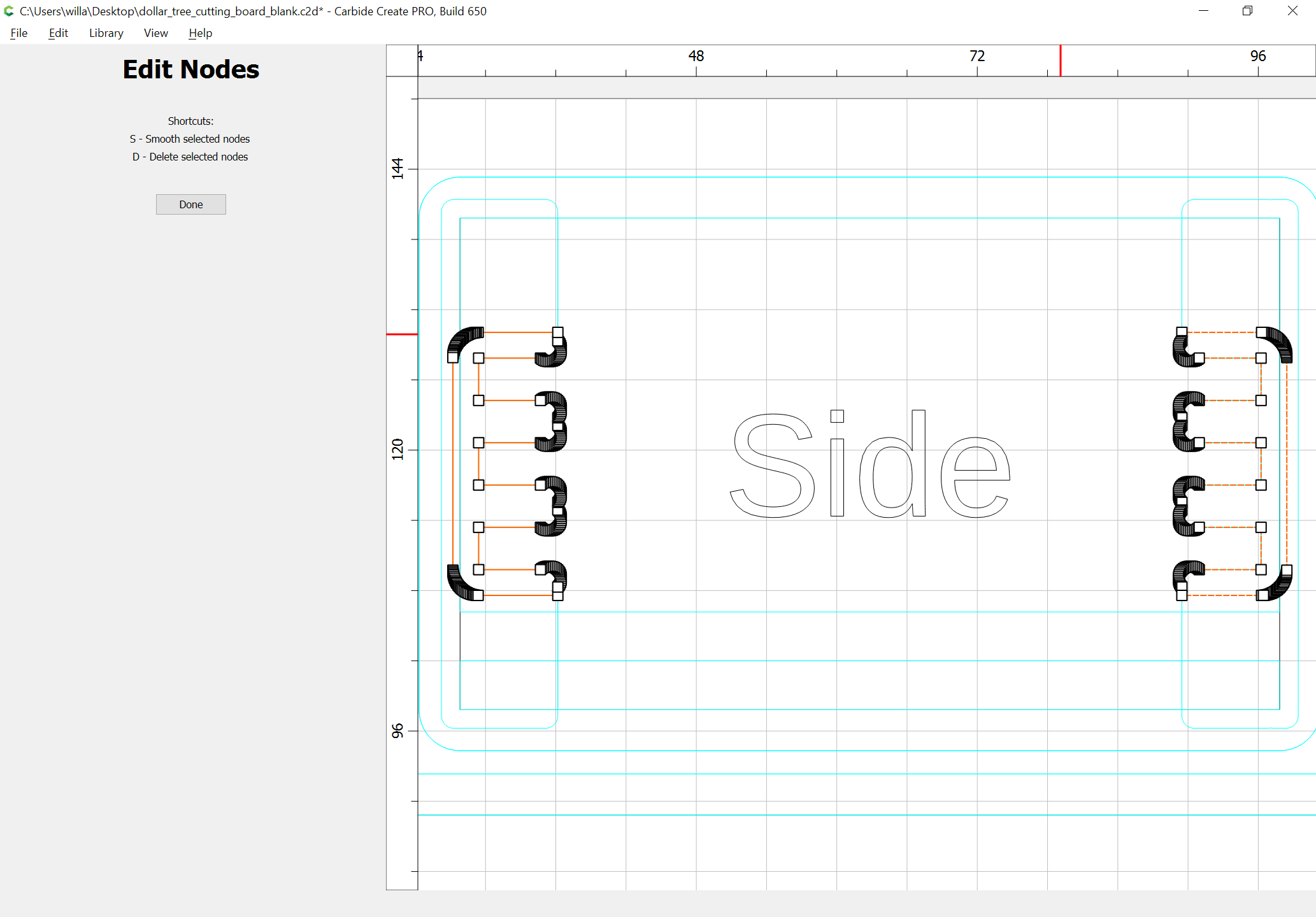
then node edit to limit the geometry to where the cutting actually needs to be cut:
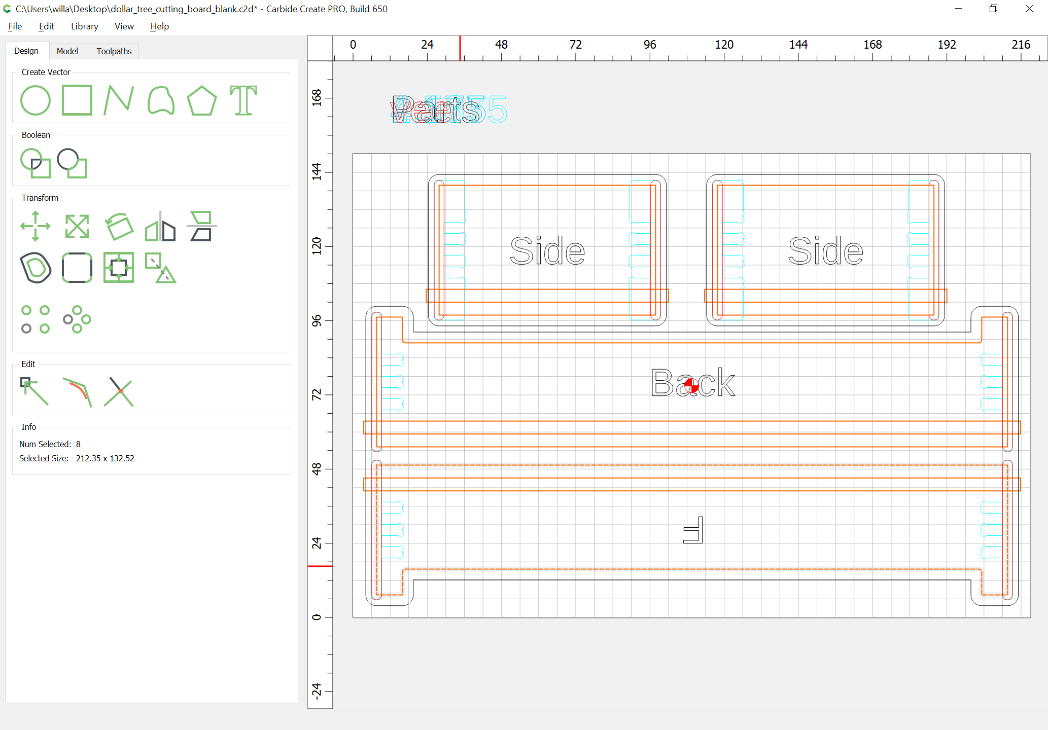
and duplicate the original geometry and punch it out of the offset shape:
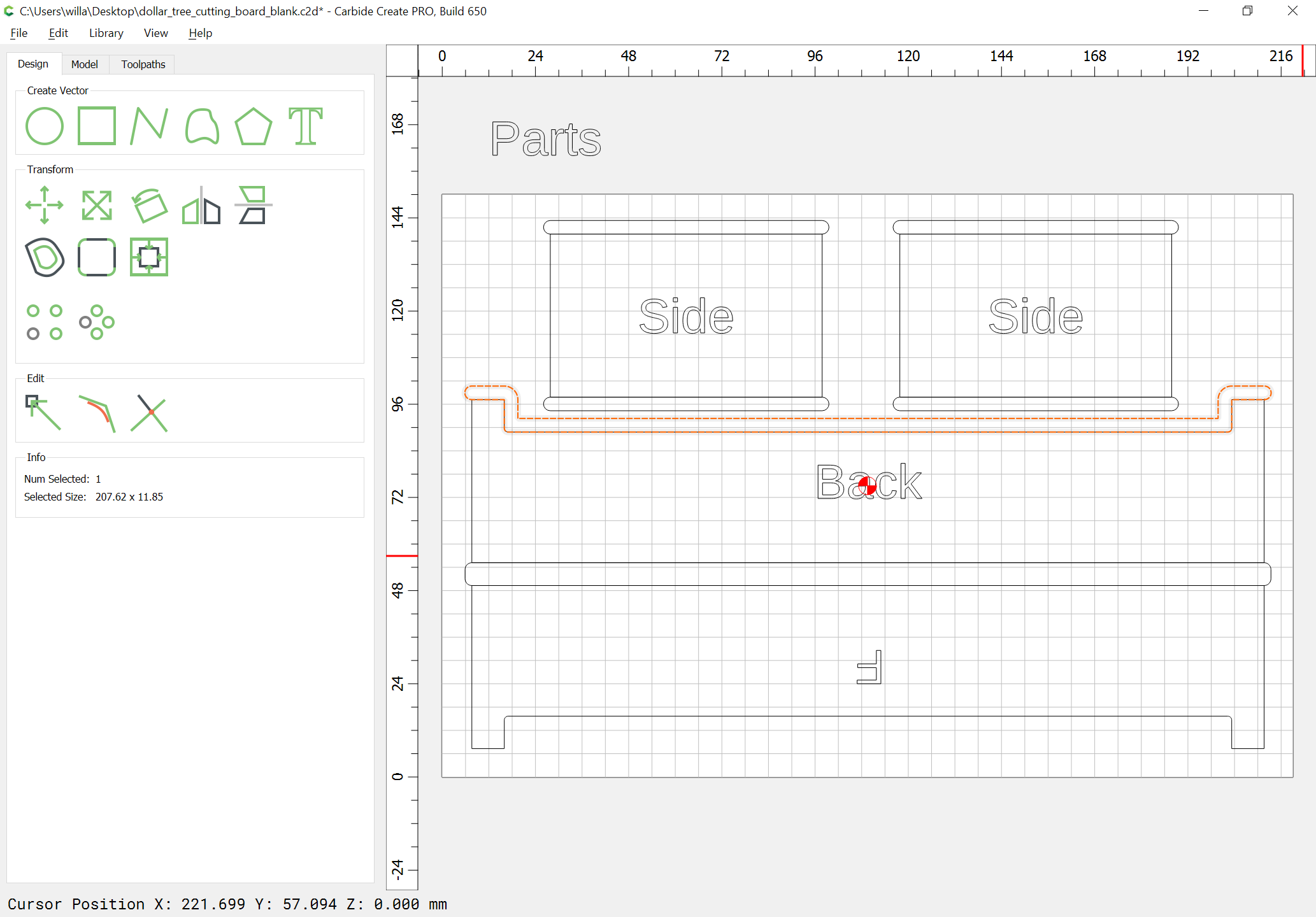
and simplify the geometry to make the cutting more efficient:
WillAdams
May 2, 2022, 12:36am
8
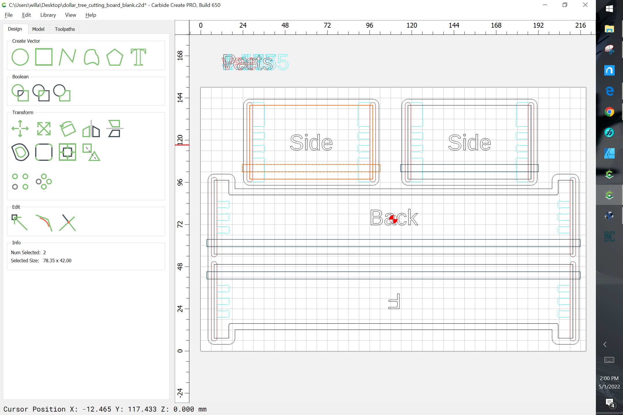
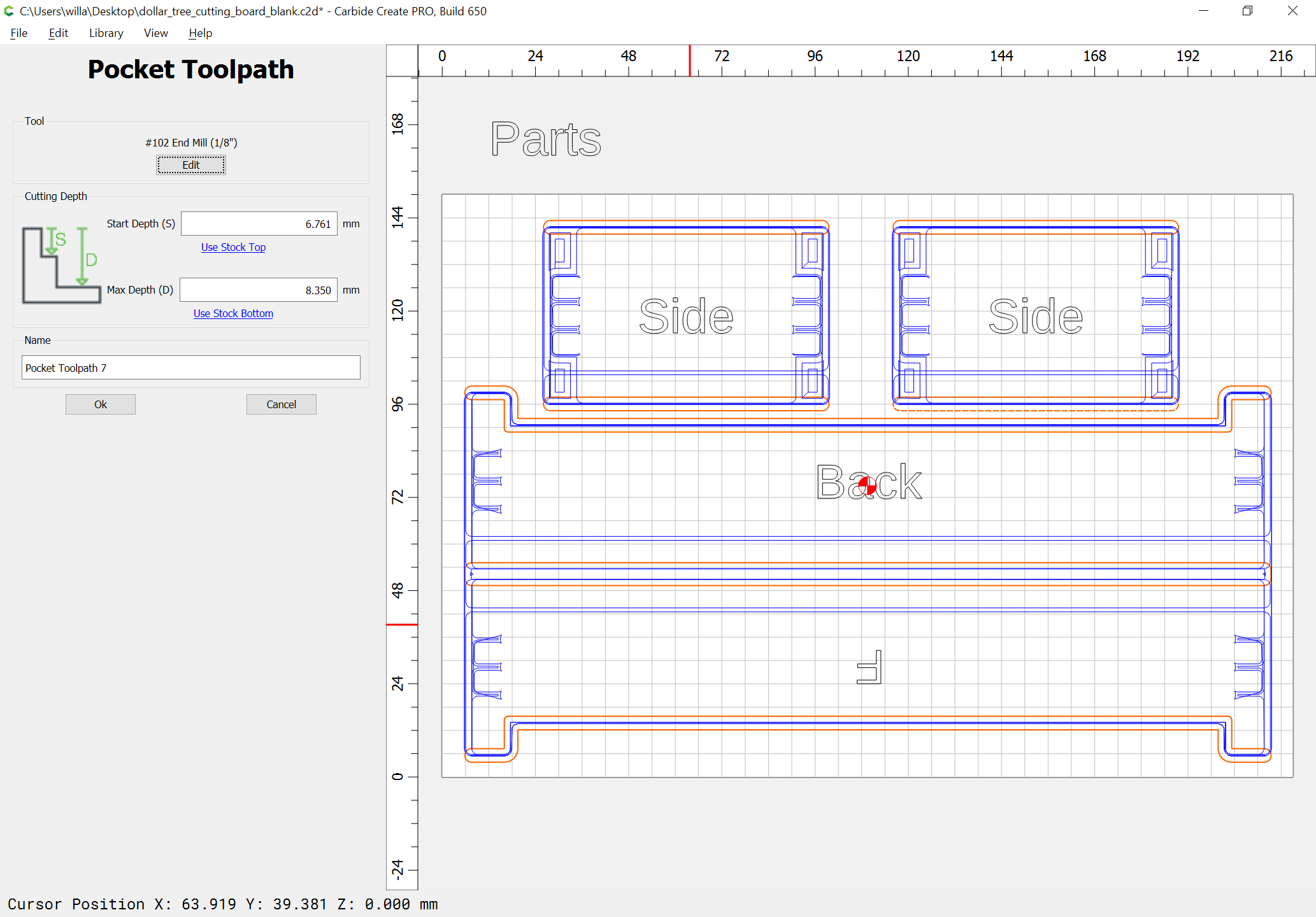
Repeat to then apply a toolpath w/ an inside contour:
WillAdams
May 2, 2022, 2:45am
9
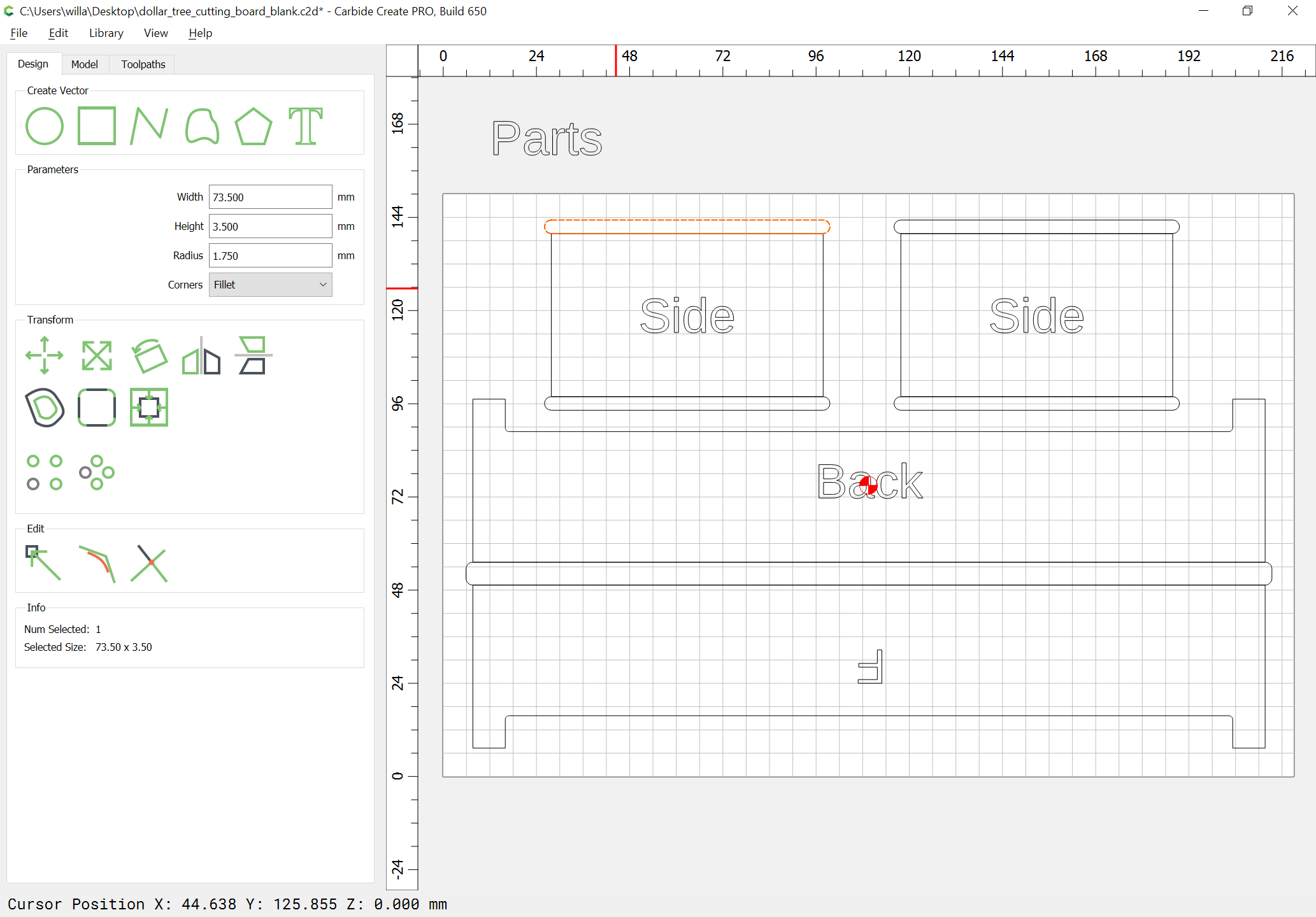
To cut the parts out, we need geometry at the top/bottom of each part — the sides and the bottom of the front are easily done:
While working around the detailing of the tops of the front and back requires a bit of judicious offsetting:
and then node editing:
then assign a pocket toolpath which starts at the bottom of the joint depth pocket and cuts through:
WillAdams
May 2, 2022, 2:45am
10
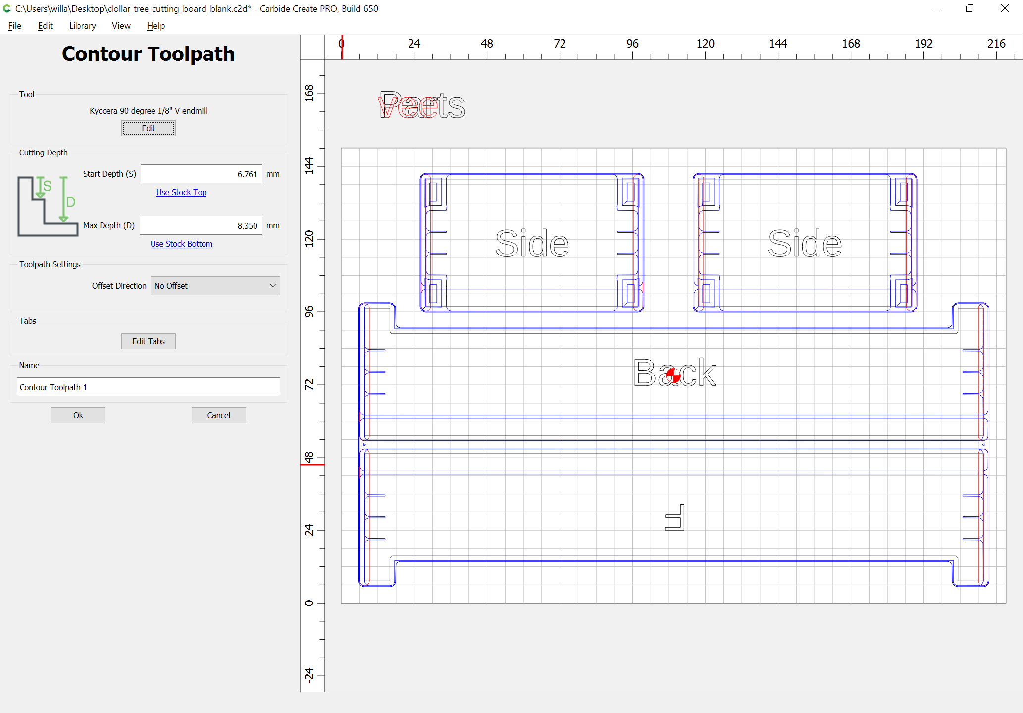
For the blind miter, rather than using a V carving, it is most expedient to use a no-offset contour toolpath applied to open geometry which precisely describes where the cut is needed, so draw in such geometry:
along the edges of the joints:
WillAdams
May 2, 2022, 3:39am
12
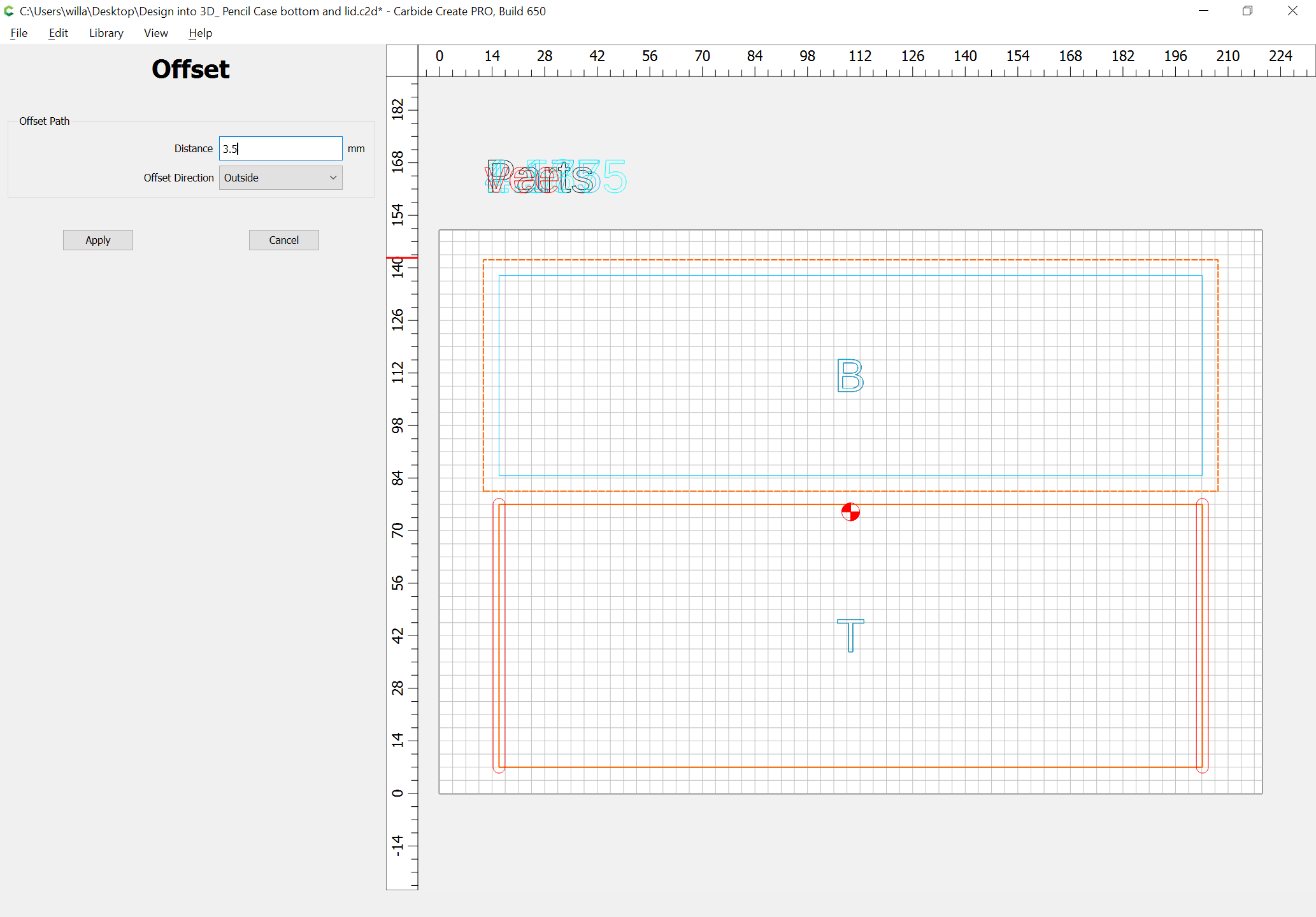
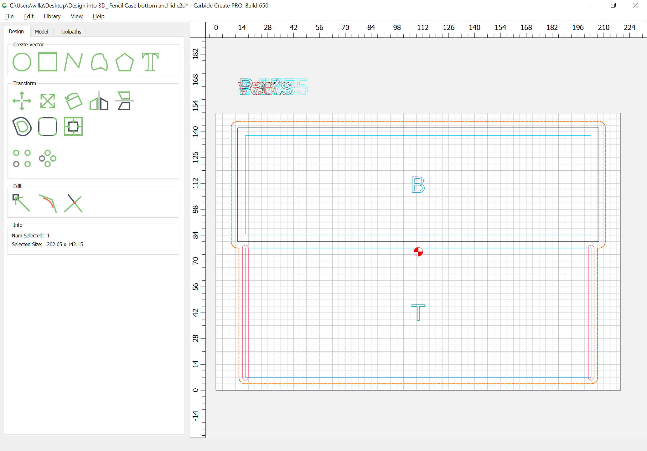
The size of this box is such that the lid and the bottom can be on the same piece of stock:
Select the part geometries and offset by endmill diameter plus 10%:
Select the geometry which will need to not be cut away, and the offset geometry, and assign a toolpath to cut as deeply as is necessary to ensure that the parts will fit into the rabbets:
Then select the offset geometry and the part geometry for the bottom and lid and assign toolpaths from that depth down to the top of the tabs:
and then select each outer part geometry and assign an outside contour toolpath which cuts from the top of the tabs down to the bottom of the stock:
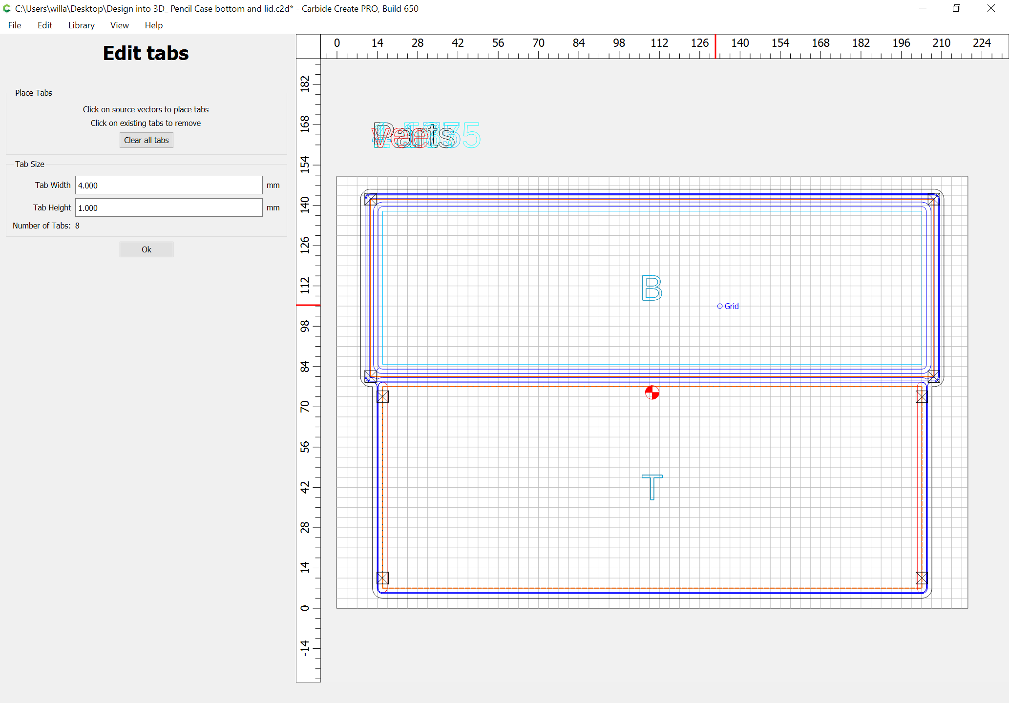
and add tabs:
WillAdams
May 2, 2022, 3:43am
13
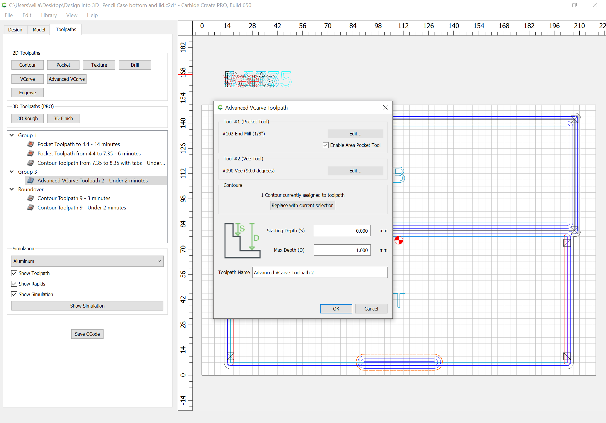
In addition to cutting to size, and cutting the rabbets for the bottom, there are three additional features which are wanted for the lid:
an advanced V carving as a relief on the underside for opening the box
a relief cut along the side edges of the lid, either a V carving, or w/ a roundover bit to make closing easier, and to match the radius of the endmill used to cut out the front/back
a relief cut along the back edge of the lid w/ a roundover bit which is sized to allow the box to open
WillAdams
May 2, 2022, 3:56am
14
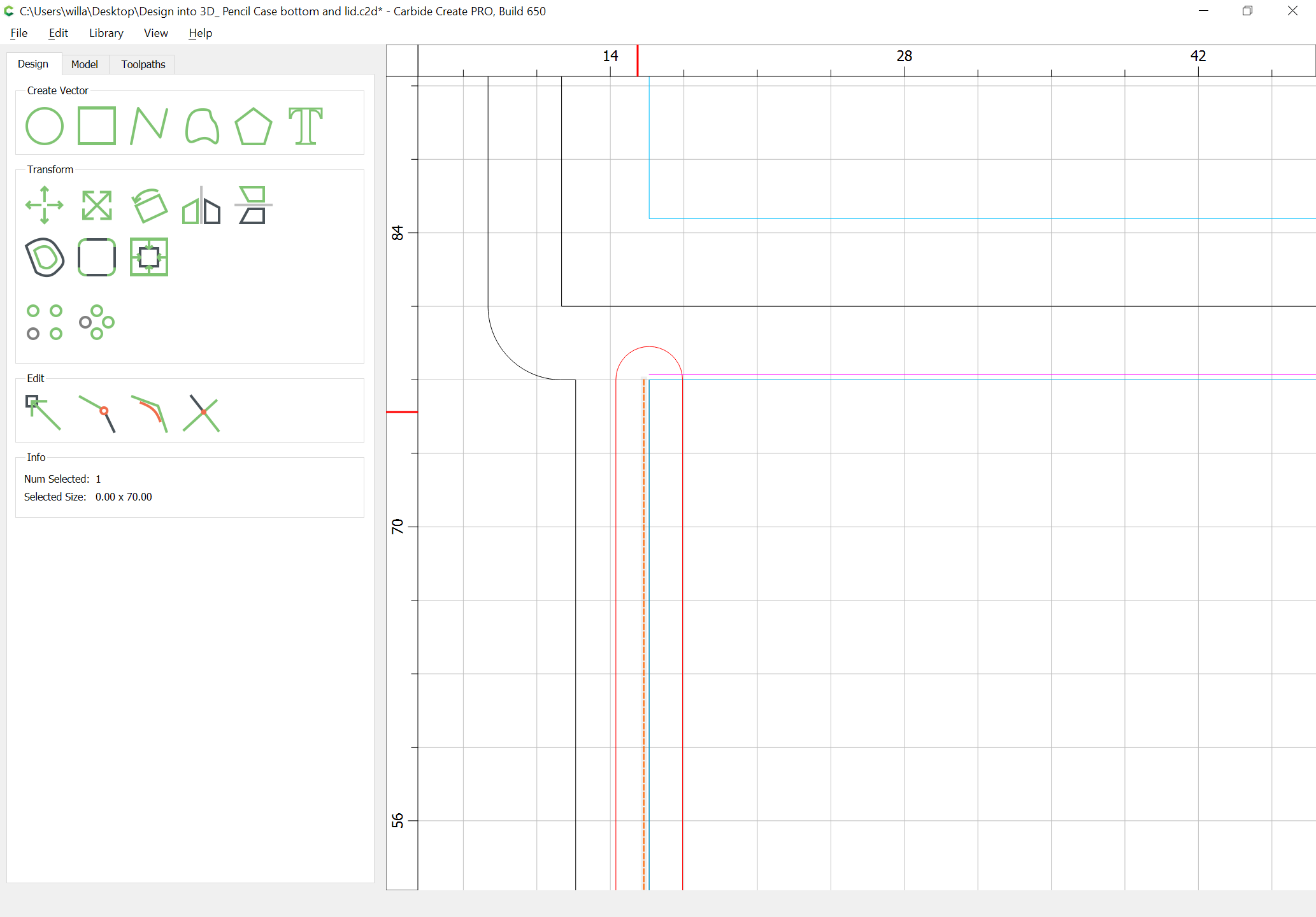
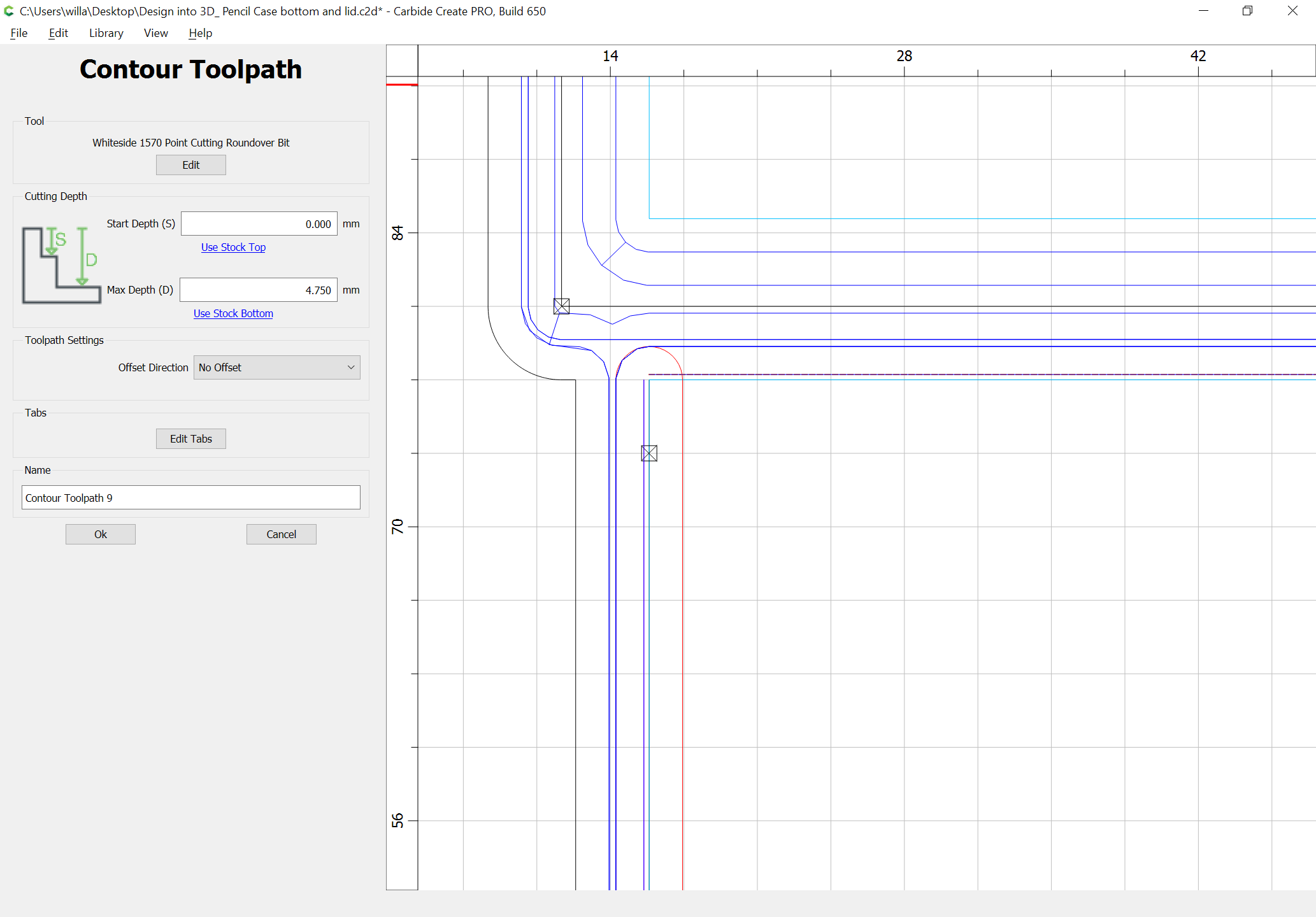
For the roundover reliefs, draw in geometry offset by the radius of the tip:
and assign toolpaths which cut as deeply as is needed for the desired roundover:
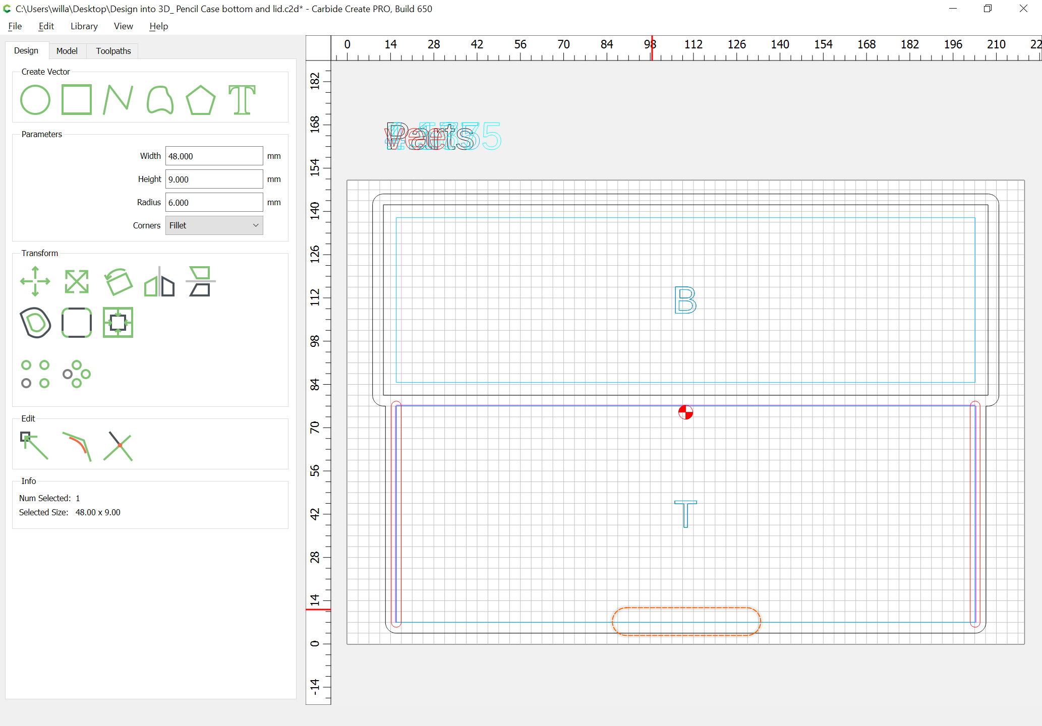
and for the opening notch, draw in suitable geometry:
and assign an Advanced V carving toolpath to the desired depth:
WillAdams
May 2, 2022, 3:57am
15
Arrange toolpath groups to match the desired cutting order:
1 Like
WillAdams
May 7, 2022, 2:45am
16
Files are at:
Design into 3D_ Pencil Case bottom and lid.c2d (742.6 KB)Design into 3D_ Pencil Case front back and sides.c2d (921.3 KB)
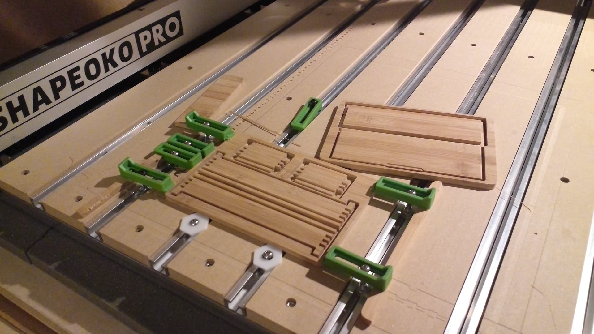
Cutting (w/ a bit of adjustment reflected in the files above) went well:
separating the parts, cleaning up the edges, and drilling for hinges, glue-up and assembly will have to wait the morrow.