Can anyone tell me if it is possible to make a climbing hold in Carbide create, or would I have to use a different program to design it?
You’re talking about the things that are stuck on rock climbing walls, right?
You’ll need to use a different program.
Carbide Create is 2D CAD/CAM. If you can draw the toolpath you want on a piece of paper, it can do it and maybe repeat it at different depths. If you can’t (which is the case for a climbing hold), you’ll need a different piece of software.
For organic shapes like this, you’ll probably want to use something like Blender or ZBrush to come up with the shape, or maybe make/obtain a physical model then scan it.
Once you have a 3D model, you’ll need a 3D CAM package to turn it into a toolpath. Fusion 360 is probably the best free option.
Alternatively, for a part like this that sees such light loads, you might be able to 3D print it. It’ll be a hell of a lot easier than machining it. Machining this with a Shapeoko or Nomad is likely to take at least two setups.
3 Likes
I didn’t know what you were referring to, but if Lucas is correct, these things come in a huge variety of shapes. Some of them don’t look very CNC friendly.
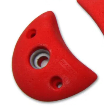
You might be able to make simple climbing holds like these in CC Pro by cutting a cylinder out of an ovular extrusion:
This individual is making some climbing holds on their Shapeoko and has some YouTube videos.

However as the others have eluded the holds this individual is making in the videos are simpler holds/shapes meaning all surfaces could be approached from the one side (ie. top view of the model). If you are looking at making some climbing holds that your fingers can wrap around the top edge then you will need to work out a strategy to be able to flip/rotate the piece to mill it from various angles/approaches (ie. top, bottom, back, front, on a 45degree, etc…). So if your going for complex shapes then you’ll definitely need a 3D CAD/CAM software such as Fusion 360 with some sort of flip/rotate jig.
So your approach would need to be along the lines used in this next video but depending on your designs you may be able to get away with simply flipping the piece front ↔ back as opposed to rotating at various angles around your part.

4 Likes
I would take the view that two-sided machining of climbing holds are a pretty good application for CNC routers. You have a one or more pretty big bolt holes to index and secure the part after all. And the precision requirements are not that exacting.
But I would think 3D printed pieces will also be plenty strong for indoor (self) use. For liability reasons I would think commercial operations would probably not use self-printed pieces.
Thanks for all the info. I saw a guy on youtube named Austin Conrad print wooden holds on his Shapeoko, but I wasn’t sure if he produced the initial files in Carbide or not. I have some holds already that i would try to model them after. It just seems that now, after hearing you, I need to get something like Fusion 360, and go from there. Thanks again
Awesome.That’s exactly like one of the shapes that I was thinking. Some holds have undercuts (which I assumed couldn’t be done on the Shapeoko), but simple ones like this would totally work, thanks.
That first video that you put up, is the exact one that made me think of that question. Do you think that that would’ve have to have been done in something like Fusion 360, or is that possible in Carbide?
*Sorry Lucas, if that’s exactly what you’ve already told me.
It might be possible with carbide create pro because that paid version will do 3D CAD/CAM. That said you can get a free hobbyist license for Fusion 360. They scale back on some functionality but everything you need for such a project is still there.
Unfortunately though, I don’t have access to a 3D printer. I just ordered the Shapeoko, and was hoping that I could do it on that. I get that it’s a machine that comes down from the top, so undercuts would be hard/impossible without jerry-rigging up some kind of doohicky. I currently make my own holds by hand, but was hoping to get a little more precision, and consistency by trying it on the Shapeoko.
That’s awesome, thanks
You say jerry-rigging, but I say fixtures and jigs are de rigueur of manufacturing. If you look in a modern manufacturing site, yes you might see 6 deg-of-freedom robotic arms, and maybe you’ll see 4, 5, or 6 axis CNC machines doing prototypes or things that can’t be done otherwise, but I’ll wager the most of the machines and operations only move in 1, 2, or 3 axis, just like our Shapeokos. Going back 100, 150 years ago, how do think they manufactured parts in bulk without CNCs? How did armories make thousands and thousands of rifles, revolvers, with their intricate lock and trigger mechanisms? The final fittings might have been been done by expert craftsmen, but the bulk of the the work was done by workers relying on jigs.
For the purposes of this discussion, the jig part can be a simple as two dowel pins.
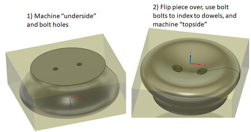
Heck, for things that are agnostic to the orientation like my model above, you can even omit the indexing part. Yeah, I understand that this may be beyond your comfort level for now. But please don’t look down at what you can do with a simple 3-axis machine.
1 Like
I’m definitely not looking down on what this machine is capable of.That wasn’t my intent at all. If anything, I was just saying that some of the jigs that I’ve seen some people make are way beyond me right now. I only ordered the machine last week, and it hasn’t been delivered yet. I’ve also never used a cnc machine before, but I am definitely up for the challenge.
That being said, that model that you did there is awesome.I didn’t think of running it through twice, once upside down, and once right side up. that would allow for many more shaping options. Thanks a lot Kelaa.
On a side note. Was that modelled in Carbide Pro, Fusion 360?
That was a quick sketch in Fusion360.
If you give the people on here a suite of chisels, planes, gouges, saws, and 100 hours to learn, practice, and make, I don’t think most of us will amount to much. If you spend 100 hours with a design software, the CNC, and even assuming all you have is wood, a few bits, and just tape for hold-downs, I think you’ll be amazed at the output.
Example of how I plan on spending Christmas break:
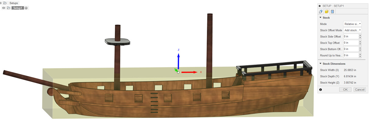
At 6.8" wide and 3.9" tall, it is too big for me to square up as one piece, so I plan on machining a block of wood as the right hull with all the features accessible from the right side, a block of wood as the left hull with all the features accessible from the left side, then gluing them together and do the final machining from the top. Nothing fancy required, other than a bit that has 3.4" reach, some double-sided tape, and careful probing.
2 Likes
That looks amazing. I would definitely love to see a pic or two of the finished product.
This topic was automatically closed after 30 days. New replies are no longer allowed.