Hi new to Carbide pro here. Trying to make a rounded 3d half section that can be flipped. I have the 3d roughing set up with an offset vector on the stl of .25. I can set up a contour on that same vector and it makes tab from the vectors i set up. But as soon as i get to the roughing its simulation shows that the 3d roughing erases my tabs on the contour pass. Anyone find a workaround yet?
Tabs are only supported for geometry and Contour toolpaths — you’ll need to set up your 3D model to leave stock uncut by 3D toolpaths which can then be cut away by a Contour toolpath to which you have added tabs.
You could either add the tabs to the 3D shape as a component…
Or you could add tabs to the boundary you are using to do the 3D rough & finish.
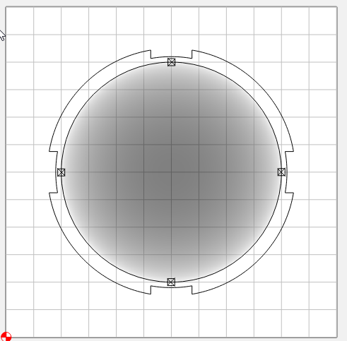
The inner vector is for the profile with tabs. The outer boundary is for the 3D paths.
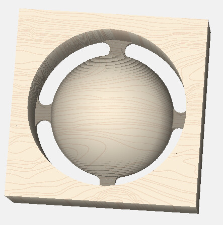
Results in…
Keep in mind the boundary for the 3D paths, the tool center will travel to the boundary, i.e. the boundary has an “ON” or “No Offset” condition
1 Like
Very Helpful! THANKS! Yeah i just added some tabs in fusion 360 to my stl and then did the same steps with making my contour pass have tabs in the same location. Not sure if the conversion that the software is doing going to greyscale is correct though because the tabs seem thicker than what I have assigned in Fusion. Anyways the contour pass gets them cut to size.
Anyway you can share the file with this solution? Would love to learn your method. Not too sure I understand it.
Sure. This actually has both solutions, the tabs modeled in 3D, and allowed for with the 3D path boundary.
ashdip_sphere_tabs.c2d (740 KB)
This topic was automatically closed after 30 days. New replies are no longer allowed.