I was wondering if anyone has had similar issues when using the IDC Woodcraft’s “Beast” roughing endmill. I use it to cut out pieces using a pocket that is sized for 10% larger than the endmill (i.e., .275") to avoid ‘slotting’.
I’m using a Shapeoko Pro 5 with a 65mm VFD spindle. The endmill’s settings that I’m currently using are:
Depth of Cut: 0.15"
Plunge Rate: 12" / minute
Feed Rate: 84" / minute
Speed: 22000 RPMs (actually closer to 20K because the VFD is always running a little slower than it’s told to).
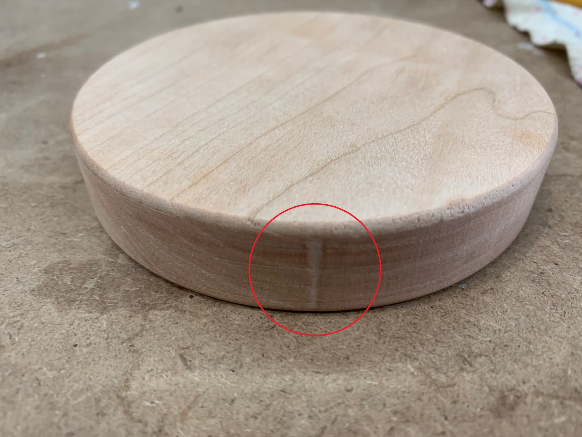
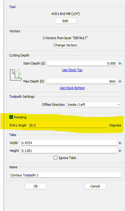
The attached image shows the vertical mark in a piece of cherry and consistently happens where the endmill plunges to change the depth of cut. I’ve tried using a 5 degree ramp but that didn’t seem to have any positive effect.
Thanks Will, that make sense. I used to use C3D’s #251 for cutouts and it didn’t have this problem but the “Beast” is so much quicker and actually leaves a decent finish with this exception.
I’m assuming there’s no way to force the pocket toolpath to do the depth change plunge on the outside of the pocket (away from the piece being cutout) rather than up against the piece.
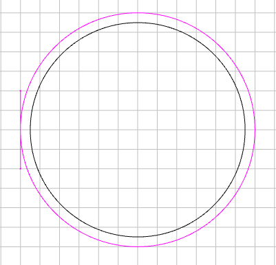
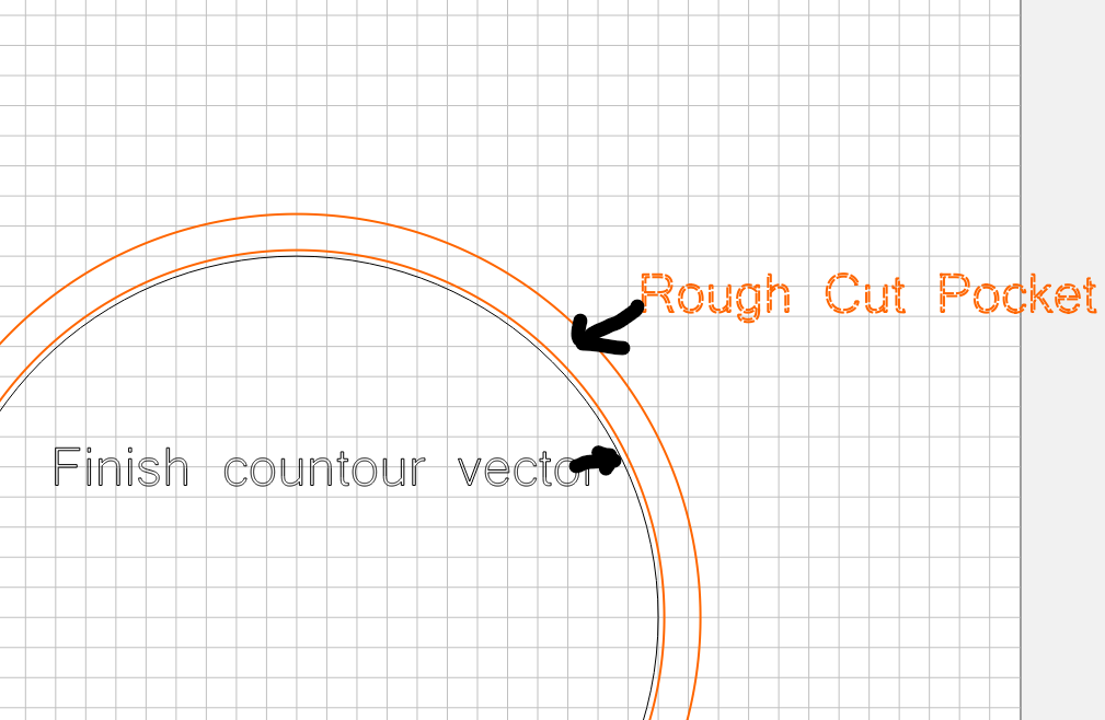
If it’s not possible in software, a “quick fix” might just be offsetting your contour by your clearance amount. Select the offset contour for your pocket operation and then come in and clean it up with a finishing operation selecting your actual to-size contour.
A little more annoying in terms of generating the tool paths but if you’re doing ~basic shapes it should be pretty straightforward.
Just an update. Unfortunately the new Cutout toolpath causes the same issue with the Beast endmill. When the endmill transitions from the outer perimeter of the toolpath to the inner perimeter (right next to the piece being cutout), it overshoots by just a bit and causes the same vertical indentation. I guess a finishing contour pass will be the way to go when using this endmill.
I think then your only recourse might be to create an offset curve, cut the vector and add lead-in & lead-out. Contour path with no offset. (again, no direction control. Although sometimes mirroring the curve changes the direction, if it’s a symmetrical curve)
The reason you are getting that little “burn” mark is that the machine is going up and down in the exact same spot. When the machine does a straight plunge in the same spot, that’s the result.
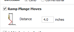
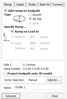
Adding a Ramp will move the plunge along the vector each time the carve plunges deeper. The longer the ramp, the less burn you will get.
Also, you can go with .25" DOC and 100 ipm with a Rough Cut bit and your machine.
I also suggest adding an offset vector for the rough cutting bit. Start with .05" and dial it in based on your needs. After you do the rough cut, use a toolpath for the finished vector and use a regular end mill. I would still include a ramp for the plunge.
Thanks for the information I did try a 5 degree ramp and it didn’t seem to help. For a roughing endmill, it does a decent job from a finishing perspective but as you and others have pointed out, it seems the way to go is to use an offset and follow that up with a finishing pass.
Thanks Gary. Not sure if the “Ramping” feature in CC Pro is similar to the lead in/out feature of Vectric but I’ve tried that. Unfortunately does it not only still leave the tool marks but it can create significant burn marks as well which are just as difficult to sand out. I’ve also tried dropping the Plunge rate but that didn’t seem to have a significant benefit either. Originally I thought that this was unique to the Beast endmill because I hadn’t thought I’d seen it on C3D’s 251 endmill but I am actually seeing the same marks with that tool as well.
I’ve been considering trying out Vectric and maybe this will be the push I need to do it.
Thanks Anthony. I haven’t pulled the trigger on Vectric yet but have been watching all the training videos. It certainly looks like it has a lot of options to offer including the more advance ramping that you’ve described. Can’t wait to try it out!
I honestly use Carbide Create more than Vectric. There are some things about Carbide Create that I prefer over Vectric and vice versa.
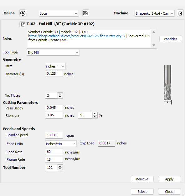
Vectric is better for Node Editing, Image Tracing, Boolean Unions, and related features. It has better tools for turning a design idea into a file; I often use Vectric to do my design, then export the SVG to CC for toolpaths and g-code. CC is easier for sending the files directly to CM and identifying tools. I.e., many tools in Vectric are Tool 1. It’s a bit cumbersome to do a multi-tool carve. Specifically, in CC, you get a prompt for a tool change with the tool number and name (i.e., brief description). In Vectric, you get the Change to tool #4 option, but then you have to go back to your design file to select the correct tool. I recently figured out a way to get Vectric to work more closely with CC on tool naming, etc
One thing about Vectric that is SUPER useful is that it lets you use more than one clearance tool in an advanced V-carve. This feature is great for inlays. Saves a TON of time.
I just went through the standard vectric Tool Database, and at least 4 tools were listed as tool number #1
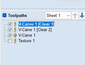
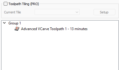
CC is great for creating toolpaths, organizing CAM orders, and directly sending to CM. It has a better UI for toolpaths (at least for me). Also, CC gives you approximate toolpaths times instantly, whereas Vectric requires you to click a separate screen.
Thanks for the comparative analysis between the C3D tools and Vectric. It looks like the post processor from @Allen44 that @CullenS suggests cleans up the issue with tool naming so I’d definitely use that. I could easily see myself thinking I remembered what “Tool x” was, being too lazy to double-check and then mess up my project with the wrong tool