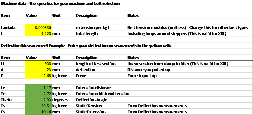
The spreadsheet
Here’s a copy until I find a sensible permanent place.Belt Tension Examples.zip (9.3 KB)
How much Tension is enough?
The minimum belt tension numbers from Gates (the main manufacturer of the GT2 and GT3 2mm belts) are way below the tensions that you end up with on the Shapeoko after tightening up the belt tensioner clips.
Motor Torque
On our machines a realistic target value for belt tension is the maximum force the stepper motor can generate (link to stepper holding thread). It’s reasonable to state that we do not want either side of the belt to go slack due to motor force trying to move an axis. This is also the maximum static force we should care about on the machine as anything larger will cause motor slip. The Gates GT2/3 belt profile is designed to provide very high forces for quite low tensions on the pulley so belt jump is unlikely to be an issue.
Motor holding force has been measured at around 18lbs f (8.2kg, 80N - same thread as before), all three of my belts with the normal tensioners and no tricks to jack up the tension have achieved well above this min tension and I am not going to try to increase them, I will equalise them instead.
Belt Limits
The Gates GT3 fiberglass core belts are specified to a breaking strain of around 850 Newtons which is likely to damage the stepper motors very quickly. There is a Gates application note which states that backlash can be reduced at high tensions
See pg 65 of;
“Higher belt installation tensions help in increasing belt tensile modulus as well as in increasing meshing interference, both reducing backlash. Tension values for these applications should be determined experimentally to confirm that desired performance characteristics have been achieved.”
Where in that range the belts cease to stretch linearly with force and backlash would be reduced with additional heaving on the tensioners I do not know, the Gates suggested starting point is well within the ‘normal’ Shapeoko tension range as measured above.
Breaking the Steppers
The other key element to consider is what the stepper motors can cope with as an axial load. The axial load on the stepper pulley will be twice the static belt tension as it sees this load on both sides.
Applied Motion rate their NEMA 23 motors for a max radial force of 62N / 13.9 lbs.
Motion Control Products rate their high torque NEMA 23 for 75N
The general range for NEMA23 appears to be sub 100N at 10mm from the mounting face, it would appear that many Shapeokos where the user has taken care to really tighten up the belts are already substantially exceeding this so the actual ratings for these steppers will make for interesting reading.
As described here
the high radial load from high static tension causes the motor shaft to flex as it rotates and this causes fatigue failure over time, overtightening is not an immediate break the motor shaft issue, it’s a long process of weakening the shaft until it fails. The same applies to the bearings, high radial loads will cause early wear-out failure.
WARNING Maths
If you want to know how the measurements are converted to tension values;
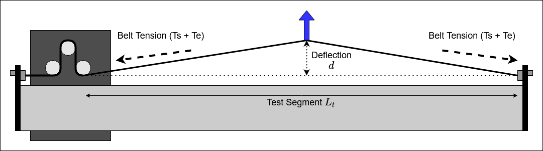
Belt Deflection Method
For the deflection measurement, when we deflect the centre of the belt we apply a Force F to create a deflection d. This increases the length of the belt by an extension length Le and therefore increases the tension from the Static Tension Ts by the additional Extension Tension Te.
The other wrinkle to deal with is that the tension increase Te depends upon the full length of the belt, including the bits around the motor pulley and trapped on the other side of the carriage so we are testing deflection across the Test Segment length Lt out of the total belt length L;
If we know the belt’s tension modulus (how much it stretches per unit tension force applied) we can now do some simple trigonometry to work out what the belt tension was before we deflected it.
First to calculate Le, the amount of extension caused by the deflection, this is simple length of the hypotenuse of our belt triangle, minus the adjacent length.
The additional tension Te caused by deflection is then the fractional extension over the belt tension modulus.
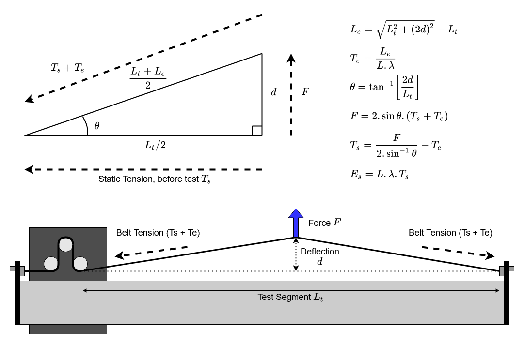
Finding the angle is a simple inverse tangent, remembering to use 2 times deflection as we have two triangles back to back.
To obtain the deflection force F we calculate the vertical component of the Ts+Te tension in the angled belt. F is given by 2 sin(theta) times the total tension (Ts + Te). Again, 2 sin because we have two triangles and belt force on both sides resisting F and pulling down.
A simple re-arrangement gives the static tension Ts in terms of our measured parameters.
Finally, we can calculate the static extension of the belt Es as the product of belt modulus, overall length and the calculated static tension. This should be how far you pulled the belt whilst doing up the tensioner bolts.
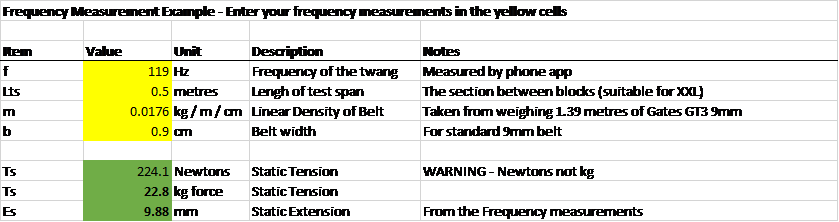
As an example;
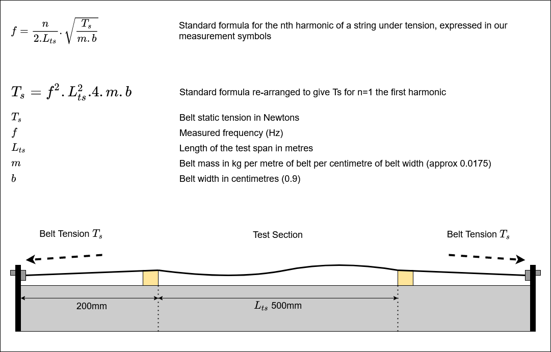
Belt Frequency Method
The belt frequency method is substantially easier to calculate as it is based on the standard formula for vibration frequencies of a string under tension, a little relabelling with our symbols and re-arrangement yields a formula for Ts for the first harmonic (fundamental) which is what the Gates app seeks to measure.