Measuring belt tension, squaring and calibration

A post about belt tension, how to measure it, what effect it has and why you need to manage belt tension in order to usefully calibrate and square the machine.

As usual, no criticism of the machine here, in fact some quite clever design choices seem to have been made.

The question of drive belt tension has been bugging me. How much you should have, how to check it and how it affects machine performance. I failed to find any quantitative data to use, so I went and started measuring; and found that belt tension is quite important if you want to square and calibrate the machine effectively.

TLDR

  • Belt tension means belt extension, if your Y belts arenā€™t equal tension your machine canā€™t be square and your Y steps per mm calibration can only be valid for one X position. You can fix this pretty easily by using the frequency tuning method, twanging the belts and tuning both Y axes to the same note.
  • The belt tensions easily achieved with the unmodified Shapeoko tensioner clips are well above the recommended shaft radial loads for a normal NEMA23 stepper. The results of persistent high radial load are fatigue failure (shaft snapping) and early bearing failure
  • Measuring belt tension is easy and you can do it with a cheap luggage scale or a free phone app
  • Checking belt tension as part of maintenance will likely warn you when the reinforcing members in belt a starting to fail

I so far have no reason to believe that increasing belt tension reduces backlash or otherwise helps the machine, at least within the linear range of tension on the belt and the radial load acceptable to the stepper motors.

I will be adding a belt twang to my regular machine checks, particularly to check the Y axes are balanced, Iā€™ll also periodically take numbers with the phone app to check if my belts are going stretchy.

I will also not attempt to square or calibrate my machine in only one position, Iā€™ll be checking back and front after balancing the Y belt tensions in future.

Hereā€™s a video showing how to do the measurements.

Also, many thanks to @Julien for his assistance, suggestions and measurements from his machine.

Measuring ā€“ Belt Deflection

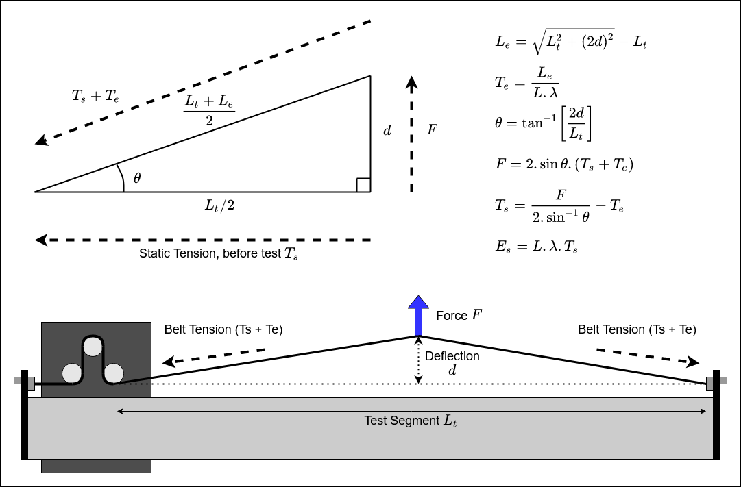
The first method is to deflect the belt in the middle of a span and measure the deflection and force required, this is how belt tension gauges work on engines for Vee belts etc.

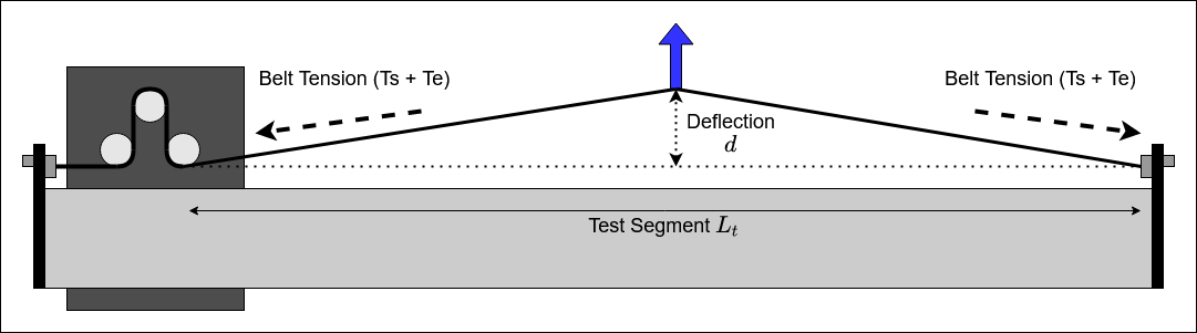
With the machine powered off push the X rail and Z carriage to their end-stops. Now mark the mid-point of the belt span between the drive pulley and tensioner , thatā€™s about 450mm on the XXL.

On that mark place a block of about 25mm (1 inch) height for a long rail on an XXL or XL, or a block of about 10mm height for the short rail variant. With the belt in the normal position, mark the top of the belt on it and then measure the distance between the mark and the top of the block, thatā€™s how far we will lift the belt from the normal position, our deflection d.

With the luggage scale looped around the belt, pull the belt up until the top of the belt is flush with the top of the block, a finger is sufficient to test this, and record the measured ā€œweightā€ as our measure for the Deflection Force F.

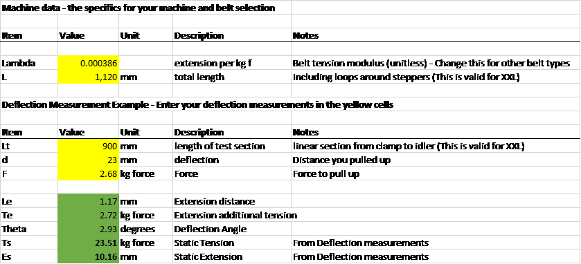
Knowing the tension modulus of the belt from the vendor data (Gates) or measurements of the specific belt (thanks to the_real_janderson see thread) we can then stick these numbers into a simple spreadsheet and get the belt static tension on our machine.

Measuring ā€“ Belt Tone

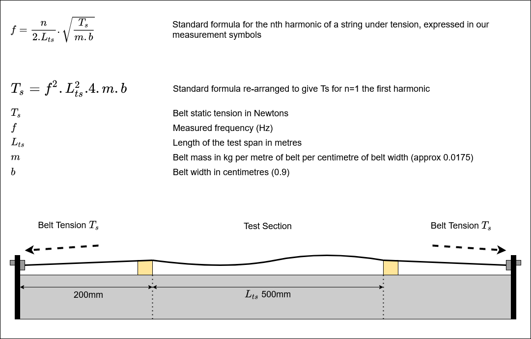
The much easier way to measure tension on the belt is to twang it and measure the frequency of the twang. For this Iā€™m using the Gates Carbon Drive belt tension app for bikes. Itā€™s free and measures in about the right range.

To measure the tension using the belt tone method we need to have a known length of belt that we can produce a clean tone from when twanged. To do this;

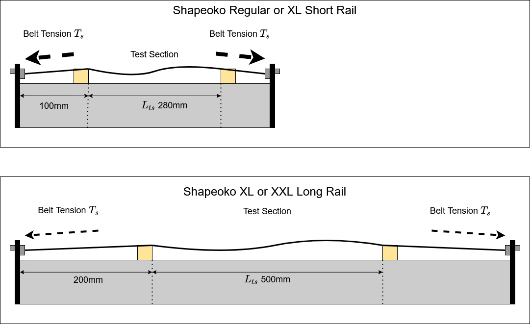
Measure and mark a suitable length on your Aluminium extrusion rail, Iā€™m starting 200mm from the end-plate and using 500mm length, 280mm seems a good number for the shorter rails of a regular or XL machine.
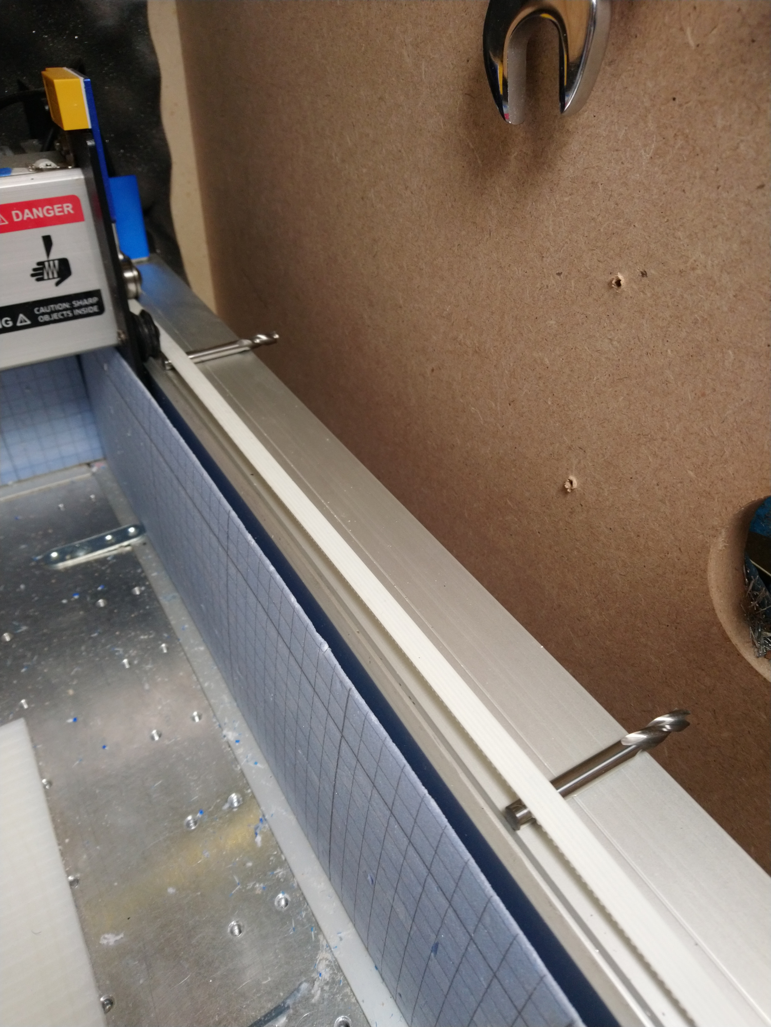
Stick a small block or a Ā¼ inch cutter shank (thanks Julien) under the belt at each side of your marks, ensure you get the correct sides and that the distance of un-supported belt between the blocks is what you measured.

Now twang the belt, you should get a pretty clear tone without the slap of belt on rail or too much buzzing.

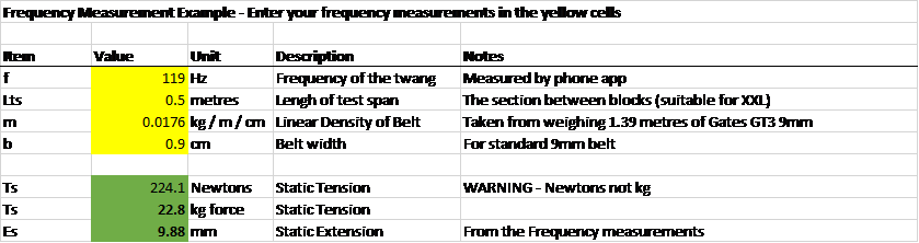
The Gates app is meant to be used for lower frequencies on bicycle drive belts, it seems to get confused once itā€™s been open for a while so I close it and re-open it for each measurement. Put the phone mic close to the belt and twang. Youā€™ll get a series of samples where the app is ā€œtriggeredā€ by the twang and a frequency reported figure out a reasonable average for the ā€˜goodā€™ samples. Repeat for each belt.

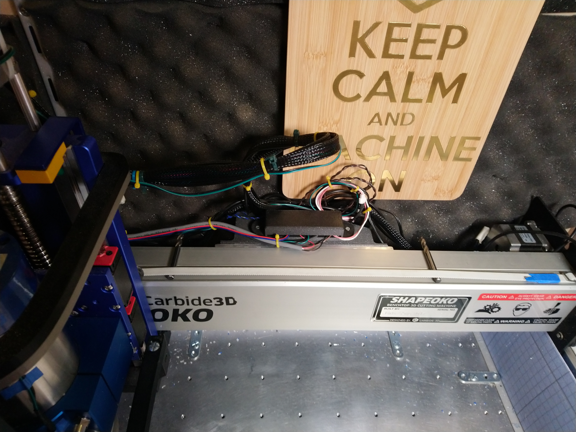
Shapeoko, XL and XXL

So far, everything here has been about my XXL machine, how do the numbers compare for a regular sized Shapeoko or the short Y axes on an XL?

I had expected the short rails to show about twice the tension of the long rails as the tensioners have the same length bolts, this does not seem to be the case. It appears that the belt slip on the tensioner as you tighten the bolt works to regulate the tension into the target range pretty well.

This appears to be key ā€“ the belt tensioner is trying to stop you breaking the stepper motors.

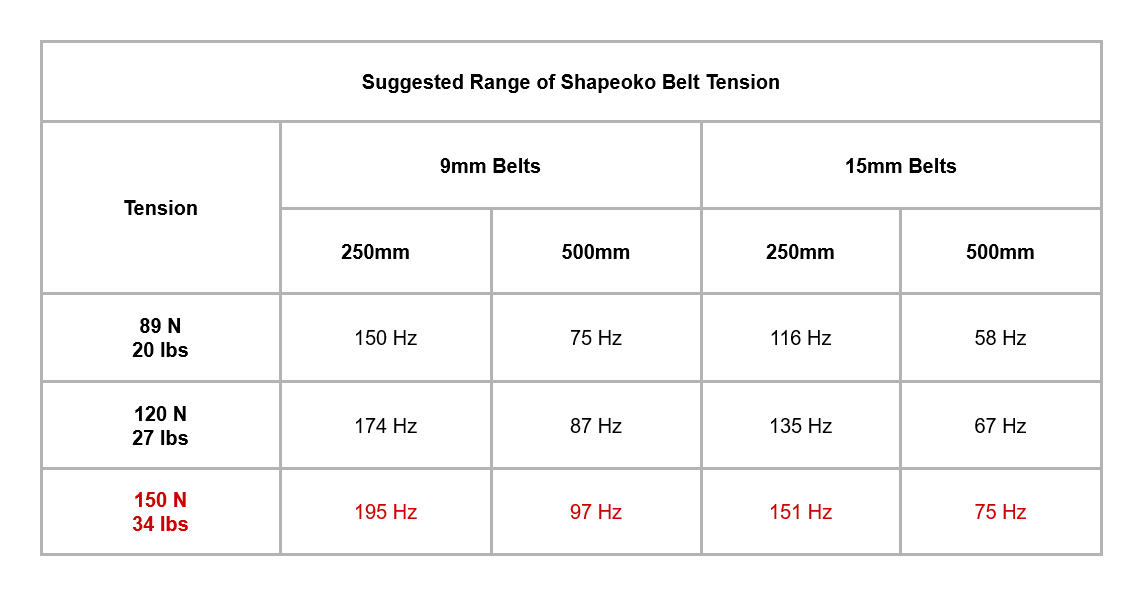
The next questions are along the lines of ā€œWhat frequency and distance should I get on my machine?ā€

Julien has tested at 275mm on his machine, 280mm is very nearly 11 inches soā€¦

Squaring & Calibrating

So, what about squaring and calibrating?

If you want square joints and parts, itā€™s key to get the base of the machine and the Y rails level and square. Itā€™s also important to ensure that the X rail is square between the two Y rails. On mine I had to shim the X rail to get it reasonably close to square.

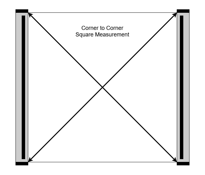
Typical measurements are

  • Corner to corner and the Y endplate to Rail support plate distances to ensure the base is square
  • That the X axis is square to the Y rail plates and Y rails.

Getting this basic geometry right is key to getting square parts from any machine.

Shapeoko Y Homing Distance Measurement

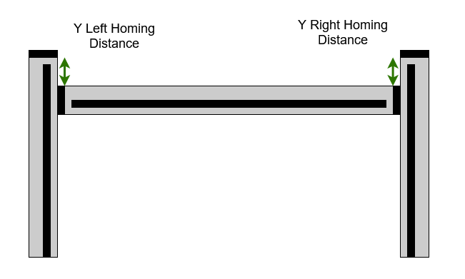
The problem is that we tension the Y drive belts by stretching them, this changes the tooth pitch of the belt which is what we base the GRBL $100 and $101 parameters on, 40 steps per mm. When the Shapeoko starts up it runs to the back of the Y rails to the homing switch on the right hand rail, assumes that the Y homing distance is good left and right and then takes steps forward from there on both Y motors, assuming that both Y have the same step distance.
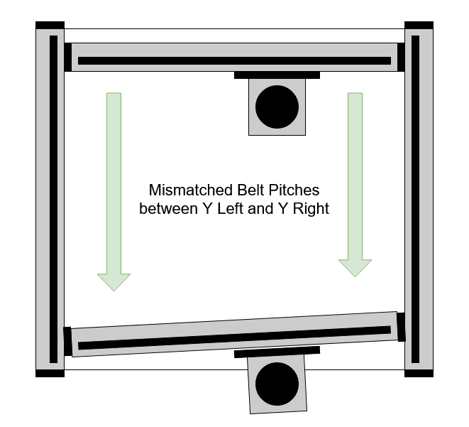
If these two belts donā€™t have the same tension, assuming theyā€™re from the same batch and not worn out, they wonā€™t have the same pitch either, meaning that by the time your machine gets to the front, the X axis is misaligned. Also, your Y distances will depend on whether the Z carriage is further Left or Right. This is a bit of a problem if you want accurate or square parts, particularly if youā€™re using something like a vertical front mount for cutting dovetails.

(again, thanks to the measurements in this thread for the belt tension modulus data)

Taking all the values for my machine I checked this out to see how badly off I was.

My left and right Y axes were;

Those values seem reasonable given the available tensioning adjustment screw length.

If the numbers are correct then Iā€™m 0.7mm off square just by jogging to the front of the machine, which makes a bit of a mockery of carefully shimming the X rail to be square with the Y plates (and also explains why when I use the edge finder on my framing square clamped to the spoil-board itā€™s not squareā€¦).

So, I measured the gaps between the Y carriage plate and the vertical steel Y rail supports at the back when homing and jogged all the way forward. Note that this measurement assumes that the Y end plates and Y rails have matching dimensions left to right;
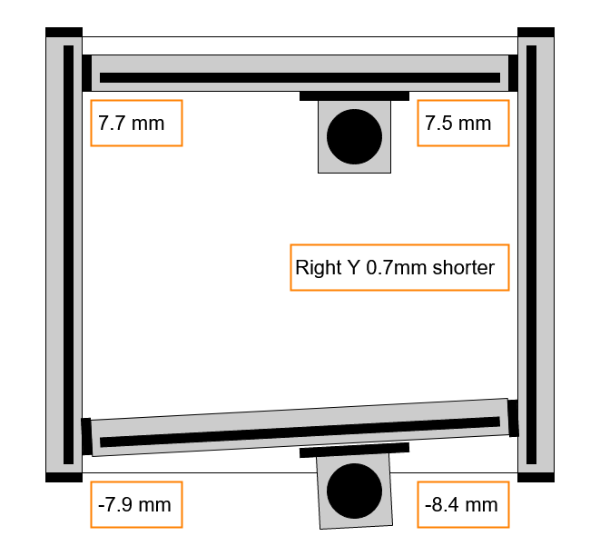
Thatā€™s a bit of a coincidence, 0.7 mm out of square by the time I get to the front, for a very small tension difference of only 3Hz, thatā€™s from B2 to B2 flat.

I equalised the tones by releasing some tension from the left Y rail and re-measured, I now have 0.3mm offset at the front which is close enough without some much more detailed measurements.

Next up - How much is too much? and Math(s)

39 Likes

Excellent Stuff!
I think it would be great to have this integrated into @Julien 's e-book if possibleā€¦

4 Likes

The spreadsheet

Hereā€™s a copy until I find a sensible permanent place.Belt Tension Examples.zip (9.3 KB)

How much Tension is enough?

The minimum belt tension numbers from Gates (the main manufacturer of the GT2 and GT3 2mm belts) are way below the tensions that you end up with on the Shapeoko after tightening up the belt tensioner clips.

Motor Torque

On our machines a realistic target value for belt tension is the maximum force the stepper motor can generate (link to stepper holding thread). Itā€™s reasonable to state that we do not want either side of the belt to go slack due to motor force trying to move an axis. This is also the maximum static force we should care about on the machine as anything larger will cause motor slip. The Gates GT2/3 belt profile is designed to provide very high forces for quite low tensions on the pulley so belt jump is unlikely to be an issue.

Motor holding force has been measured at around 18lbs f (8.2kg, 80N - same thread as before), all three of my belts with the normal tensioners and no tricks to jack up the tension have achieved well above this min tension and I am not going to try to increase them, I will equalise them instead.

Belt Limits

The Gates GT3 fiberglass core belts are specified to a breaking strain of around 850 Newtons which is likely to damage the stepper motors very quickly. There is a Gates application note which states that backlash can be reduced at high tensions

See pg 65 of;

ā€œHigher belt installation tensions help in increasing belt tensile modulus as well as in increasing meshing interference, both reducing backlash. Tension values for these applications should be determined experimentally to confirm that desired performance characteristics have been achieved.ā€

Where in that range the belts cease to stretch linearly with force and backlash would be reduced with additional heaving on the tensioners I do not know, the Gates suggested starting point is well within the ā€˜normalā€™ Shapeoko tension range as measured above.

Breaking the Steppers

The other key element to consider is what the stepper motors can cope with as an axial load. The axial load on the stepper pulley will be twice the static belt tension as it sees this load on both sides.

Applied Motion rate their NEMA 23 motors for a max radial force of 62N / 13.9 lbs.

Motion Control Products rate their high torque NEMA 23 for 75N

The general range for NEMA23 appears to be sub 100N at 10mm from the mounting face, it would appear that many Shapeokos where the user has taken care to really tighten up the belts are already substantially exceeding this so the actual ratings for these steppers will make for interesting reading.

As described here

the high radial load from high static tension causes the motor shaft to flex as it rotates and this causes fatigue failure over time, overtightening is not an immediate break the motor shaft issue, itā€™s a long process of weakening the shaft until it fails. The same applies to the bearings, high radial loads will cause early wear-out failure.

WARNING Maths

If you want to know how the measurements are converted to tension values;

Belt Deflection Method

For the deflection measurement, when we deflect the centre of the belt we apply a Force F to create a deflection d. This increases the length of the belt by an extension length Le and therefore increases the tension from the Static Tension Ts by the additional Extension Tension Te.

The other wrinkle to deal with is that the tension increase Te depends upon the full length of the belt, including the bits around the motor pulley and trapped on the other side of the carriage so we are testing deflection across the Test Segment length Lt out of the total belt length L;

If we know the beltā€™s tension modulus (how much it stretches per unit tension force applied) we can now do some simple trigonometry to work out what the belt tension was before we deflected it.

First to calculate Le, the amount of extension caused by the deflection, this is simple length of the hypotenuse of our belt triangle, minus the adjacent length.

The additional tension Te caused by deflection is then the fractional extension over the belt tension modulus.

Finding the angle is a simple inverse tangent, remembering to use 2 times deflection as we have two triangles back to back.

To obtain the deflection force F we calculate the vertical component of the Ts+Te tension in the angled belt. F is given by 2 sin(theta) times the total tension (Ts + Te). Again, 2 sin because we have two triangles and belt force on both sides resisting F and pulling down.

A simple re-arrangement gives the static tension Ts in terms of our measured parameters.

Finally, we can calculate the static extension of the belt Es as the product of belt modulus, overall length and the calculated static tension. This should be how far you pulled the belt whilst doing up the tensioner bolts.

As an example;

Belt Frequency Method

The belt frequency method is substantially easier to calculate as it is based on the standard formula for vibration frequencies of a string under tension, a little relabelling with our symbols and re-arrangement yields a formula for Ts for the first harmonic (fundamental) which is what the Gates app seeks to measure.

13 Likes

Thanks,

Odd you should mention that, there may already be a zipfile of the notes and diagrams for Julien :wink:

4 Likes

This will most definitely go in the next version of the ebook. The ā€œmeasuring the frequency with a phone appā€ had been mentioned before, but for some reason it never resonated with me (ha-ha). But after doing a few trial measurements for Liam, I must say it does not get any easier than this. Slip two cutter shanks under the belt, measure (or set) the distance between them, launch the phone app, grab a few samples, adjust tension to reach the frequency sweet spot, repeat for the other two belts, done.
I had also never seen the impacts of uneven belt tension been explained so clearly, it was an eye opener for me as to the importance to get this right (I used to do it ā€œby feelā€) when entering the realm of dimensional precision.

Awesome post :+1: :sunglasses:

9 Likes

Fantastic information. For referenceā€¦ I have a XL machine with the Carbide3D supplied steel belts. The 500 mm X was at 74 hz and the left Y at 280 mm was 114 hz and the right Y was at 125 hz. Iā€™ve added a little more tension to the left and now both are really close. I had just gone thru Winstonā€™s tramming and squaring guidelines and I had readjusted all of my belt tensions to what I thought was correct. Now I think itā€™s even better.

This should definitely get into the A to Z guide and/or the Wiki. What is a good belt tension has been a mystery to me until now.

5 Likes

Great,

Thanks for posting your numbers, itā€™s really interesting to see what actual tension numbers other people have.

If more people want to test and post their data Iā€™ll collect it up and chart it so we can all see the ranges.

3 Likes

I have a sonic tension meter from gates that I use for checking my 3d printer belt. You can find them used cheap on ebay sometimes.

2 Likes

I had a go at retensioning my three belts using @LiamNā€™s method, and went for a target of 125Hz, which on my SO3 seems to be the sweet spot (it will be interesting to hear what value others end up using)

280mm span on the right Y belt, using two #201 endmill shafts:

280mm span on the X belt:

280mm span on the left Y belt:

What I found out today while doing this:

  • Previously, to tighten my belts I used to choose a given length of belt loop locking onto itself when the tensioner is fully tight against the plate, and then add or remove one teeth or two from the loop and re-tighten to adjust tension and have them ā€œguitar string tightā€.
  • I found out that one teeth can make a significant difference in tension using that method, and it did not allow me to reach exactly 125Hz (say, one measurement was at 110Hz, and just one teeth tighter got me 140Hz)
  • So I went for finding the loop length that gave me a value above 125Hz when fully tightened against the plate, and then slightly turned the bolt counterclockwise while measuring with the phone app, until I was at exactly 125Hz (+/-1 Hz). It takes very little untightening of the bolt, so I doubt to the bolt will go loose, time will tell.
  • after I tuned both my Y belts to 125Hz, I did the ā€œhome then manually jog to the front plateā€ test, and I now have my Y rails contacting the front plate at (almost) the same time, but more importantly with the exact same offset as the one I get when moving the gantry manually with the machine powered off (which means that the belt stretch is even on the left and right sides, and does not introduce additional shift). I still have a 0.5mm gap on the left side when the right Y plate is touching the front plate, but I chose to live with this tiny offset from perfectly square last time I shimmed my gantry (and 0.5mm over the Y travel is not much, Iā€™m not even sure what the tolerances on the Y plates and their powder coating areā€¦)

Thanks again @LiamN for opening the path to a much more reliable way to adjust belt tension, while keeping it very simple (it takes about a minute to grab two endmills and a phone to do the test).

10 Likes

Excellent work and write-up.
This thread is an instant bookmark for sure.

3 Likes

How does that tension check after you remove the blocks or bits that you use to raise the belt with?

1 Like

Good question, that depends on the size of the blocks or bits and the length of the rail but it should be a reasonably small change in tension as you remove the blocks / bits. The smaller the block the better, all we need is to raise the belt far enough to provide a constrained length of belt which can freely twang without hitting the aluminium.

This is definitely a case of the observer effect, the act of observation very definitely changes the tension somewhat.

Assuming a short Shapeoko rail and 1/4" bits 280mm apart and equally spaced between the end-plate and the carriage itā€™s around 0.25mm additional extension. At the tensions weā€™re seeing the static extension is 1.5 to 2.5 mm (depends on the belt too) on a short rail. So that suggests that the measurement is adding between 10% and 17% extra tension. Itā€™s considerably less on the longer rails of the XL and XXL.

The important thing is to make sure you do the two Y rails symmetrically (same distance from the end plate) so that you get the same additional extension & tension over the static extension and tension on the machine. That way when you balance the Y belts to be even, theyā€™re even with and without the blocks in place and you get the same steps / mm on both axes.

Does that answer the question or did I miss the point?

5 Likes

Thank you for this WONDERFUL post. I spent 30 minutes retightening all my belts this morning, feel a lot better knowing there is some science and calculations behind my belt setup now.

For anyone else following down this path, here some additional info I found.

The iPhone App

On my older iPhone SE, the measurements were (occasionally) all over the place. I kept at it until I got 4 or 5 nearly identical measurements. I also found that where I positioned the phone (in reference to the phoneā€™s microphone) effected the results. So be consistent.

I initially was strumming the belt with my thumb. Then discovered I got more consistent readings if I used two fingers to actually lift the belt and then let go.

4 Likes

This has been an interesting journey that I apparently took in the wrong direction.

  1. measured and squared the Shapeoko
  2. aligned the spindle
  3. made my wasteboard (not knowing about $100, $101 settings)
  4. Learned about measuring and changing $100 and $101 values
  5. Burdened with the knowledge that my wasteboard was not really a 1.5" grid (based off my $100 and $101 recalibration) even though holding a ruler up to it I could not tell.
  6. Followed @LiamN advice on this post and properly tightened by belts.
  7. Went back to step 1 (it was still square).
  8. Skipped to step 4, reset $100 and $101 to 40 and remeasured. Calculated 39.996 for X and a number even closer to 40 for Y.
  9. Reset my $100 and $101 values back to the factory default of 40, and had a good laugh at my journey.

I really do appreciate all the knowledge you guys share on this forum. I took a very clumsy path but I like where I ended up and could not have figured this out on my own.

8 Likes

Well on the upside, you were never very far from the finishing line and you probably learned a whole lot about your machine on the way :wink:

3 Likes

And 119 Hz - 224N is good?

Yep, thatā€™s my concern, but I donā€™t have enough data yet to really say anything about it.

I donā€™t have access to the specs for the steppers on the Shapeoko and I donā€™t know whether they were specifically selected for high shaft radial loads or not. I suspect not as typically a stepper rated for high radial load would have a larger (say 8mm) shaft and bearings, but Iā€™m not a metallurgist soā€¦

OTOH, the ratings I was able to find were for industrial quality steppers and therefore intended for motors with much higher duty cycles than an ā€˜averageā€™ Shapeoko and so our machines are likely to see a longer elapsed time to failure just because they donā€™t work 8 / 24 hours a day, every day. Also, those ratings will be based on a minimum performance for the motors, not an expected average unit performance.

Like I mentioned above I currently see no reason why increased belt tension helps with backlash and it seems that the belt slippage in the clip may well be deliberate design intent to keep us at sensible tensions for the machine.

They used to use Wantai sourced steppers+motors. The technical data should not be difficult to find, iā€™ve got the data on the BLDC motors for the nomad (but never bothered with the steppers). I suggest a quick email to them - they seem to be friendly enough to supplying data. http://www.wantmotor.com

(The nomad was shipping with the Wantai 42BLF for the spindle)

1 Like

I for one could use some more talk about how you get consistent tension with the clips. The belt almost always slips a couple of teeth when tightening. The clips donā€™t put enough downward force on the belt to hold the teeth together until itā€™s almost fully tightened, and finger strength down on the belt while also trying to bring it in range of the bolt isnā€™t the best either.

I honestly think the belt system is the next big thing due for an upgrade on the machine now that the old belt Z-Axis is gone. Itā€™s easily the source of the most deflection in the entire build, the gears on both Y axis motors effectively extend the shaft increasing the stress on the shaft even further, and setting belt tension is error prone. Half the time when youā€™re trying to tension the belt, the clip with slip down a couple teeth and youā€™ll be left with a loose belt.

Since I got the machine late last year Iā€™ve had the original belt Z axis slip so much I had to upgrade, then I had both Y motor shafts snap from a combination of tension and a sudden stop, and most recently I noticed my Y accuracy had deteriorated and tearing things down found the Y belts had started failing. In 8 months every problem Iā€™ve encountered with the shapeoko has been linked to belts.

3 Likes

I think @Julien uses blue tape to help get the belt position in the clip consistent.

However, I donā€™t think you need very much tension in the Shapeoko belts, certainly no more than the holding force of the steppers - 60N, or less, thatā€™s breakaway torque, not actual usable during motion torque.

My motivation in trying to measure the tension quantitatively was to figure out what sort of forces we were actually achieving and running at so that we could;

  • Set the tension to a known value
  • Check if these values are ā€œreasonableā€ compared to other machines, the Gates spec book, stepper motor specs etc.
  • Be able to go back and test if it had changed due to belt wear, stretch or some other effect.

I only realised part way through as I did the math(s) that matching Y tensions was important for squaring & calibration.

It currently seems to me that the slipping of the belt clips may well be either smart design of happy accident and that slippage is there to avoid us cranking the belt tensions up to the point where we fatigue the stepper shafts and break stuff. Iā€™m considering going back to mine and backing off the tension, when Iā€™ve done a few more measurements.

I have found, since measuring the tension with my phone that I can get a couple of teeth worth of extension in the clip with finger pressure holding the clip down, if it jumps before the clip gets cammed down by the bolt Iā€™m probably over-tightening it.

I agree with you that the belts are a pain, but theyā€™re much cheaper than ballscrews (which need more motor torque and therefore bigger stepper drivers in the controller etc. etc. ), theyā€™re at least the equal of a leadscrew for backlash, on the regular size Shapeoko probably better and their material is actually pretty good at vibration damping, this is all by design at Gates who designed the GT2 & GT3 belt profiles.

Thatā€™s not to say Iā€™m not trying to work out ways to improve them but I think Iā€™ll be focusing my dial gauge on the X rail to Z carriage V wheels first as many others have before me (thanks for posting the CAD Dan).

2 Likes