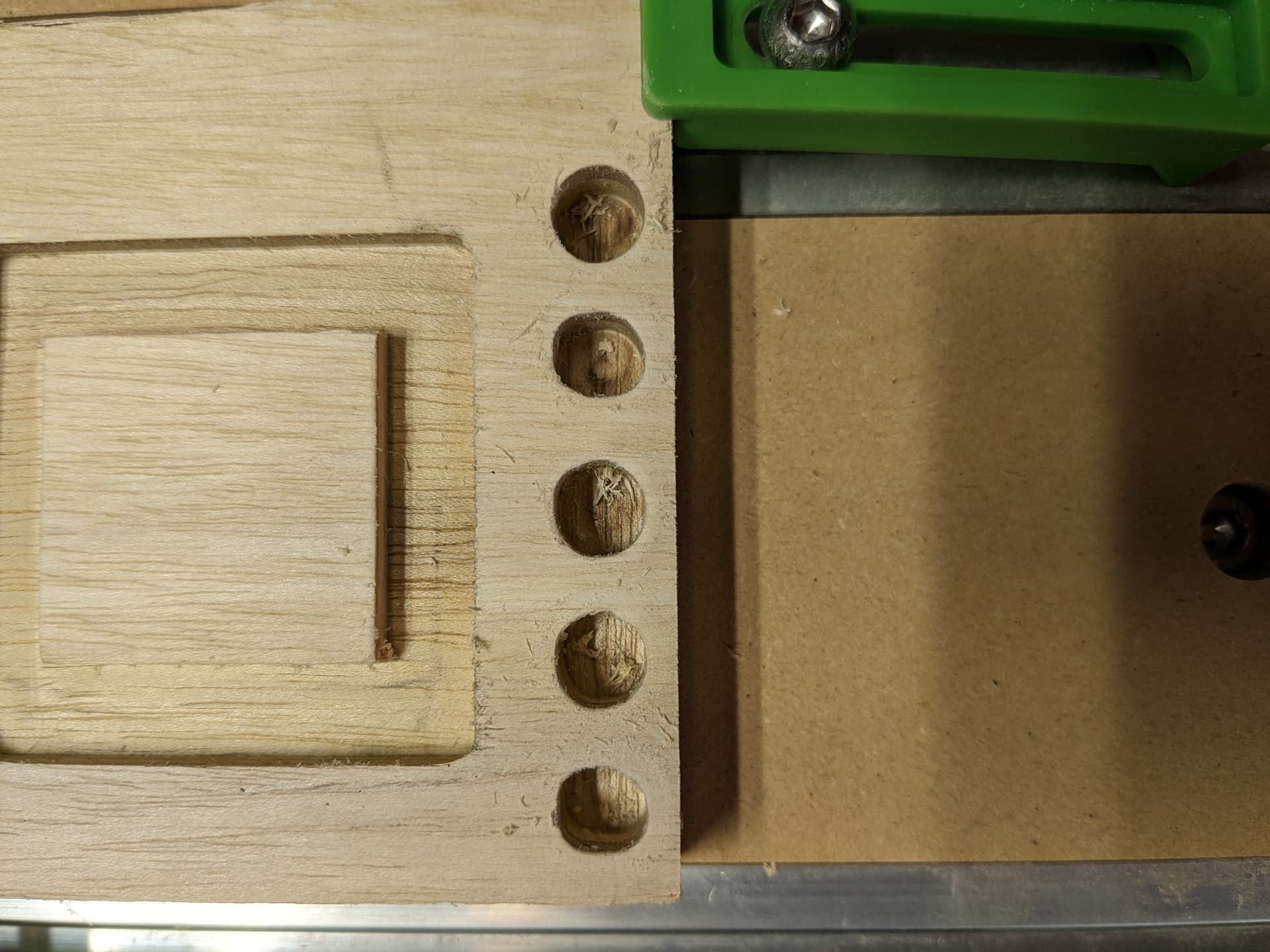
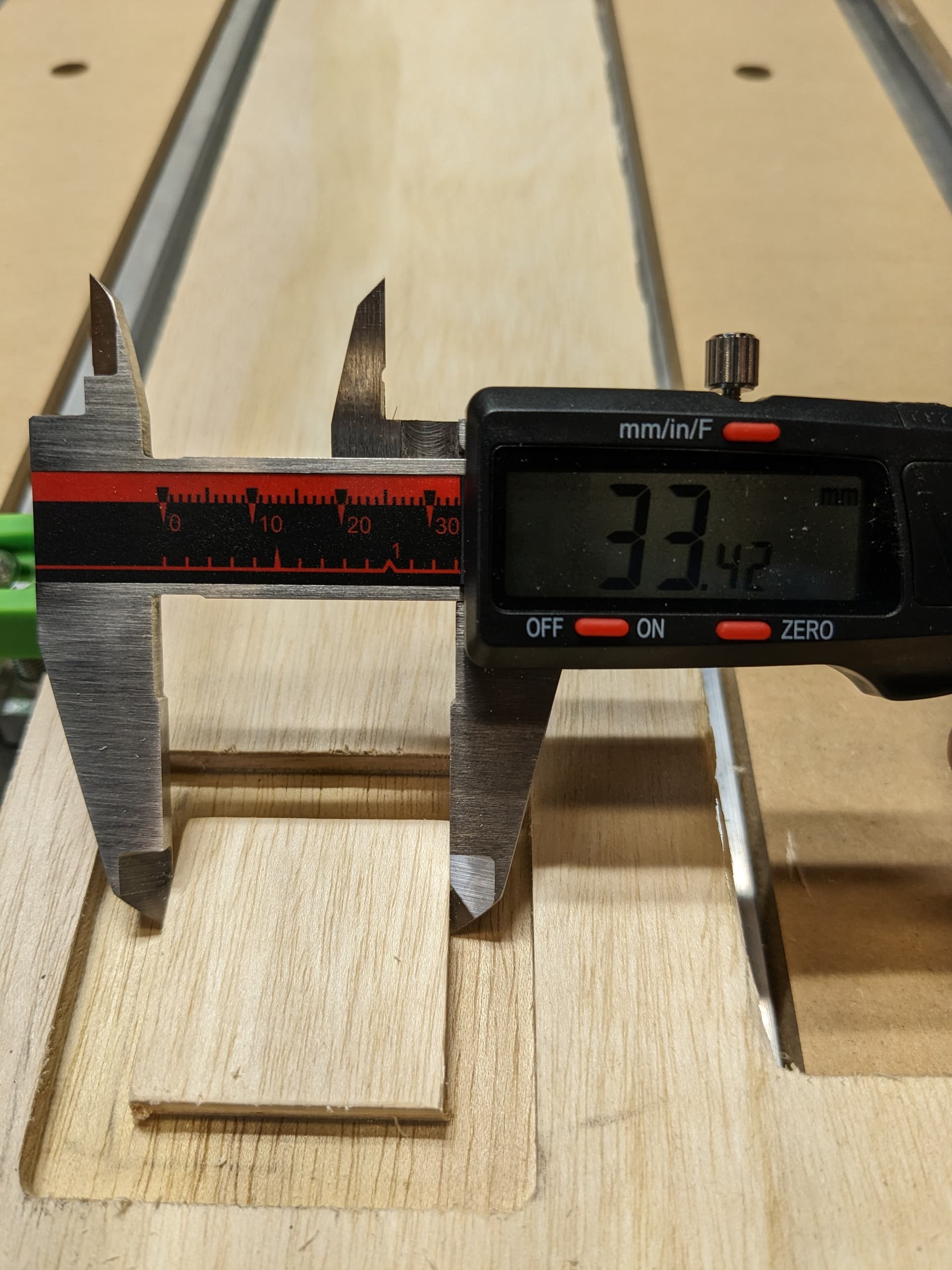
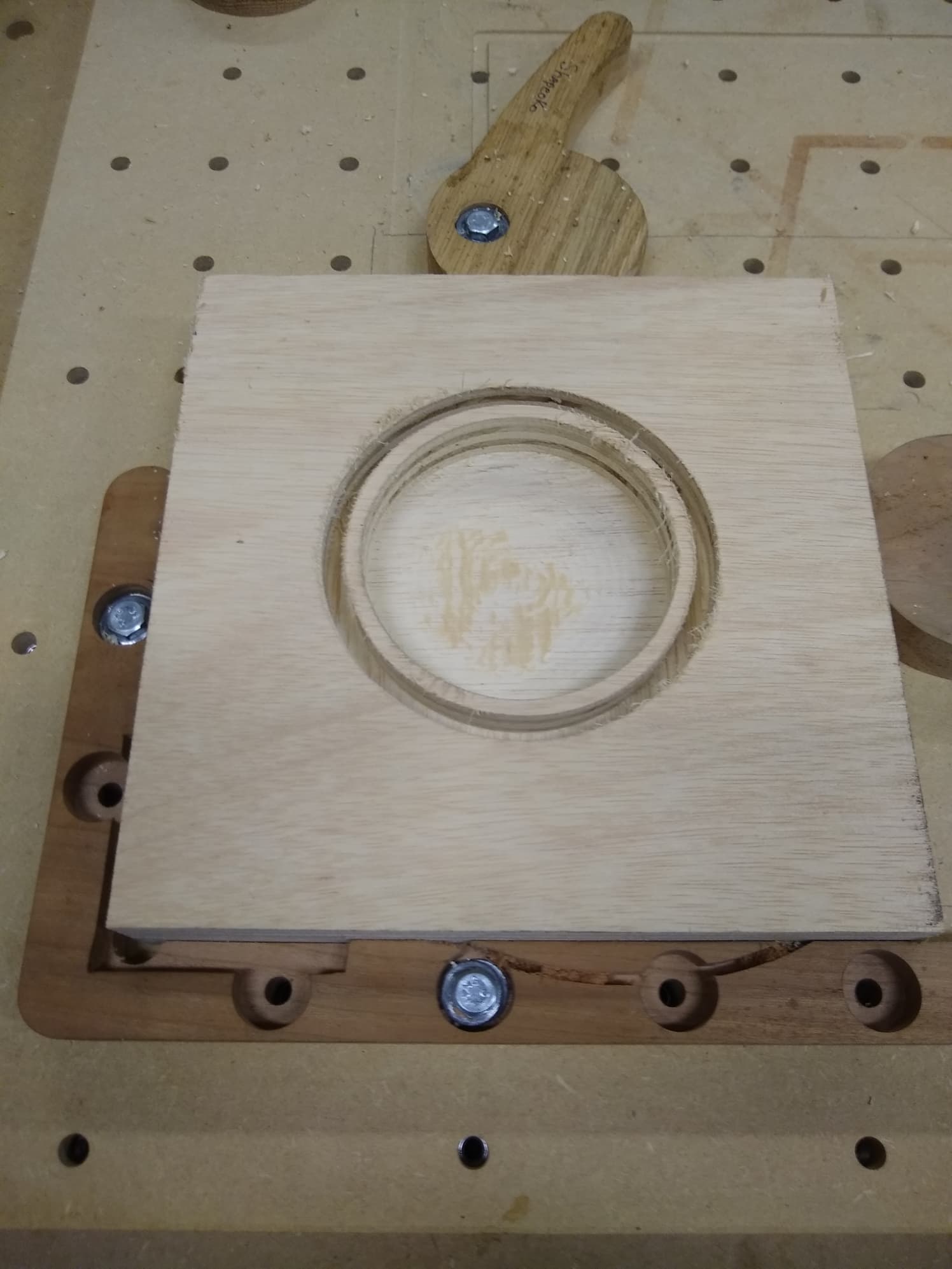
I’m very new to CNCs (much more familiar with laser cutters), but recently got the Shapeoko 5 pro 4x4. I just tried to drill out some dowel holes for for some 3/8" metal dowels, and ran into a bunch of issues with accuracy. I cleared out 5 holes in some plywood starting at 9.525mm and stepping up ~0.1mm each time, and milled out a 35mm x 35mm square. The dowel holes are pretty far from circular and are smaller than they should be by varying amounts given they aren’t perfect circles, and the 35mm square is ~34.5mm x 33.4mm, which seems pretty bad. All of the CAD/CAM was done in Fusion 360.
I pinged Carbide support but wanted to check here in case anyone has a quick idea. I’m including some pictures as well as the gcode if helpful. Chances are this is user error, so hoping it’s a quick/easy fix. Thanks!
I’m using the 1/4" flat endmill that came with the Shapeoko. I have the spindle speed set at 18,000 rpm (dial @ 3), cutting feedrate at 1524mm/min so feed per tooth is ~0.028mm. I originally bored out the holes but got the issue with circles not being very… cylindrical so I just did 2d pocket clearing on everything.
Let me know if above isn’t comprehensive enough, still getting used to terminology / etc.
Mechanical issues. Mechanical issues would be 2nd behind speeds and feeds. Since the SO5 is a ball screw machine it is harder to move the machine in any direction with the power off. However check to see if you find any rough spots and fix those. Sometimes loose screws or the linear bearings can be loose or not secured properly. This is likely an X issue. Also possible is a loose wire in the cable harness. However if they holes are consistently out of round it is likely a mechanical issue rather than a wiring issue.
The machine may need to be calibrated. That is cutting defined objects with defined measurements, then measure them and if necessary adjust the stepper motor steps. This is only if mechanical and wiring problems have been eliminated and the problem is consistent. If the problem is inconsistent the calibration is likely not the issue. Only change the calibration if the problem is consistent by cutting in different parts of the table. Otherwise check items 1 and 2 first.
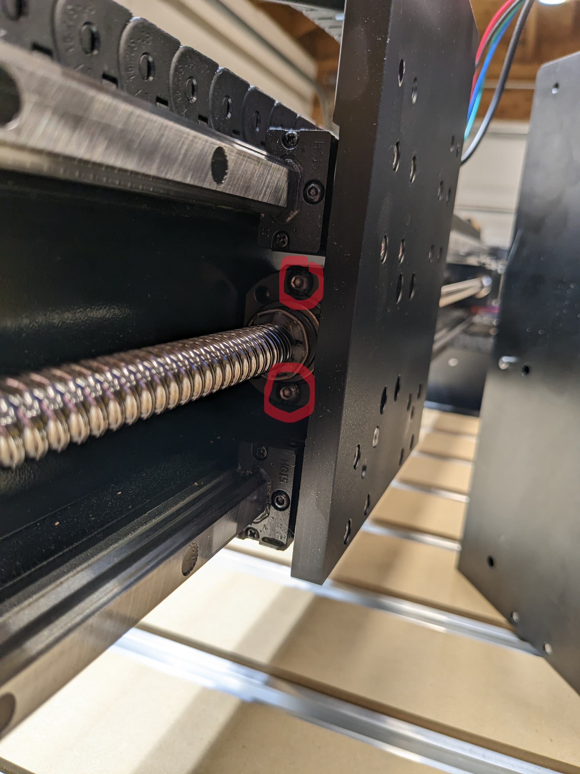
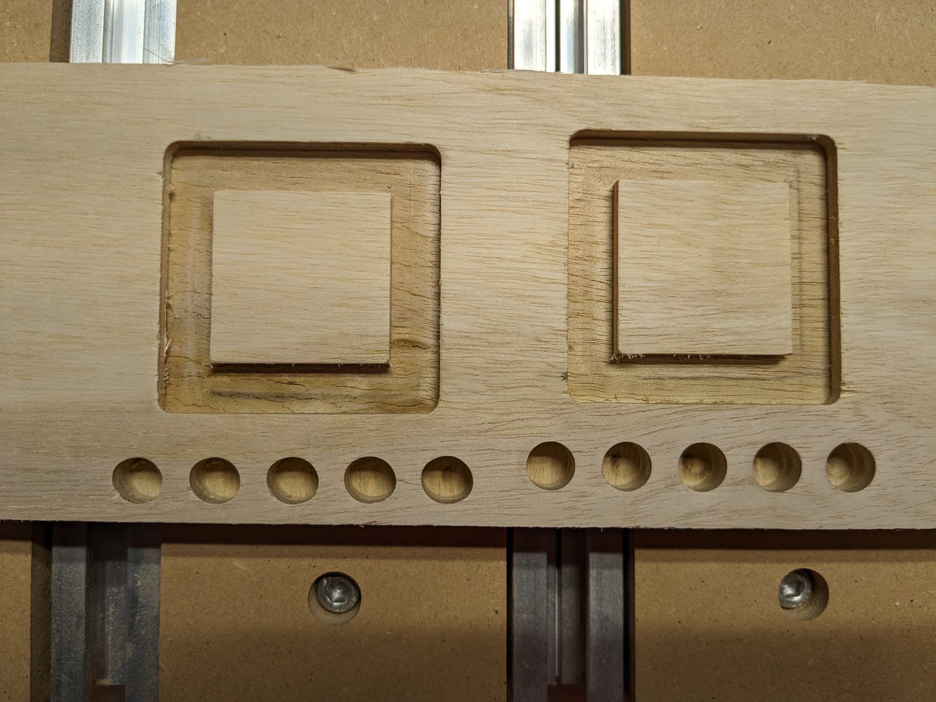
Thank you for the detailed response, very helpful. I found the problem(s), consistent with #2. There was some play where the spindle mount / z axis connects to the x axis, and the two screws in the first image were very loose. I tightened them and it removed a lot of the problems, but I was then getting ovals instead of circles on the next try (see test on the left in the second picture). There was a grub nut on the stepper motor couplers for the left Y axis that wasn’t tightened, and giving some slop. I tightened that and all is well (second picture, test on the right).
I guess this is one potential issue with pre-assembled parts and me being new to the technology. Took me a while to figure out what to check if it wasn’t something I assembled.
Hey live and learn. Will Adams has a machine check list for daily use somewhere on the forum. All machinery periodically needs a good look over and tune up. You would expect a new machine to be all ready but one thing I have learned over my many years of technical service is never take anything for granted.
Your test material looks similar to a piece of plywood I was carving earlier. I bought some cheap plywood at Home Depot that I think is old rubber trees that no longer product and become Chinese furniture and other things. I hate the stuff and will never buy it again but have been using up the scrape on prototypes and utility things.
For the record, this should be: Per the machine operating checklist: Machine operating checklist , the basic points of adjustment for a machine are:
Pulley set screws — verify that these are in-place and secure — be sure to check all axes/pulleys (including Z on machines w/ belt-drive Z-axis, for an HDZ, check both coupler screws).
(for the SO3/4, X- and Y-axes) V wheels / eccentric nuts (per assembly instructions)
(for HDZs, and HDMs, and SO5 Pros) check that couplers between the motor and ball screw are secure, for the SO5 check that the DAC which transfers the rotary motion of the ball screw to linear machine motion is secure on the carriage/gantry
Belt tension (see the relevant step in your instruction manual, Note that the X-axis motor is held in place on standoffs and if those bolts are loose this can cause belt tension issues. Also, belt tension for the Y-axis stepper motors needs to be even/equivalent on each side — a significant difference can cause skipping on one side eventually resulting in lost steps on both. Measuring belt tension, squaring and calibration
Naturally, this assumes that all the wiring is in good condition and all connectors secure per the Machine Operating Checklist. Verify that all wiring is in good condition and all connectors are secure, and that all wiring leading into connectors are properly in place and are secured so that the wiring leading into and away from connectors will not shift.
A good video overview on setup:
Ensure that all screws are in place and secure, esp. on the linear rails on a Pro.