Getting my machine to cut square and keeping it square has been frustrating me for a while. Even when I spent ages squaring up the frame the cutting squareness seemed inconsistent. So I did what any CNC user would do, modded the machine to fix it ![]()
![]()
![]()
Tools required
- A Shapeoko
- Calipers
- A Stick (not calibrated)
- Optional - 3D printer, or you can use the Shapeoko
The Problem(s)
The first problem is that it’s pretty hard to get the frame of the Shapeoko really square, it’s not easy to adjust and the machine doesn’t always want to pull square. There’s only so much trying to measure corner to corner without any clean reference points you can do before you give up and turn stuff into chips instead.
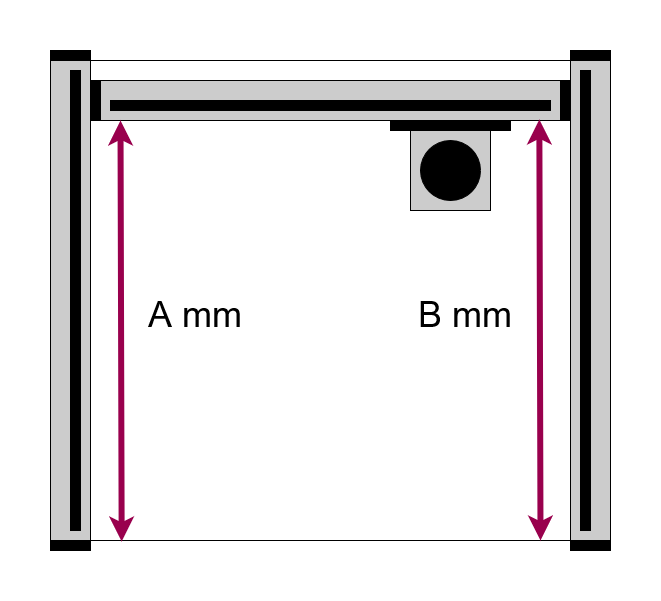
Once you have the frame square the hope is that the machine will start up like this with distance A == B
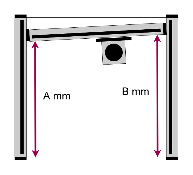
The second is that even if you do get the frame square, that doesn’t mean the X axis will be square to the Y axes. There is enough slack in the V Wheels or linear rail carriages to allow some difference in left and right Y axis position very easily. This will be less on the Pro with the linear rail carriages instead of V wheels, but still not perfect, this is why we need belts and motors on both Y axes.
When you power up your machine the stepper motors power up and go to their nearest whole step increment, from whatever angle your X axis was at when you powered up.
From here the machine homes, but only on one side of the Y axis, it can’t know whether the machine is square or not.
Measuring the gaps between the X axis steel end plates and the ends of the rails is tempting, but not particularly accurate. The frame may not be fully square, trying to get accurate measurements through the nice thick powder coat on the steel is rather tricky and having to do this every startup to check is a PITA.
The Fix
We need to help the machine out a bit, firstly we need to set up so that we can always start the X axis up square to the Y axes, to do this I 3D printed a couple of adjustment stops to go on the rear of the Y rails using the existing Y rail end bolts for fixing.
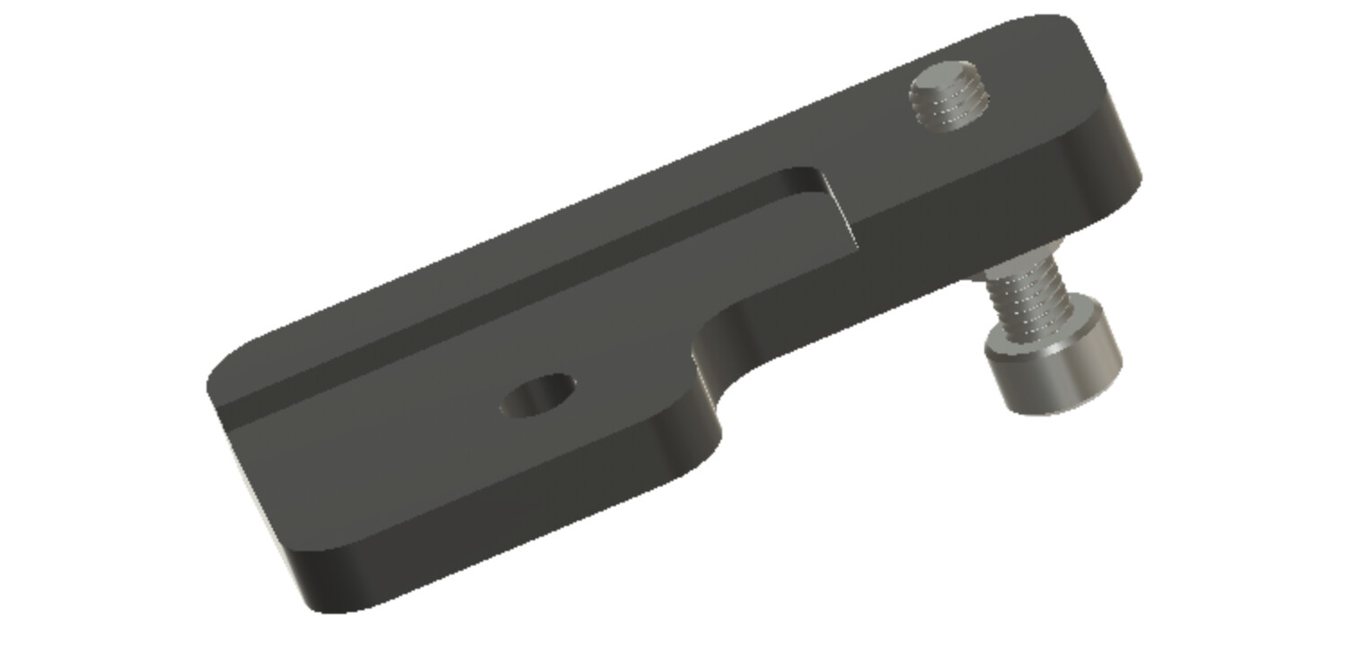
These are just PLA at the moment, the plan was to machine them out of Aluminium later but, that doesn’t seem to be necessary, they’re not subject to any real force and if the machine really crashes into them, they’ll bend instead of the machine.
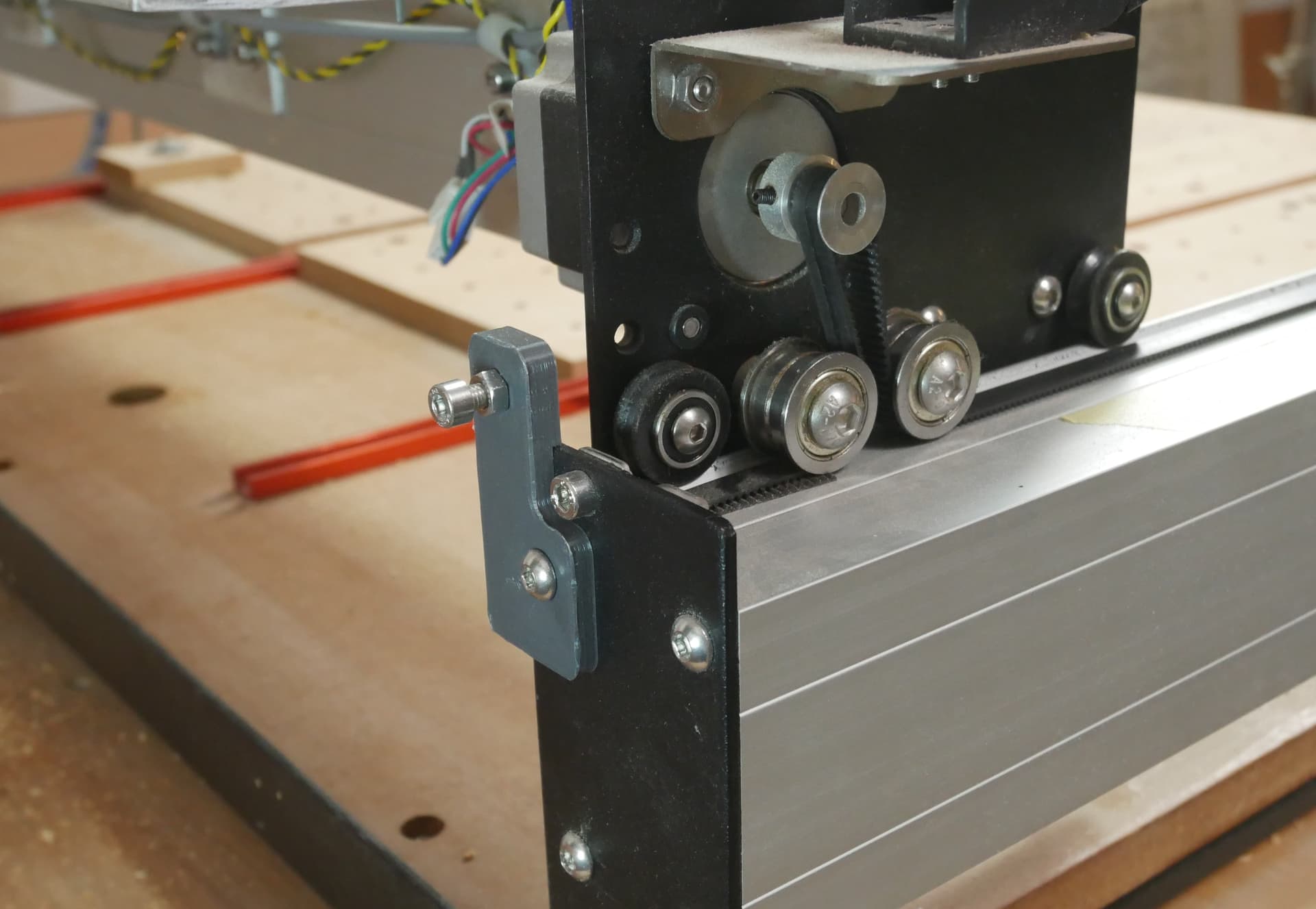
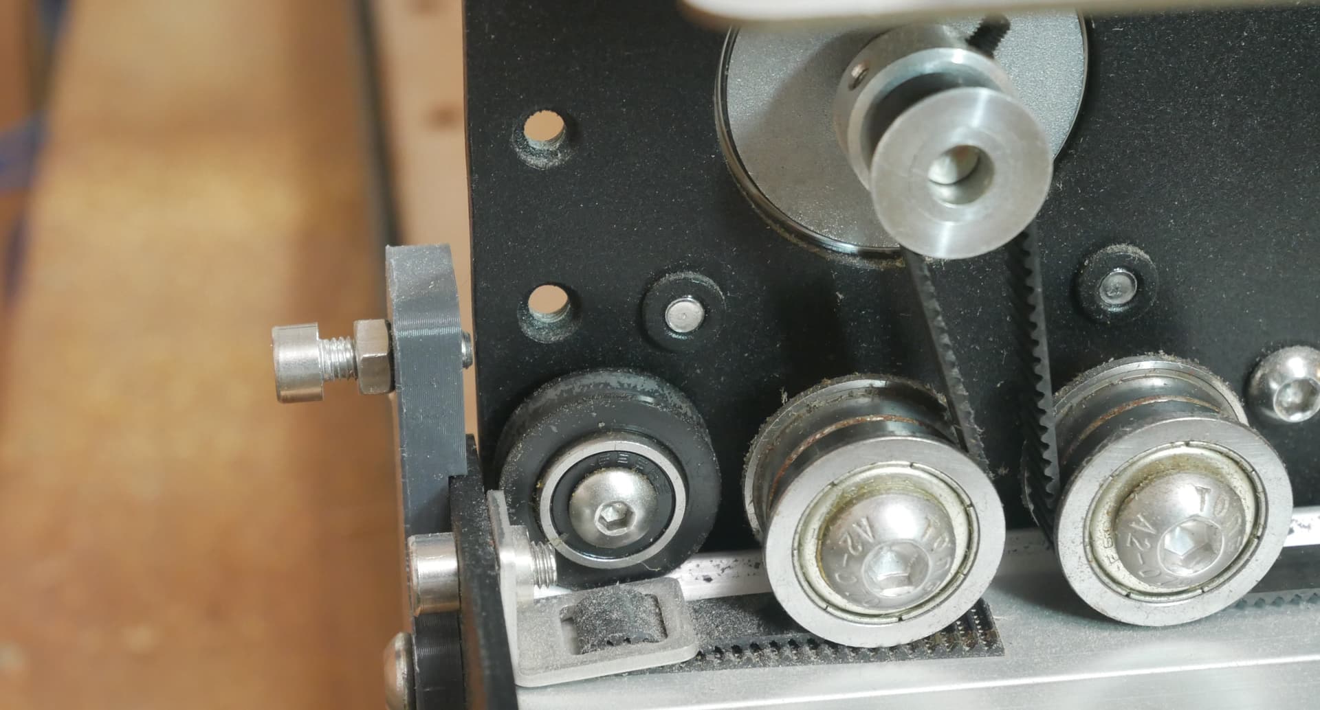
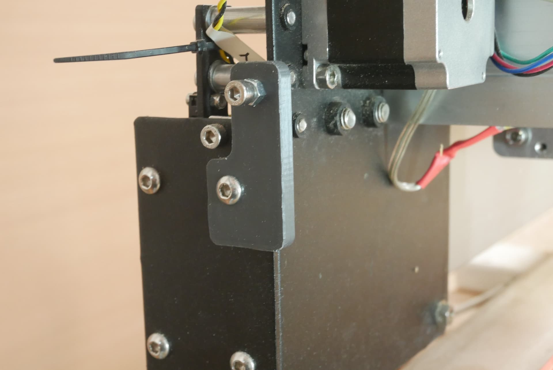
Now we can adjust the bolts so that they hold the Y carriages just before they contact the rear steel plate (be careful of the limit switch if you have the old mechanical ones like I do).
To start the machine up, just use a finger to gently push the X axis back onto the screw stops to align it and then power up.
The machine will start, the steppers will ‘clunk’ to the nearest step, this will be within ± 0.1mm of the starting position on each side. This is the full step size of the motor and represents the hard limit of adjustment precision you can achieve.
The machine is now starting up, finger assisted, with the X axis repeatably at the same angle to the Y axes each time you power it up. First problem solved.
Adjusting to Square
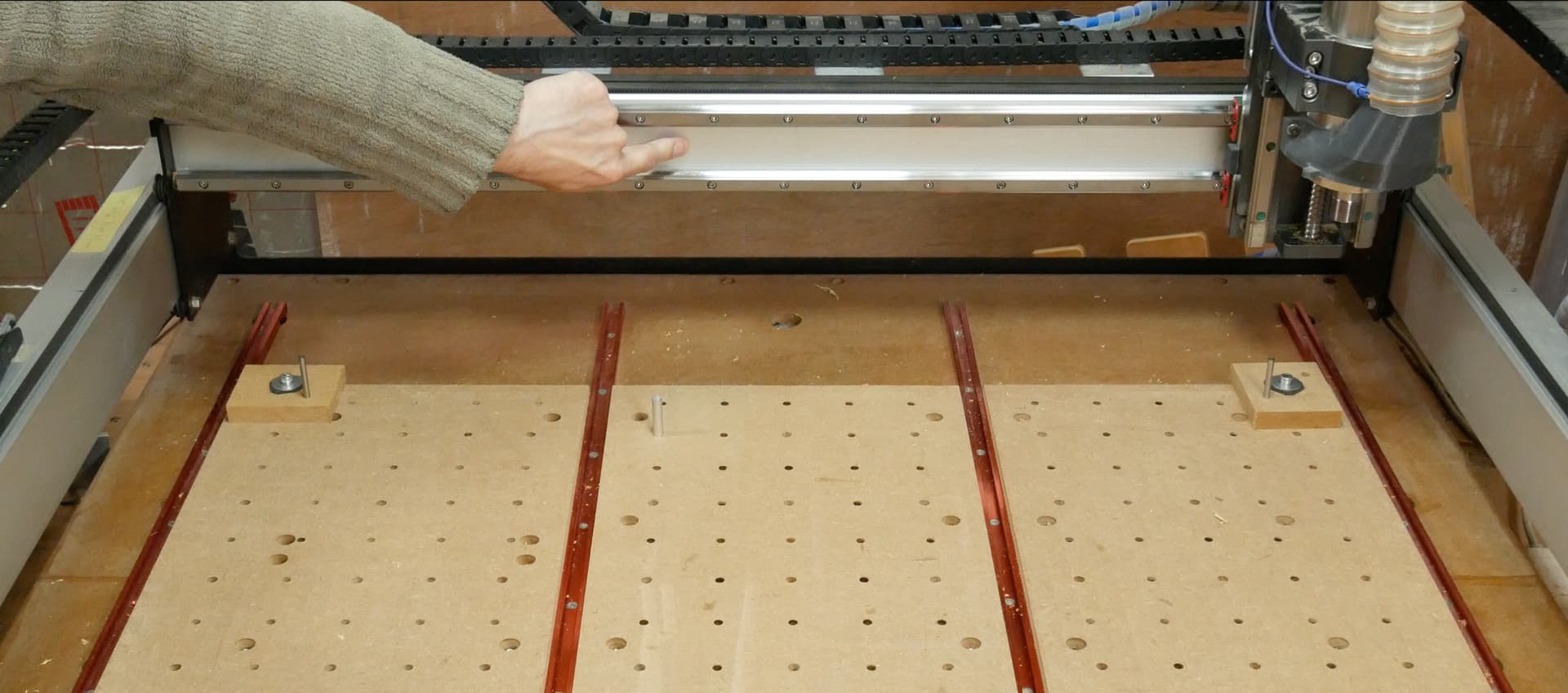
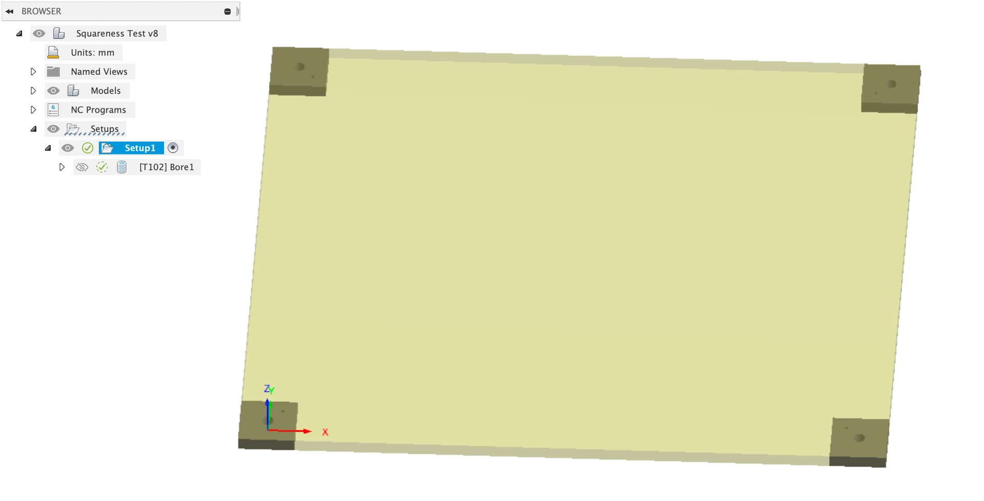
Now that we can start the machine up repeatably it’s worth the time to adjust for square. To do this I bolt 4 chunks of scrap down to my wasteboard in the four corners for maximum separation.
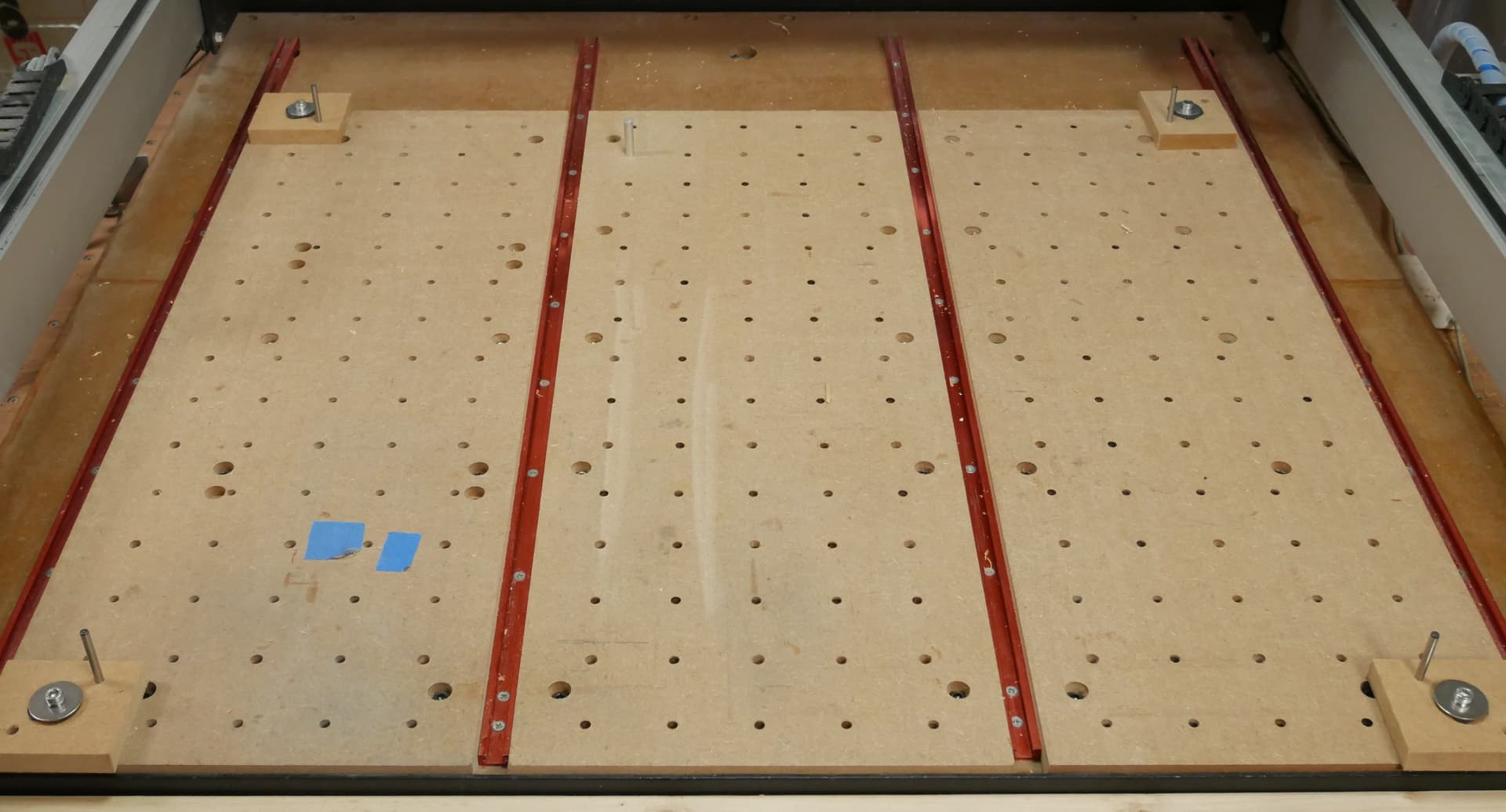
And then run a boring toolpath to cut out holes for 5mm dowel pins in each piece, spaced 700mm x 800mm (for my XXL).
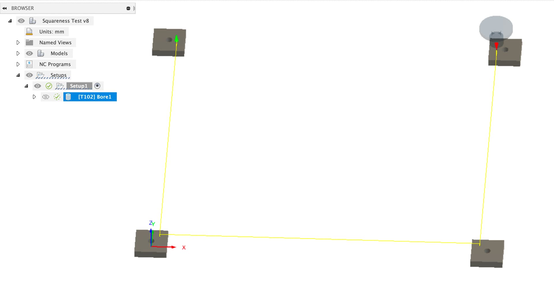
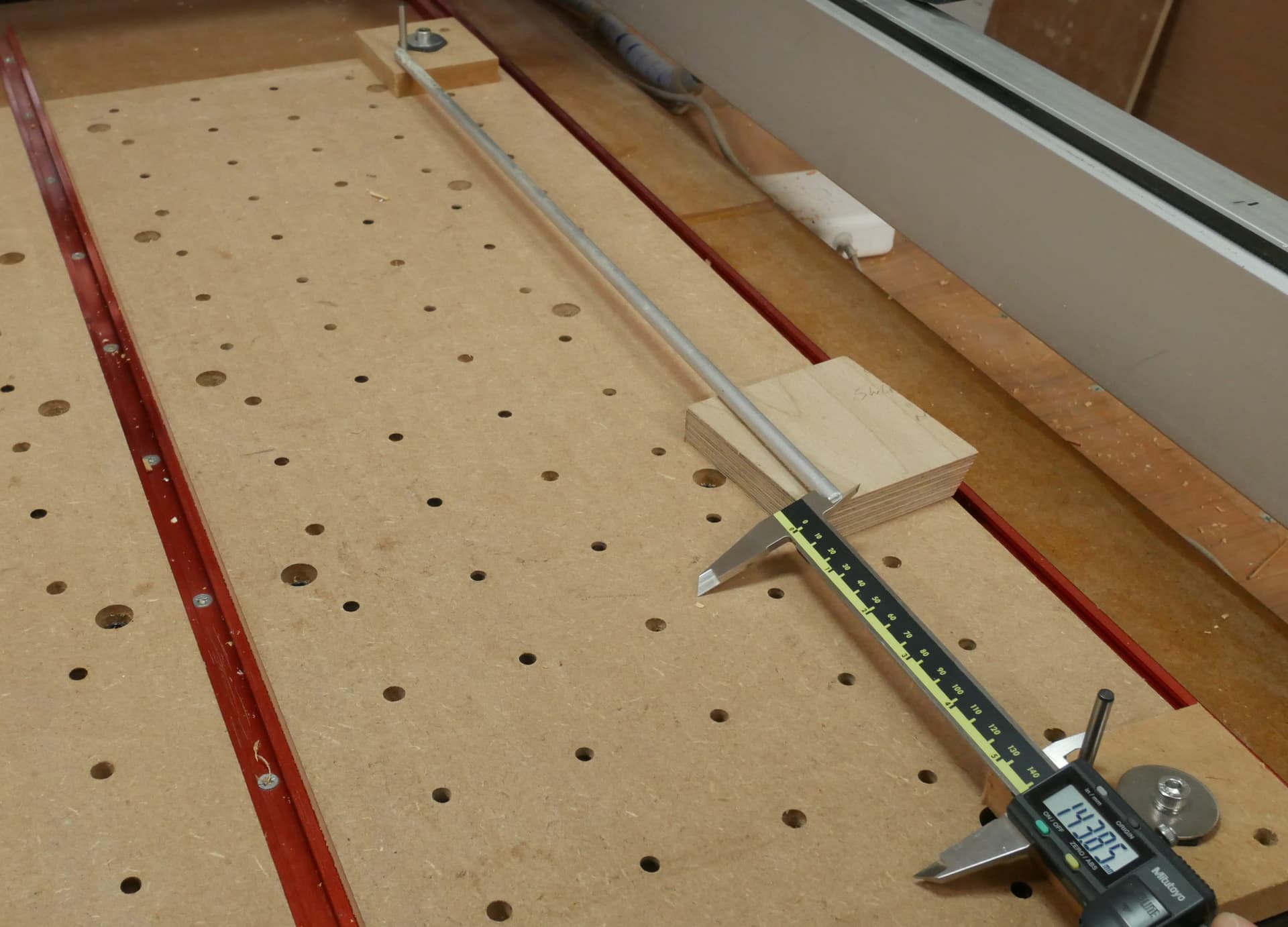
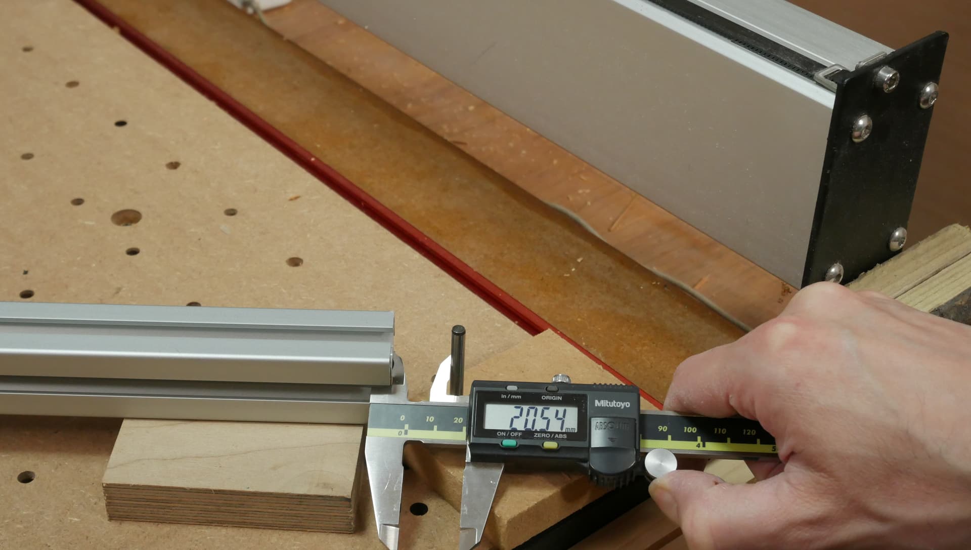
I then stick the dowel pins in the holes and use a stick and calipers to measure
- Measure the two Y axes, check that the distance is the same on both sides, the stick only needs to be long enough to let you use the caliper to measure the gap between stick and dowel pin, we’re comparing the left and right measurements, no precision DIN 866 certified sticks required
If left and right don’t match up well enough then follow the instructions to match up your Y belt tensions from this thread
- Measure the diagonals, now that we know the Y distances are consistent we can compare diagonals to see if they are close enough. Again, the exact length of the stick doesn’t matter, we’re comparing the two diagonals, I have a handy length of Aluminium extrusion
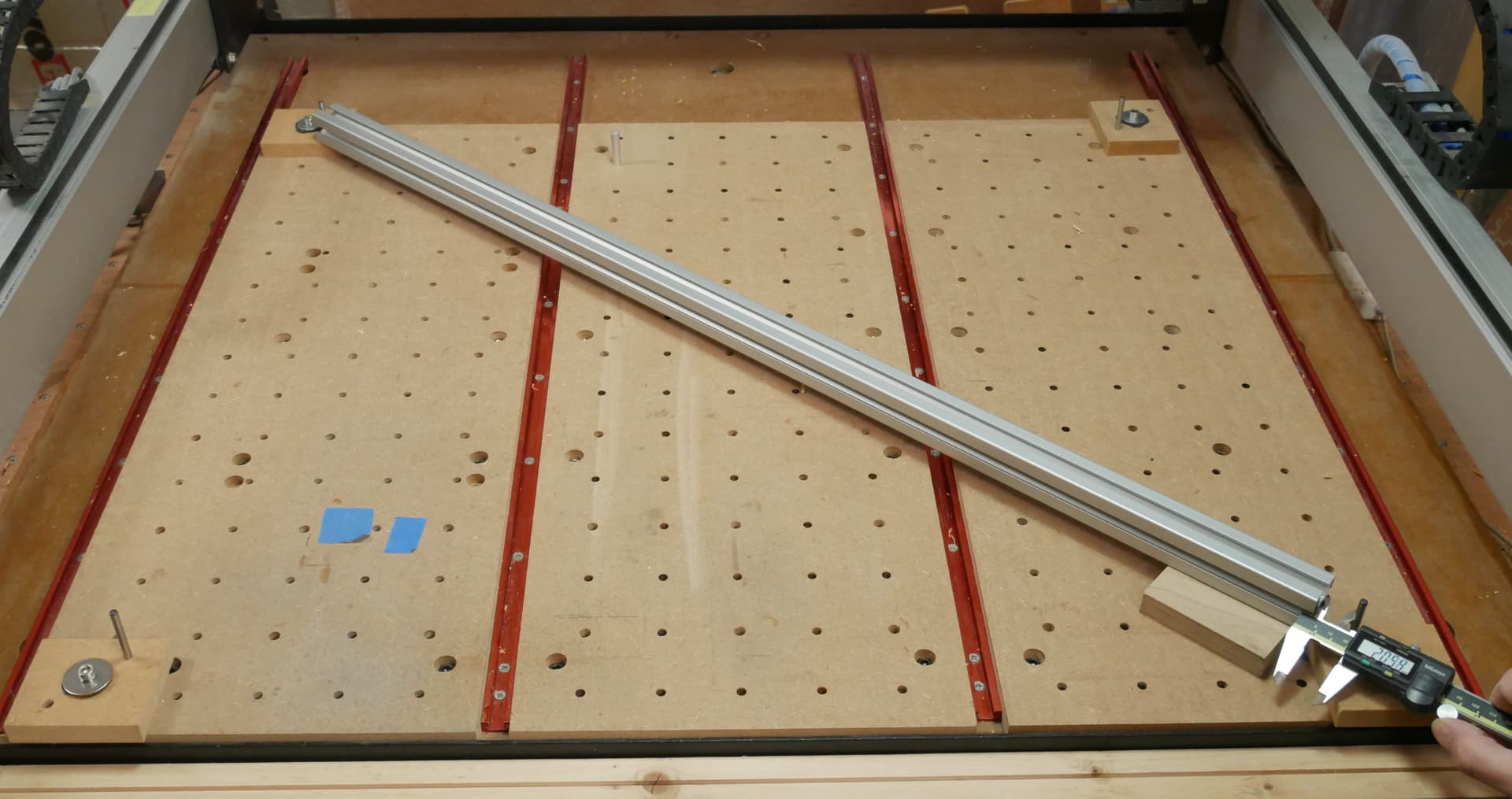
The difference between doing this and trying to measure the frame corner to corner is that this measures what the machine actually cuts, we don’t care if the frame is square (within reason) we care if the machine cuts square.
- If the diagonals are out then go adjust the stop screws at the back of the machine. If your front-left to rear-right diagonal is longer wind the rear right screw in toward the machine, otherwise, the opposite. Turn the machine off, gently push the X axis into the stops, start it up, rotate the blocks, re-run the boring toolpath and check again (remember to pull the dowel pins out before starting the spindle…)
Hope that helps folks, it has certainly made my life easier on jobs where squareness really matters.
Here’s the Fusion file for the stops.
Y Limit Stops v4.f3d.zip (612.6 KB)