Accuracy of ANY kind

I typically get repeatability well under 0.005" constantly. So if I run a program, leave everything be… then run the same program again… it barely touches that material if at all. That is accuracy. What you’re describing sounds like variance in the repositioning of the material.

With you removing and replacing the work piece multiple times, it sounds like workholding and repositioning the material are the culprit, not the machine. Everyone I know that does multiple pours of epoxy on the exact same piece will either do all the cuts and target the pour in individual carves… or leave it in the machine to pour, cure, and do the next area. This is what I have seen regardless of machine. Even ones that cost 10’s of thousands and those glory projects you see on Instagram and YouTube. The picture I’ve attached was done on a Shapeoko (not mine). It was multiple pours on the same part. But they left the material on the machine the whole time in order to avoid variances in clamping and positioning of the material. This is standard practice for multi-pour projects.

Wood is a very malleable material and small differences in clamping pressure will throw things way off. I recommend using a more sturdy fence and clamping system. Like a larger hardwood fence and using the same clamps at the same pressure if you absolutely must carve individual sections, pour individual sections, carve other sections, and pour other sections.

10 Likes

This is an example of someone who carved all the areas at once, did targeterd pours of each area/color.

5 Likes

Thanks for the comments. I could see workpiece holding as part of the problem… but this is off by quite a few millimeters. I’ll run the calibration piece Will suggested and see where that takes me.

@CrookedWoodTex thanks so much for your help.

1 Like

If you want to check the actual machine repeatability, any small project ran again after it cut will tell you. :slight_smile:

1 Like

The reason I asked which tool you have in the spindle is that I see a lot of online videos of people using their end mill when setting X and Y zero. (see the attached video) A completely cylindrical object must be used in order calculate a accurate position. This could be a dowel pin or even a broken end mill inserted upside down in the spindle collet. If you are using an upside down end mill, be sure you are not clamping on the flutes. The size does not matter so long as it fits the collet correctly.

3 Likes

It can be very frustrating initially when you don’t get the accuracy and precision you were expecting, you certainly can get much better outcomes but it takes a bit of learning and understanding each key element of your workflow.

It might be worth posting a step by step, with photos, of how you’re clamping, aligning and zero-ing your workpiece, it’s frequently small things that matter.

I expect to get to < 0.25mm accuracy on any reasonably small part and would expect to be able to remove the workpiece, return it, clamp, indicate and re-machine to this accuracy as well on my SO3 XXL. For workpieces over, say, 500mm I might reduce this expectation to 0.5mm repeatability. Where I’m working in Aluminium I use an edge finder and dial gauge to make sure I really have the setup nailed.

If you’re going to try to do two sided jobs then it is probably worth, once you’ve got the machine giving you repeatable results on single sided, checking out one of the threads on ensuring squareness otherwise this can bite you if your two sided machining needs to line up accurately.

Here’s a job I just ran, which I was able to remove, replace, re-zero and get to < 0.25mm of the previous features.

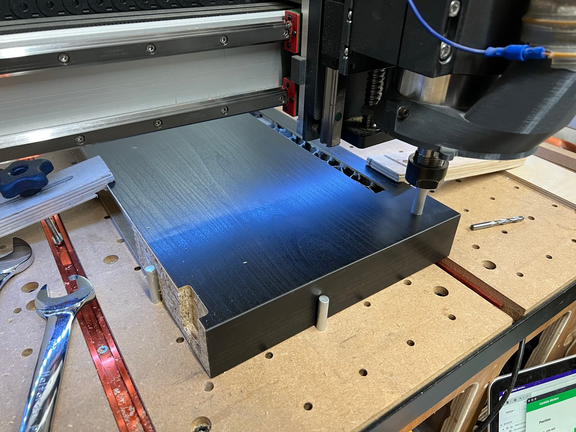
This is the workpiece (an Ikea shelf), it’s clamped on the spoilboard aligned against some 6mm Aluminium rod. Once I had squared up my machine I ran a toolpath to bore 6mm holes in a grid around the machine to let me easily align things.

Hint - align long workpieces along the Y axis, not the X, this way small errors in X axis squareness are minimised.

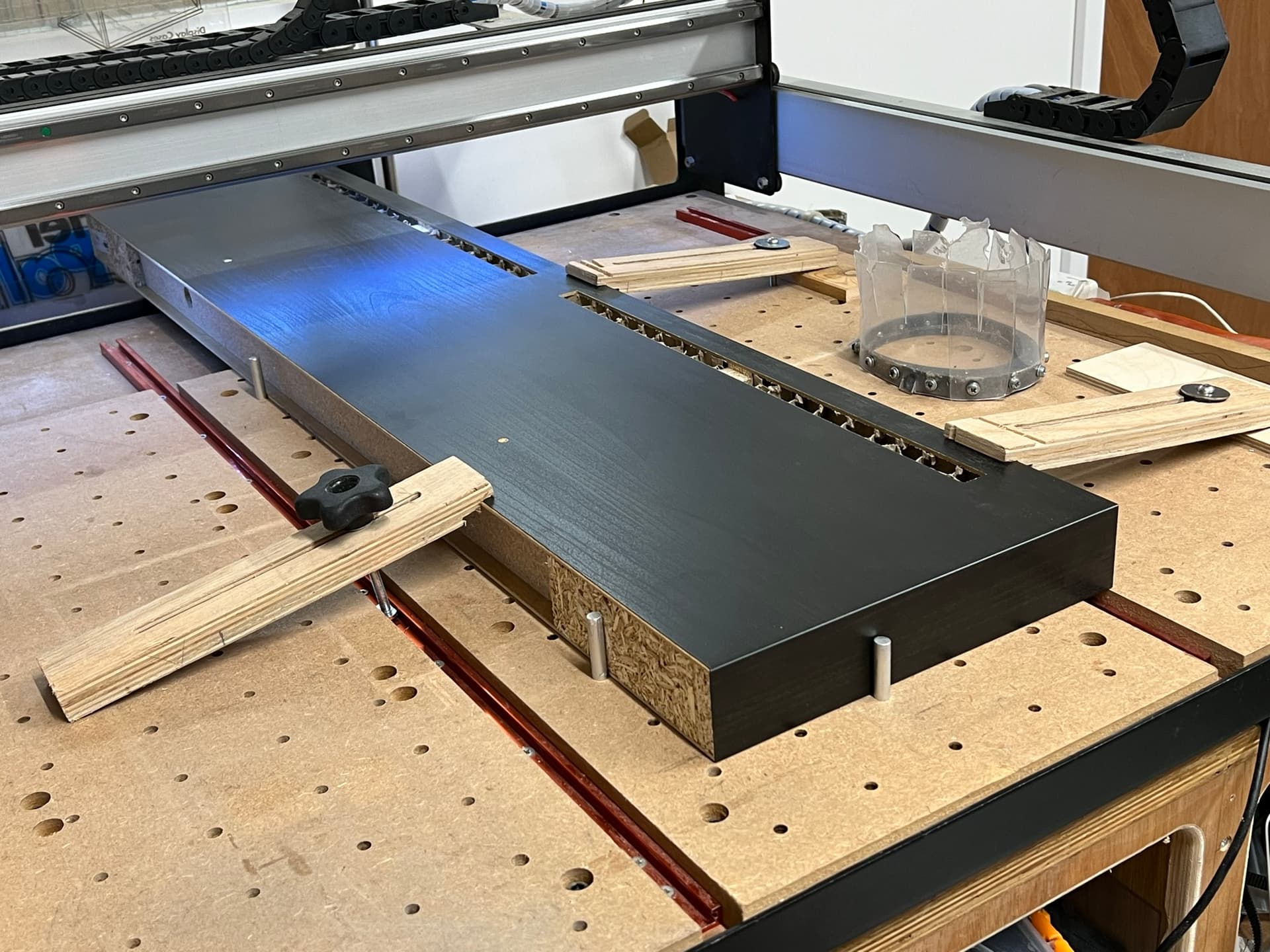
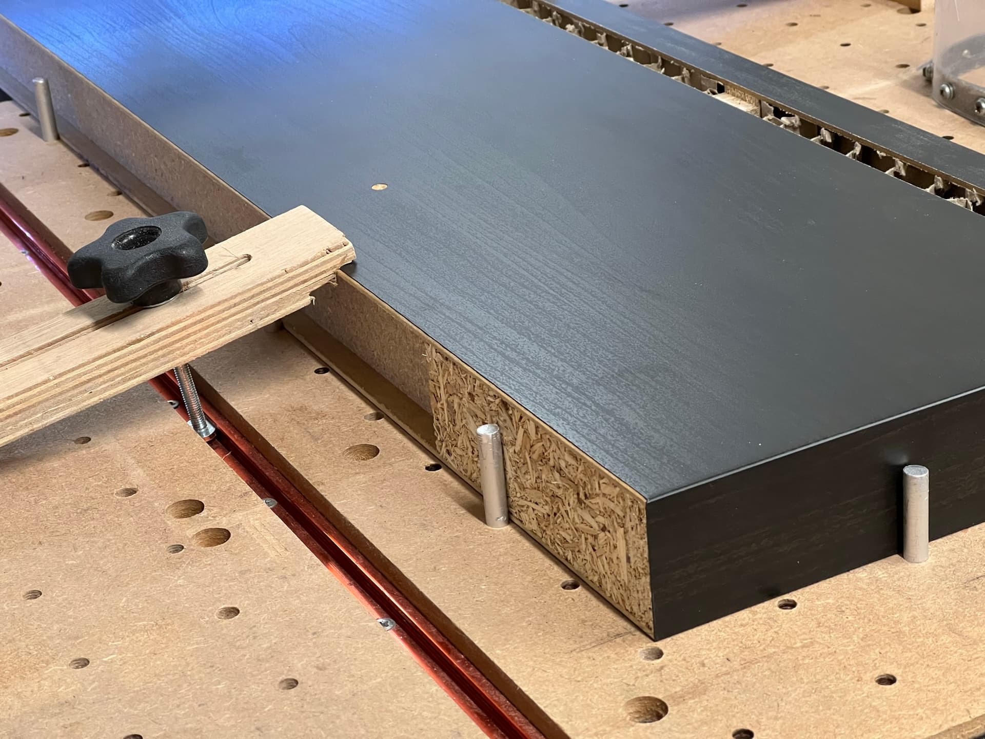
I push the workpiece up against the rods in the Y axis to get it straight, the rod in the X is there as a stop just for repeatability (I had more than one shelf to butcher)

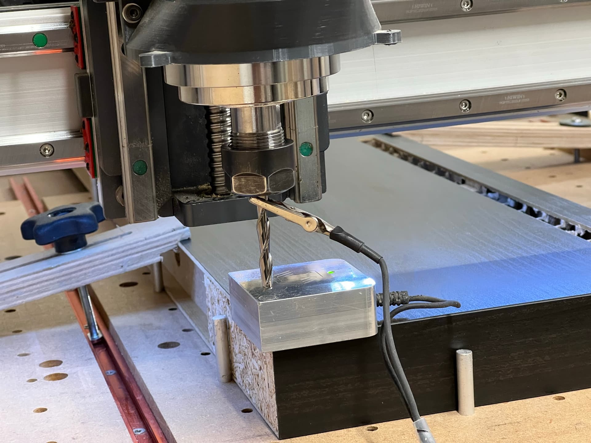
I then used the BitZero with my 1/4" cutter installed, carefully pushed up against two square, clean edges on the workpiece, if you want a repeatable position, ensure you have a feature you can re-zero from partway or after the cuts you plan. I hold the BitZero in place during probing to ensure it doesn’t wobble about.

Probe Corner

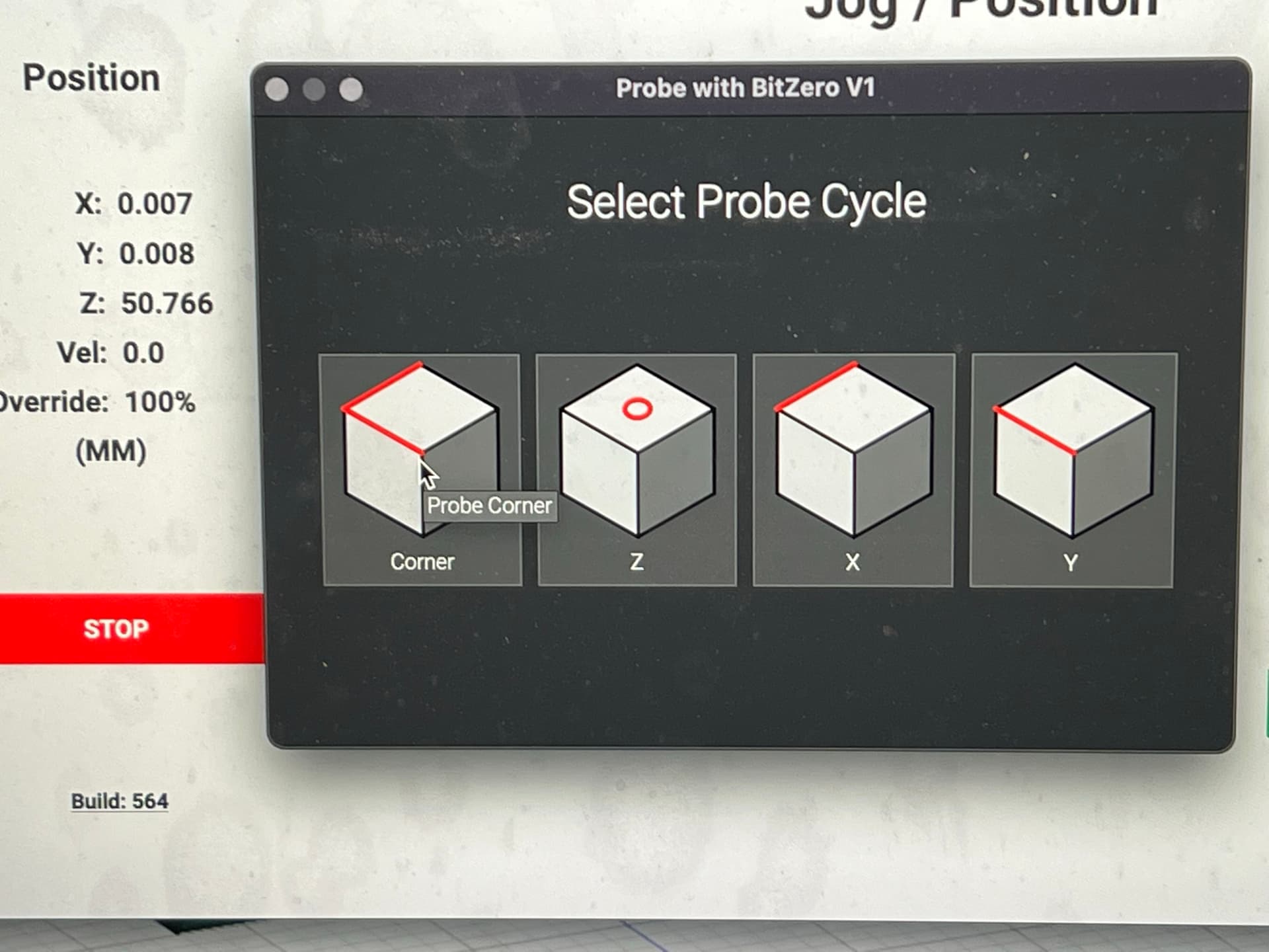
Select the right size bit

I then ran the toolpaths, which included boring a 10mm diameter hole at 226.4mm X and 25.0mm Y in the workpiece.

I removed the workpiece, re clamped it up against the pegs, re-zeroed with the BitZero and sent the machine to X226.4mm Y25.0mm.

I put a peg made from 10mm Aluminium rod into a 10mm collet and jogged down, it’s pretty close, I’d say < 0.25mm error, which, for the BitZero is about as good as it gets, if I need better than this I use an edge finder and ensure the workpiece is straight with a dial gauge.

HTH

Edit - Re Craig’s point - I watch the cutter as the machine probes and make sure that it’s rotated to have the peak of the flute touch the bitzero if not using the Carbide 3 flute high helix where the machine jogs down far enough to ensure that the peak of one flute must be present.

8 Likes

I always use the same 0.25" pin to set my XYZ. Then do a “Load New Tool” to swap to my first tool for the job.

7 Likes

Check your pulley set screws :blush:

2 Likes

@dandangerous, So even with Locklite they were still backing off ?
Interesting

2 posts were split to a new topic: Difficulties learning Carbide Create

Yeah, those small grub screws just couldn’t handle it. My theory is some were pretty short and not making a lot of thread contact in the pulley and there was just enough force that it would rock back and forth breaking free. A longer regular grub screw would work too so it would get more purchase higher up in the pulley threads. But the clearance is not a problem and the socket head screws let you use a larger allen wrench to apply a little more force.

I also applied a dot of the low strength thread lock to the pulley shaft. Carbide actually recommends this in the instructions for the HDZ coupler, apply a small amount to both shafts and screws.

Lots of people will give you warnings about doing this with thread lock and larger screws. But ultimately you’re talking about a couple dollar pulley you can buy any where. If you strip it out, oh well, put a new one on - and really have to try pretty hard to do that.

When I switched to the HDZ, I reused the X motor, but had to pull off the pulley and change the orientation. The purple thread lock held for 2 years, but broke free with nominal force on the new set screws and the motor shaft. Cleaned it up, flipped the pulley, and put a tiny amount of thread lock back on the shaft and set screws again.

Just make sure you’re using the low strength (color varies by brand) meant for this application, not the high strength red!

2 Likes

What if you install a longer set screw/grub screw and ran a jam nut down on it. Could use 2 with a lock washer between.

Couple things on holding down thicker pieces I’m not a fan of 2 sided tape on my shapeoko 4 I run a 3/16 slot on each long edge leaving about 1/8 or so of meat left to clamp down on both sides of my piece if I have a flip program I do the same on the other opposite edge if not I do just one side I even run the grooves on 3/4 inch pieces using my table saw and it works great . One other thing if all possible set your x y z from the center of you piece for better accuracy and when setting it up use a 1/32 bit to pin point center that helps me alot then insert bit you need to use I have the bit setter so it always rereads bit height or you can raise up router insert bit then lower back down to set z

1 Like

Set screws are successfully used in all sorts of applications including heavy duty robotics. It’s probably more important to use high quality grub screws over cheap a shcs. On my 2015 SO3, I don’t think I’ve checked the set screws since I upgraded to an XL (maybe 2017?) if I even did then. As long as one is reasonably tight on the flat, you should be good.
Correctly use the correct tool to tighten them and you shouldn’t have to worry about it.
Also, if you do switch to a socket head screw, use a high quality one. You don’t want that head shearing off or you’ll be grinding off the entire pulley.

7 Likes

There’s a lotta ways to skin the cat. I chose to go simple with a socket head, less parts trying to figure out lock washers and bolts like you mention. Ultimately, I think my machine (and maybe others as well) shipped with some bunk set screws. You can see in my original post some of my grub screws were really short. Not sure if that was the problem or not, but switching to the new screws has solved all the problems and heartache I was having over that with ruined jobs.

While I agree with Neil that changing the hardware here could cause problems, I think everyone way overthinks these screws and miss the problems they cause for some. If you are applying so much force that you snap a socket screw or sheer your threads, well, you might be over-doing it.

I actually had that problem with the original grub screws, I kept re-tightening because they were backing out, trying to crank down to get it to stay, ended up rounding one out with that tiny allen wrench. Luckily I was able to put a dot of super glue on the end of the allen wrench and was able to get it out.

So, YMMV, as with any forum suggested repair, but I feel pretty confident in recommending it if you’re dealing with this - it put an end to it for me.

1 Like

A lot of good tips on here. Thanks. So I guess, to quote someone privately on this thread, “the only person you should be mad at is yourself”

I ran some tests with 4x4 MDF scraps today and carved out some test text. Leaving the board in place and cutting it again, the machine was accurate in the recut. On another test I did the same carve, then reinitialized the machine, and recarved. Same result. I also did a 3rd test with a re-zero. That worked too. So I guess by those tests I must have screwed up my zero-ing and/or placement of the pieces.

I still have some accuracy issues with X distances – if I tell the machine to cut 1" from the left zero point it cuts about 1.05" instead. So I think I just need to do some calibration.

Anyway, if I ever decide to redo this project I’ll try a more rigid fence and the dowels. And definitely use the smooth cylinder endmill for the bitzero-ing

Thanks

8 Likes

Great detective work. :slight_smile: How are you setting your zero by chance?

I put the bitzero v2 on the bottom left corner and put in the 1/8 cylinder. Then use the corner probe feature in CM

1 Like

Seems like a good standard process. Do you hold the BitZero in place?

Yes I hold it down… but I’m not entirely sure I should be doing that. Not sure if the software accounts for that tiny bit of movement.

1 Like