I’m checking runout on my setup. I first used a test indicator on the endmill and got a value (around 0.05mm). Then I tried to compare it with a different method of measuring runout, which is to just cut a slot and measure its actual width, and subtract the endmill diameter.
Using a (supposed) 1/4" (6.35mm) square endmill (#201), I get a slot of…6.30mm. So my endmill is actually smaller than 1/4", it is probably 6.25mm instead of 6.35mm, considering the runout. Is it usual to have a 1.6% difference between the theoretical diameter and the actual diameter ?
My main question is: how do you guys measure the diameter of your endmills, if you ever do ?
I searched and found various ways, but all of them sound complicated to me or require tooling I don’t have (optical thingies).
I acknowledge that what matters in the end is the effective cutting diameter anyway (i.e. actual endmill diameter + runout), but I’m still curious. For a 2-flute endmill, I could just use a caliper or micrometer (being gentle enough to not damage the flutes), but for a 3-flute endmill…?
I have seen few endmills that are “actual” size, and most quality manufacturers have a spec on the permitted variance that follows one or another standard. In practice, there are so many variables at play that it is customary to make test cuts to size the tool. (an example of a manufacturer spec, carefully selected by the method of “first in the search results”: http://www.osgtool.com/Technical.asp?tid=3&id=14 )
On a new tool, the size should be quite close (I expect smaller tools to be within about 0.03mm, never oversize, generally undersize), but reground tools will be smaller (and may be out of tolerance for a new tool), and off brand tools may be pretty much anything. I have unbranded tools from reputable suppliers that, new, are quite far out. For example, 1/8" nominal (6.35mm) that have varied from about 6.25mm and 6.5mm, when carefully measured on the comparator or using a proper fixture. With care, even a good micrometer can be used, but it is easy to chip the cutting edges or the micrometer faces.
EDIT: for a 3 flute endmill, measure on a comparator or between parallel surfaces, such as precision blocks on a surface plate, if you don’t have a vee-anvil micrometer. In a pinch, a GOOD vernier, dial, or digital caliper with large faces can be used, as the faces should be, substantially, parallel. Cheap calipers need not apply for this application.
Thanks for the feedback, it’s good to know that 6.25mm actual for 6.35mm is not completely out of the charts, especially considering I was using an endmill that has seen a lot of cuts already.
Just for fun I checked the price of a decent V-anvil micrometer…and promptly decided I would do without it
the shapeoko wiki has this:
Runout
A quick first pass at determining runout is to simply cut a slot and measure it and compare it to the endmill diameter.
Alternately, cut a 4" square out of the material in question, then measure both the square and the resulting hole — half the difference is the effective cutting width[2], less the endmill diameter is runout.
Considering it’s not obvious to determine the actual endmill diameter, I doubt anyone has ever measured runout precisely using this method. But it does provide the effective cutting diameter, which is what matters.
I guess I’ll just forget about characterizing the endmill diameter alone, and rely on a slot test cut to adjust the effective tool diameter in CAM.
Just note that slotting may not give the most reliable measure for other types of cut, unless the machine is tight and rigid, since any play or vibration will widen the slot further-- slotting is susceptible to this, even when a light finish pass will be on the mark. It is a good indicator, though.
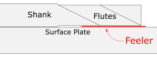
another quick method to check would be a small surface plate and feeler gauge set
carefully lay the endmill down on the shank and find the feeler you hang up on the flutes.
figure out the diameter based on this quick measurement.
shouldn’t set you back much on either plate or gauge and they are handy to have otherwise
Good idea! This will give me an incentive to buy a surface plate and a set of feeler gauges, which as you say will come in handy anyway if I start to do any kind of precision work.
So, if I’m following, the shank is easy to measure, since it’s just a cylinder. The diameter of the flutes will be less than the shank (for this to work). So, using a surface plate as a flat reference plane, you lay the endmill down and then slide feeler gauges between the flutes and the surface plate until you can feel you’re touching the flutes. Then you just subtract twice the feeler gauge thickness from the diameter of the shank, since you’re actually measuring the difference in radius.
the same premise can be used on drill bits also
although be wary of the stamped logo/size of cheaper quality on the shank. this will throw off results and runout for that matter.
Do keep in mind that an endmill is not a drill. They are intended for cutting on their side vs the end. As such, the diameter isn’t generally as critical (hence the discussion about reground endmills), whereas a good drill will hold a well sized hole, an endmill pretty much won’t. For slotting, you’re better off using an endmill smaller than the slot, not on size, and use multiple cuts to get the exact size you want.