I’m using the latest version of Mac MeshCAM Pro/Art.
I’m machining parts for my Nomad 883 Pro dust head. Two of the parts are (identical) brackets. The CAD and STL files were generated with BobCAD-CAM.
I could use the BobCAD-CAM CAM module to machine the part (there is a Nomad 883 Pro “post” available) but I wanted to make sure it could be machined with MeshCAM.
Here is the STL:
Spindle Bracket.stl (495.6 KB)
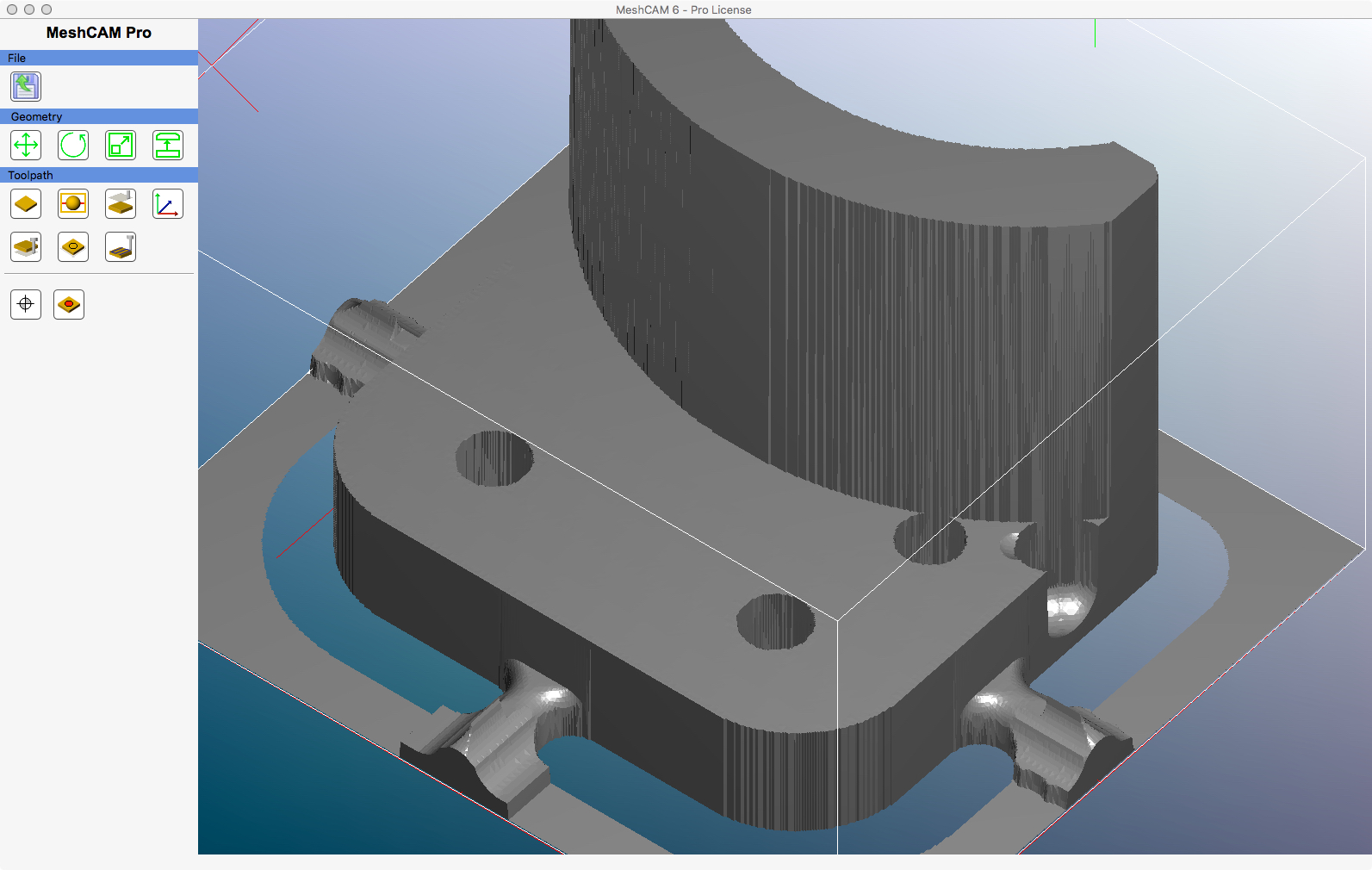
Here is the MeshCAM view of the part:

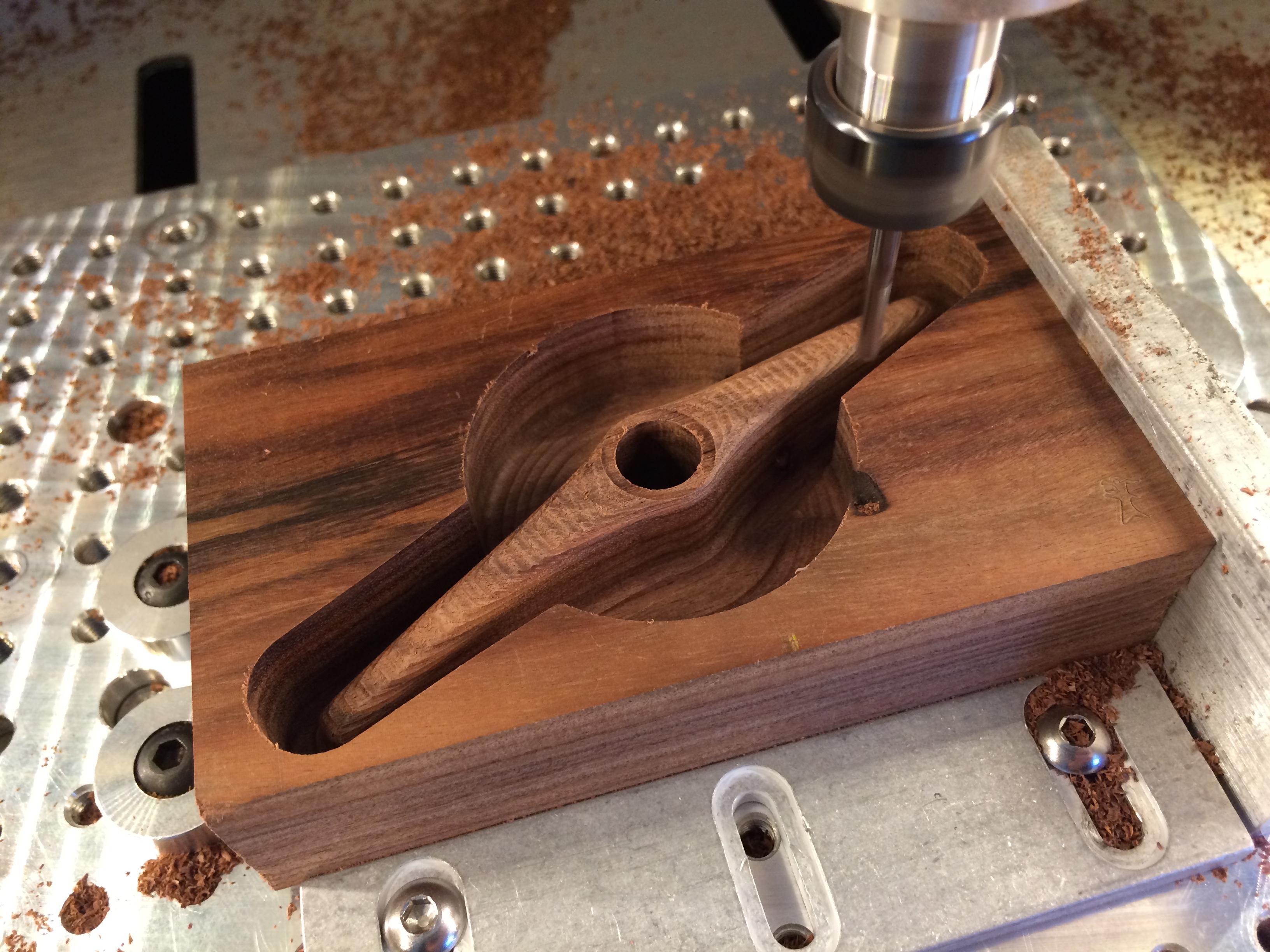
I set up the part, emitted the G Code, and started machining the part. When it finished, I found a gouge.
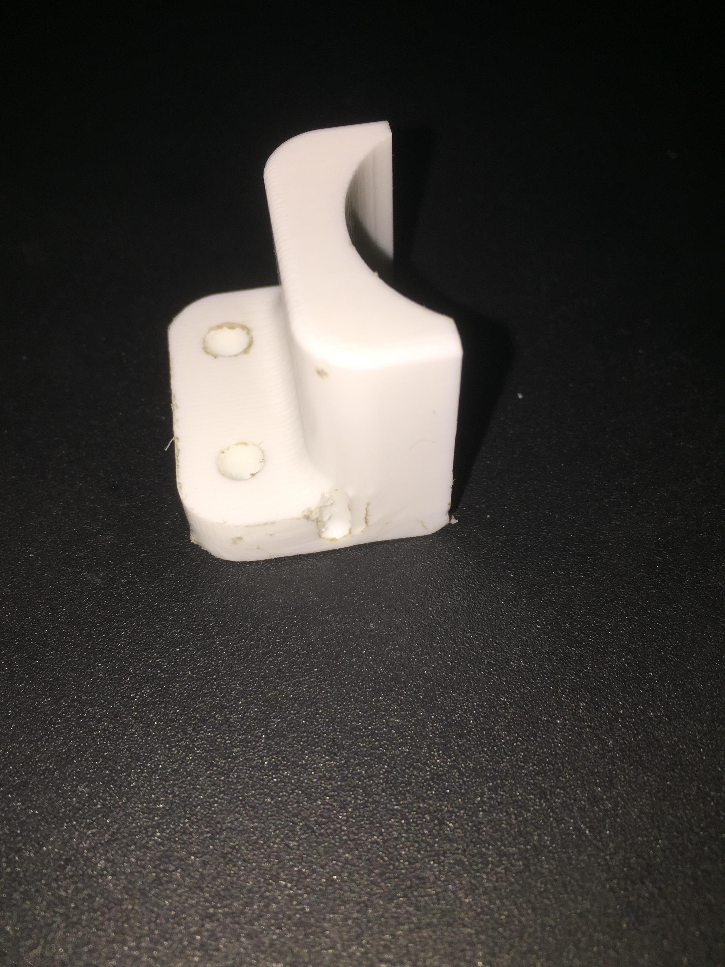
The BobCAD-CAM CAM module machines this part correctly.
I went back to MeshCAM - I use MeshCAM Pro/Art - and ran the simulator. Sure enough, the gouge was there. Because the part is symmetric I never did a full 360; the front was fine and I assumed the back would be the same…
Weird that both sides are identical but a gouge is only on one side…
I ran 'topeScope on the STL and it didn’t find any errors and the part sure looks symmetrical and correct…
I’ve played with MeshCAM for quite some time and cannot find a set of parameters that removes the gouge.
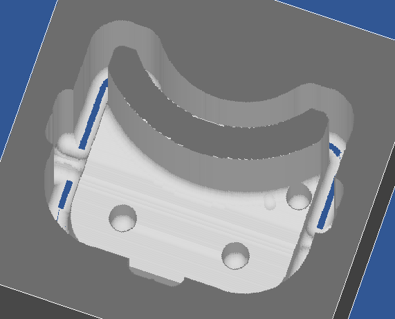
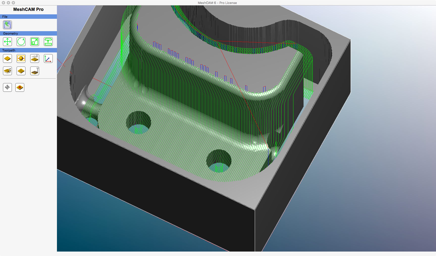
Here is the simulation (the gouge is very obvious):

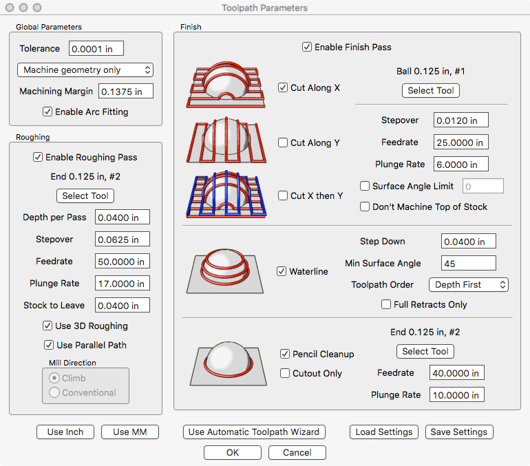
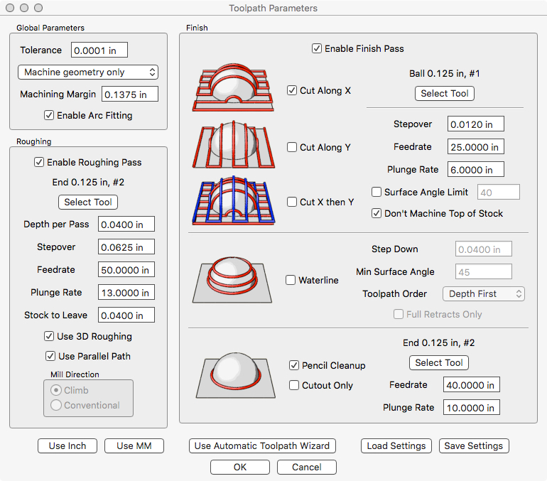
Here are the MeshCAM parameters (everything is at 10K RPM; stock is HDPE), I turned off waterline in this test… it still gouges:
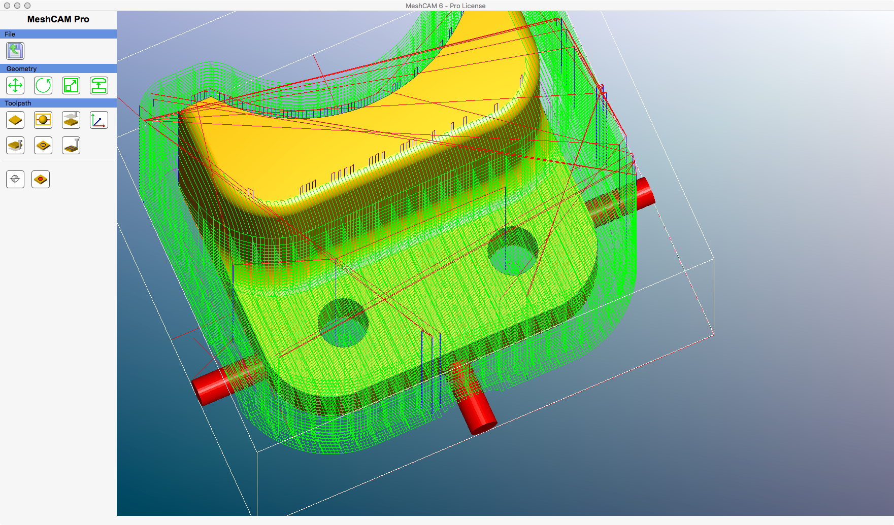
Here are the tool paths:
Here is the simulation showing that the parallel finish is causing the gouge:
Does anyone know why MeshCAM is doing this? Is there a way to prevent this?
mark